vacuubrand VACUU-SELECT Instructions For Use Manual
Hide thumbs
Also See for VACUU-SELECT:
- User manual (108 pages) ,
- Instructions for use manual (96 pages) ,
- Instructions for use manual (50 pages)

Related Manuals for vacuubrand VACUU-SELECT


Summary of Contents for vacuubrand VACUU-SELECT
- Page 1 Technology for Vacuum Systems acuum sensor VACUU·SELECT Sensor ® VACUU·SELECT Sensor with Venting valve ® Instructions for use Original instructions_EN N°: 20901708...
- Page 2 +49 9342 808‑5550 ƒ Service +49 9342 808‑5660 Fax: +49 9342 808‑5555 E-Mail: info@vacuubrand.com Web: www.vacuubrand.com Thank you for purchasing this product from VACUUBRAND GMBH + CO KG . You have chosen a modern and techni- cally high quality product. 20901708_EN_VS-Sensor_V1.2_060420...
-
Page 3: Table Of Contents
Content TABLE OF CONTENT What’s in the box Introduction User information ....... . . 5 1.2 About this document. -
Page 4: What's In The Box
Content Resolving problems 5.1 Fault – Cause – Remedy ......29 5.2 Technical support ....... 29 Cleaning 6.1 Housing surface . -
Page 5: Introduction
They are intended to aid in your understanding of the proper ƒ use of the product. Copyright The content of this manual is protected by copyright. Only copies Copyright © for internal use are allowed, e. g., for professional training. © VACUUBRAND GMBH + CO KG 20901708_EN_VS-Sensor_V1.2_060420... -
Page 6: About This Document
Please ask for replacement in case of an incomplete manual or Contact us ƒ download the manual on our web page: www.vacuubrand.com Contact us regarding any questions about this product, if you ƒ need further information, or to provide us with feedback. -
Page 7: Symbols And Icons
Introduction Additional notes > Information or specific use recommendation, which must be IMPORTANT! observed. > Important information for proper operation. Helpful tips and tricks > Additional information > 1.2.2 1.2.2 Symbols and Symbols and icons icons This manual includes symbols and icons. Safety symbols indicate special danger in handling the product. -
Page 8: Handling Instructions (Action Steps)
Introduction 1.2.3 1.2.3 Handling instructions (action steps) Handling instructions (action steps) Action step (single step) > Do the described step. Presentation convention operating steps 5 Result of action Handling instructions (multiple steps) 1. first step 2. next step 5 Result of action Follow steps in the described order. -
Page 9: Term Definition
Sensor. ® PC 510 select ** like PC 3001 though with valve controlled vacuum control. VACUU·BUS Bus system by VACUUBRAND for commu- ® nication of peripherals with VACUU·BUS ® compatible gauges and controllers. The maximum permissible cable length of one wiring harness is 30 m. -
Page 10: Safety Instructions
Safety instructions Safety instructions Safety instructions The complete information of this chapter must be observed by all persons working with the herein described product. The safety instructions are valid for the complete life cycle of the product. 2.1 Usage Usage Use the product only when it is in proper working condition. -
Page 11: General Safety Instructions
Safety instructions 2.2 General safety instructions General safety instructions 2.2.1 2.2.1 Safety precautions Safety precautions > Use the gauge only if you have understood its function and this Safety precautions manual. > Please note that adhering process media can pose danger to humans and the environment. -
Page 12: Eliminate Sources Of Danger
Safety instructions 2.2.3 2.2.3 Eliminate sources of danger Eliminate sources of danger Sources of error during connection NOTICE NOTICE Mismeasurement due to an obstructed vacuum line. Prevent overpressure > 1060 mbar (795 Torr) inside the > piping system. Condensate can falsify the measurement. No condensate must enter the housing interior via the vacuum hose. -
Page 13: Proper Disposal
>If necessary vent with inert gas. For more and detailed information about ATEX approval visit our website: www.vacuubrand.com/Information‑ATEX 2.3 Proper disposal Proper disposal NOTICE NOTICE Risk of environmental damage due to incorrect disposal of the product. -
Page 14: Product Description
The VACUU·SELECT Sensor complements the VACUU·BUS ® ® VACUU·BUS accessories program of VACUUBRAND. Via VACUU·BUS product supplement ® sensor can be easily integrated into the bus system as client By changing the VACUU·BUS address up to 4 sensors within the ®... -
Page 15: Product View
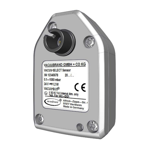
Product description 3.2 Product view Product view Top view, side view VACUU·SELECT Sensor Meaning ® VACUU·BUS plug adapter, removable (option) ® Venting connection, e. g., inert gas (option) Vacuum screw connection, support for ` Hose nozzle DN 6/10 with seal ring and union nut ` Hose PTFE 8/10 directly plugged ` Small flange KF 16, pre‑assembled Socket for VACUU·BUS... -
Page 16: Examples Of Use
Product description 3.3 Examples of use Examples of use Application with CVC 3000 Example Cabinet dryer Meaning Wall power supply, wall power supply plug CVC 3000 (vacuum controller) VACUU·BUS extension cable ® VACUU·SELECT Sensor ® Examples of use: Cabinet dryer Vacuum valve Vacuum hose Diaphragm pump, vacuum pump... - Page 17 Product description Application with DCP 3000 Example Relative pressure measurement (Differential pressure measurement) Meaning Wall power supply, wall power supply plug DCP 3000 (vacuum gauge) VACUU·SELECT Sensor ® ` Sensor measures ambient pressure (Ref._) VACUU·BUS Y adapter ® VACUU·BUS extension cable ®...
- Page 18 Product description Application with VACUU·SELECT ® Example Vacuum concentrator Wall power supply, wall power supply plug Meaning VACUU·SELECT (vacuum controller) with VACUU·SELECT ® ® Sensor – mounted on the rear side Vacuum hose Vacuum connection Examples of use: Vacuum concentrator In-line suction valve Vacuum hose Diaphragm pump, vacuum pump...
-
Page 19: Installation And Connection
Installation and connection Installation and connection Installation and connection 4.1 Transport and goods arrival Transport and goods arrival Products from VACUUBRAND are packaged in a transport‑proof, Transport and packaging recyclable packaging. The original packaging is accurately matched to your product in order for safe transport. -
Page 20: 4.2 Installation Conditions
Installation and connection 4.2 Installation conditions Installation conditions Check installation conditions The device is acclimatized. Installation ƒ conditions Ambient conditions are observed and are within the limitation ƒ of use. Observe limitation of use Limitation of use Limitation of use (US) Ambient temperature 10–45 °C... -
Page 21: Electrical Connection
Installation and connection 4.3 Electrical connection Electrical connection The power supply for the sensor is provided by vacuum controller Electrical connection or vacuum gauge. For power supply use the respective VACUU·BUS connection. ® Via VACUU·BUS interface the measured data will be read out ®... -
Page 22: Connection To Vacuu·select
Installation and connection 4.3.2 4.3.2 Connection to VACUU·SELECT Connection to VACUU·SELECT ® ® This description is intended for the independent retrofitting of the sensor, e. g., replacing a defective sensor. Connect and assemble sensor Power supply via VACUU·BUS direct ® connection Phillips Gr 2... -
Page 23: Connecting Several Sensors
Installation and connection 4.3.3 4.3.3 Connecting several sensors Connecting several sensors Up to 4 sensors and additionally up to 4 reference sensors can be VACUU·BUS ® connected to a controller or gauge via VACUU·BUS principle ® By uniform connectors and Y adapter the bus system can be extended with up to 32 peripherals. -
Page 24: Vacuum Connection
Installation and connection 4.4 Vacuum connection Vacuum connection WARNING Risk of bursting due to overpressure Prevent uncontrolled overpressure, e. g., when > connecting to a closed or blocked tubing system. > Maximum admissable pressure at vacuum sensor: IMPORTANT! 1,5 bar/1126 Torr (absolut). >... -
Page 25: Connection Via Small Flange
Installation and connection 4.4.1 4.4.1 Connection via small flange Connection via small flange Sensor connection via small flange Required connection material: Clamping ring with centering or centering ring for KF DN16 (tool: open‑end wrench size 17). 1. Remove the cap and put the small flange KF DN16 (b) onto the vacuum connection of the sensor (a). -
Page 26: Connection Via Hose Nozzle Or Flexible Hose
Installation and connection 4.4.2 4.4.2 Connection via hose nozzle or flexible hose Connection via hose nozzle or flexible hose IMPORTANT! > Use a vacuum hose that is suitable for the required vacuum range. > Connect hose tubes as short as possible. >... - Page 27 Installation and connection Connect sensor via PTFE hose to vacuum Required connection material: Union nut M14x1, locking ring; op- tionally: PTFE hose , tool: Open‑end wrench SW17. 1. If installed, unscrew the small flange from the sensor (a). (b) (c) 2.
-
Page 28: Venting Connection (Option)
Installation and connection 4.5 Venting connection (Option) Venting connection (Option) DANGER DANGER Risk of explosion by venting with air. Depending on the running process, explosive mixtures can form during venting or other hazardous situations could result! Never vent processes with air which could form an >... -
Page 29: Resolving Problems
Fault – Cause – Remedy Fault – Cause – Remedy For technical help or in case of errors you need additional help for, please contact your local supplier or our Service department. 1 -> Phone: +49 9342 808-5660, Fax: +49 9342 808-5555, service@vacuubrand.com 20901708_EN_VS-Sensor_V1.2_060420... -
Page 30: Cleaning
Cleaning Cleaning Cleaning Clean the sensor to remedy malfunctions that are caused by a polluted sensor. We recommend to clean the sensor prior to ad- justment. IMPORTANT! This chapter does not contain descriptions for the decontam- ination of the product. This chapter describes only simple cleaning and care measures. -
Page 31: Appendix
Appendix Appendix Appendix 7.1 Technical information Technical information Designs Vacuum sensor VACUU·SELECT Sensor ® Vacuum sensor with venting valve VACUU·SELECT Sensor ® 7.1.1 7.1.1 Technical data Technical data Ambient conditions Technical data (US) Working temperature 10–45 °C 50–113 °F Transport and storage tem- ‑10–60 °C 14–140 °F perature... - Page 32 Appendix Vacuum data Technical data VACUU·SELECT Sensor (US) ® Measuring range, 1060–0,1 mbar 795–0.1 Torr absolute Accuracy of < ±1 mbar/hPa/Torr, ±1 digit, with VACUU·SELECT controller (after adjustment, measurement ® constant temperature) Measuring principle Ceramic diaphragm (aluminium oxide, gold‑ coated), capacitive, gas type independent, absolute pressure Temperature coefficient <...
-
Page 33: Wetted Materials
Appendix 7.1.2 7.1.2 Wetted materials Wetted materials Component Wetted materials Wetted materials Vacuum sensor Aluminium oxide ceramics, gold‑coated Measurement chamber Small flange Sealing ring at the sensor chemically resistant fluoroelas- tomer O‑Ring inside small flange Hose nozzle Venting valve seal FFPM Blind plug venting valve Epoxy resin adhesive... -
Page 34: Ordering Information
Purchase original accessories and spare parts from your spe- International cialized distributor or through international sales offices of sales offices and specialized trade VACUUBRAND GMBH + CO KG. Information about the complete product range are available > in the current product catalog. -
Page 35: Service
Appendix 7.3 Service Service Take advantage of the comprehensive service range of Service offer and VACUUBRAND GMBH + CO KG. service range Service in detail product guidance and practical solutions, ƒ fast delivery of spare parts and accessories, ƒ professional maintenance, ƒ... -
Page 36: Index
Appendix 7.4 Index Index Index Abbreviations ....8 Personnel (staff) ....11 Accessories . -
Page 37: Ec Declaration Of Conformity
EC Declaration of Conformity Déclaration CE de conformité Hersteller / Manufacturer / Fabricant: VACUUBRAND GMBH + CO KG · Alfred‑Zippe‑Str. 4 · 97877 Wertheim · Germany Hiermit erklärt der Hersteller, dass das Gerät konform ist mit den Bestimmungen der Richtlinien:... -
Page 38: Declaration Of Conformity 符合性声明 - China Rohs 2
– China RoHS 2 DECLARATION OF CONFORMITY – China RoHS 2 VACUUBRAND GMBH + CO KG has made reasonable efforts to ensure that hazardous materials and substances may not be used in its products. In order to determine the concentration of hazardous substances in all homogeneous materials of the subassemblies, a “Product Conformity Assessment”... - Page 39 (Pb), mercury (Hg), cadmium (Cd), hexavalent chromium (Cr+VI), polybrominated biphenyls (PBB), and polybrominated diphenyl ethers (PBDE). Products manufactured by VACUUBRAND may enter into further devices (e.g., rotary evaporator) or can be used together with other appliances (e.g., usage as booster pumps).
- Page 40 Technology for Vacuum Systems Manufacturer: VACUUBRAND GMBH + CO KG Alfred‑Zippe‑Str. 4 97877 Wertheim GERMANY Phone: ƒ Head office +49 9342 808‑0 ƒ Sales +49 9342 808‑5550 ƒ Service +49 9342 808‑5660 Fax: +49 9342 808‑5555 E-Mail: info@vacuubrand.com Web: www.vacuubrand.com...
Need help?
Do you have a question about the VACUU-SELECT and is the answer not in the manual?
Questions and answers