Table of Contents
Advertisement
page 1 of 36
Technology for Vacuum Systems
Instructions for use
II
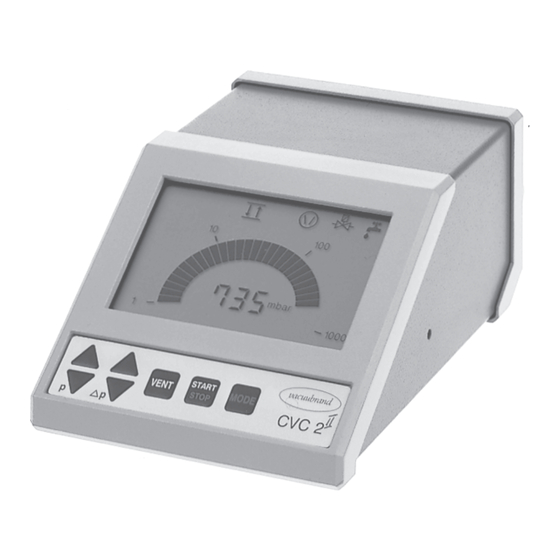
CVC 2
Vacuum controller
Documents are only to be used and distributed completely and unchanged. It is strictly the users´ responsibility to check
carefully the validity of this document with respect to his product. manual-no.: 99 90 20 / 01/12/2004
Advertisement
Table of Contents

Related Manuals for vacuubrand CVC 2


Summary of Contents for vacuubrand CVC 2
- Page 1 1 of 36 Technology for Vacuum Systems Instructions for use CVC 2 Vacuum controller Documents are only to be used and distributed completely and unchanged. It is strictly the users´ responsibility to check carefully the validity of this document with respect to his product. manual-no.: 99 90 20 / 01/12/2004...
- Page 2 2 of 36 Dear customer, Your VACUUBRAND controller should support you for a long time without trouble and with maximal power. Thanks to our long practical experience we have much information how you could ensure powerful application and personal safety. Please read these instructions for use before the initial operation of your controller.
-
Page 3: Table Of Contents
page 3 of 36 Contents Safety information! ....................4 Technical data......................6 Description ........................7 General view basic setups ..................9 How to work with the controller ................10 General view basic setup ”Standard” ..............11 Basic setup Standard ..................... 12 Vacuum management with VMS Module A ............16 Basic setup Management or Management Plus ...........20 General view basic setup VACUU•LAN ..............22 Basic setup VACUU•LAN ..................23... -
Page 4: Safety Information
☞ Read and obey this manual before installing or operating the equipment. Use the equipment for the intended use only (for measurement and control of vacuum). Operate the controller only in combination with VACUUBRAND genuine accessories (e. g. isolation valve, vacuum management module VMS A). Make sure that the individual components are only connected, combined and operated according to their design and as indicated in the instructions for use. - Page 5 page 5 of 36 Adopt suitable measures to prevent dangers arising from dangerous or explosive gases and dangers arising from the formation of explosive fluids or explosive or flammable mixtures and ensure that the materials of the wetted parts are compatible, see section “Technical data”.
-
Page 6: Technical Data
page 6 of 36 Technical data < < t f i < ° 0 ° 0 ° 0 ° 0 ° 0 Ø Ø , " i - l c i l We reserve the right for technical modification without prior note! Documents are only to be used and distributed completely and unchanged. -
Page 7: Description
page 7 of 36 Description Operating the controller is possible in four different basic setups, see ”Changing the basic setup”. The status of the controller respectively of the connected accessories is displayed by corresponding symbols on the LCD. After switching on the controller, the version of the software is displayed, then the preselected basic setup. - Page 8 - setting of set point p - switching in programs START VENT MODE STOP CVC 2 ∆ ∆ ∆ ∆ ∆ setting of hysteresis ∆p or operating the built - start or stop of process control in air admittance time t for switch-off...
-
Page 9: General View Basic Setups
9 of 36 General view basic setups CVC 2 setting pressure unit (mbar / Torr / hPa) setting basic setup basic setup ”Standard” (factory-set) controller switches solenoid operated isolation valve (indispensable) cooling water valve (optional) basic setup ”Management”* controller switches... -
Page 10: How To Work With The Controller
page 10 of 36 How to work with the controller How to change the pressure units Press key p▲ or p▼ while switching on. ☞ The pressure units are displayed, the pressure unit as from mbar last operation is flashing. Torr ➨... -
Page 11: General View Basic Setup "Standard
page 11 of 36 General view basic setup ”Standard” setting the basic setup basic setup Standard configurate switching cooling cooling water valve water valve? setting the operation mode continuous two-point control pumping pumping semiautomatic manual setting: down to ulti- determination of set point (boiling point) mate vacuum the boiling point... -
Page 12: Basic Setup Standard
page 12 of 36 Basic setup Standard After switching on The process control is inactive, i. e. controller is ready for vacuum control, but control operation has not been activated. ☞ The controller is in operation mode two-point control, the actual pressure is displayed. - Page 13 page 13 of 36 Continuous pumping Pumping down until the ultimate vacuum of the pump is attained (e. g. pump down to dry the system from volatile liq- uids): If the controller is in mode two-point control: MODE ➨ Press key MODE to change to continuous pumping. ☞...
- Page 14 page 14 of 36 ➨ Start: Press key START/STOP. ☞ Arrow down and valve and/or pump symbol are flashing: Su- pervise process permanently. START STOP ➨ When sufficient evaporation appears: Press key MODE. ☞ Continuous pumping is stopped. The actual pressure p is stored as new set point.
- Page 15 page 15 of 36 Example basic setup Standard: PC 510 connected to a rotary evaporator vacuum connection coolant coolant electrical circuit Documents are only to be used and distributed completely and unchanged. It is strictly the users´ responsibility to check carefully the validity of this document with respect to his product.
-
Page 16: Vacuum Management With Vms Module A
The vacuum controller CVC 2 offers four basic setups depending on the components of the VACUUBRAND chemistry vacuum system which are con- nected to the system. the specific user and/or process requirements. - Page 17 page 17 of 36 c t i c t i c t i L • ® c t i c t i c t i l l o e l l L • ® l l o Documents are only to be used and distributed completely and unchanged. It is strictly the users´ responsibility to check carefully the validity of this document with respect to his product.
- Page 18 ☞ ☞ ☞ ☞ ☞ An isolation valve is indispensable. ☞ Dispenses the cooling water according to the requirements (cooling water valve 24 V= at the CVC 2 Management ☞ ☞ ☞ ☞ ☞ A VMS Module A is indispensable.
- Page 19 page 19 of 36 After setting the basic setup: ☞ The symbol of the cooling water valve is displayed and ”yes” or ”no”. ➨ Press key p▲ or p▼ to activate (”yes”) or to inactivate (”no”) the cooling water valve and press key START/STOP to con- firm.
-
Page 20: Basic Setup Management Or Management Plus
page 20 of 36 Basic setup Management or Management Plus Starting and stopping the process control, venting the system and the operation modes two-point control and continuous pumping are described in section ”basic setup Standard”. If the cooling water valve is preselected, the cooling water valve opens immediately after starting the process control (the cooling water valve 24 V= at the controller is operated parallel (synchronous) to the cooling water valve at the VMS Module A), the according symbol is displayed. - Page 21 page 21 of 36 ® Example basic setup Management: MZ 2C + AK + EK, VACUU•LAN components with isolation valves vacuum connection coolant coolant electrical circuit Example basic setup Management: MZ 2C + AK + EK, without isolation valve vacuum connection coolant coolant electrical circuit...
-
Page 22: General View Basic Setup Vacuu•Lan
page 22 of 36 General view basic setup VACUU•LAN setting the basic setup basic setup VACUU•LAN connect cooling switching cooling water valve water valve? setting process parameters ➨ pressure value (condition for automatic shut down) ➨ upper set point (condition for restart) ➨... -
Page 23: Basic Setup Vacuu•Lan
page 23 of 36 Basic setup VACUU•LAN After switching on The process control is inactive, i. e. the controller is ready for vacuum control, but control operation has not been activated. In basic setup VACUU•LAN it is not possible to activate the two-point control. - Page 24 page 24 of 36 Setting the process parameter Setting the time for automatic shut down: ➨ Press key ∆p▲ or ∆p▼. ☞ ”Set” and the clock symbol and the time for automatic shut down are displayed for approx. 1 s (factory-set 15 min). ☞...
- Page 25 page 25 of 36 ® Example basic setup VACUU•LAN: PC 510, VACUU•LAN components with isolation valve, ball valve or flow control diaphragm vacuum connection coolant coolant electrical circuit Documents are only to be used and distributed completely and unchanged. It is strictly the users´ responsibility to check carefully the validity of this document with respect to his product.
-
Page 26: How To Determine The Best Distillation Conditions
page 26 of 36 How to determine the best distillation conditions Measure the temperature of the available coolant. ☞ In most cases the coolant temperature is given (e. g. tap water, in house cooling water circuit). For maximum solvent recovery, carefully choose the boiling point of the product (by choosing the vacuum level) and the bath temperature accordingly. -
Page 27: Installation And Accessories
Components the VACUUBRAND chemistry vacuum system consists e. g. of the following components: Vacuum generation Chemistry diaphragm pump MD 4C (230 V, 50/60 Hz) 3,0 m /h, 2 mbar ............ - Page 28 Cooling water valve 230 V~, 50-60 Hz ..... 67 60 10 (for use with the VMS) Y-socket-plug connector ......... 67 60 15 (to connect several components to the bush of the CVC 2 , e. g. for simultaneous operation of isolation valve and VMS)
-
Page 29: Troubleshooting
page 29 of 36 Troubleshooting d l i v i t . r i l i t v i t . r i l l a c t i , f f n i l f i r i l e >... - Page 30 page 30 of 36 c t i , f f i t c . r i y l t . y l o l l n i l i t c l l o . r i c t i Instructions for repair with directions for repair and spare parts list are available on request.
-
Page 31: Readjustment
page 31 of 36 Readjustment The device was adjusted using factory standards, which are traceable through regular calibration in an accredited laboratory (German Calibration service) to the national stand- ard. Depending on the process and/or accuracy requirements, check the adjustment and readjust if necessary. -
Page 32: Calibration In The Factory
Calibration in the factory Control of measuring equipment The VACUUBRAND DKD calibration laboratory is accredited by the Physikalisch-Technische Bundesanstalt (PTB; German national institute for science and technology and the highest technical authority of the Federal Republic of Germany for the field of meteorology and certain sectors of safety engineering) for the... -
Page 33: Notes On Return To The Factory
page 33 of 36 Notes on return to the factory Repair - return - DKD calibration Safety and health of our staff, laws and regulations regarding the handling of danger- ous goods, occupational health and safety regulations and regulations regarding safe disposal of waste require that for all pumps and other products the “Health and safety clearance form“... -
Page 34: Health And Safety Clearance Form
D-97877 Wertheim - Alfred-Zippe-Str. 4 Tel. (++49)9342 / 808-0 - Fax (++49)9342 / 59880 © 2003 VACUUBRAND GMBH + CO KG Printed in Germany Documents are only to be used and distributed completely and unchanged. It is strictly the users´ responsibility to check... - Page 35 ......Ort, Datum / place, date / lieu, date (Dr. R. Lachenmann) Geschäftsführer / Managing director / Gérant VACUUBRAND GMBH + CO KG D-97866 Wertheim -Vakuumtechnik im System- Postfach / P. O. Box / B. P. 1664...
- Page 36 Tel. (++49)9342 / 808-0 - Fax (++49)9342 / 59880 © 2004 VACUUBRAND GMBH + CO KG Printed in Germany 99 90 20 Documents are only to be used and distributed completely and unchanged. It is strictly the users´ responsibility to check...
Need help?
Do you have a question about the CVC 2 and is the answer not in the manual?
Questions and answers