vacuubrand CVC 3000 Instructions For Use Manual
Vacuum controller
Hide thumbs
Also See for CVC 3000:
- Instructions for use manual (124 pages) ,
- Instructions for assembly (12 pages) ,
- Instructions for use manual (80 pages)
Table of Contents
Advertisement
Quick Links
page 1 of 42
Technology for Vacuum Systems
Instructions for use
CVC 3000
Vacuum controller
Documents are only to be used and distributed completely and unchanged. It is strictly the users´ responsibility to check carefully
the validity of this document with respect to his product. Manual-no.: 99 91 51 / 04/01/2008
Advertisement
Table of Contents

Related Manuals for vacuubrand CVC 3000


Summary of Contents for vacuubrand CVC 3000
- Page 1 1 of 42 Technology for Vacuum Systems Instructions for use CVC 3000 Vacuum controller Documents are only to be used and distributed completely and unchanged. It is strictly the users´ responsibility to check carefully the validity of this document with respect to his product. Manual-no.: 99 91 51 / 04/01/2008...
- Page 3 2 of 42 Dear customer, Your VACUUBRAND controller should support you for a long time without trouble and with maximal power. Thanks to our long practical experience we have much information how you could ensure powerful application and personal safety. Please read these instructions for use before the initial operation of your controller.
-
Page 4: Table Of Contents
Interface parameters ....................28 Setting of the interface ........................28 Read commands CVC 2000 ......................29 Write commands CVC 2000 ......................30 Read commands CVC 3000 ......................31 Write commands CVC 3000 ......................34 Accessories ......................36 Troubleshooting ...................... 37 Cleaning the pressure transducer ................. -
Page 5: Safety Information
Intended use ☞ Operate the controller only in combination with VACUUBRAND genuine accesso- ries (e. g. isolation valve, vacuum management module VMS A). Make sure that the individual components are only connected, combined and operated according to their design and as indicated in the instructions for use. -
Page 6: Ambient Conditions
page 5 of 42 Position device and vacuum connection lines so that no condensate can flow towards NOTICE the pressure transducer. Use inert gas for venting if necessary. Ensure stability of the hose connection. Comply with all relevant safety requirements. When the controller is brought from cold environment into a warm room for operation bedewing may occur. -
Page 7: Maintenance And Repair
page 6 of 42 Electronic equipment is never 100% fail-safe. This may lead to an ill-defined status of the equipment or of other connected devices. Provide protective measures against misfunction and failure. Ensure that in case of failure the controller and the vacuum system always will turn into a safe status. -
Page 8: Technical Data
page 7 of 42 Technical data Technical data of controller v i t s t i ) r r , ) r < ) r r ) r r < ) r r c i f < / r r °... -
Page 9: Wetted Parts
We reserve the right for technical modification without prior notice! ➨ The VACUUBRAND controller CVC 3000 can only be operated with components compatible to the VACUUBRAND VACUU•BUS system, see accessories. ➨ Speed control is only possible with VACUUBRAND NT VARIO / VARIO-B pumps and pumping units. -
Page 10: Use And Operation
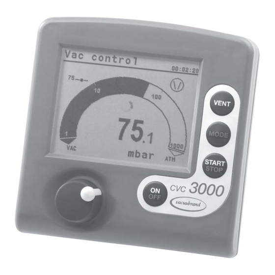
VARIO / VARIO-B pumps and pumping units and VARIO-SP pumps. When switching on the controller CVC 3000 for the very first time, a menu to select the language of the controller menu is displayed. Select the desired language (” Deutsch ”, ” English ”, ” Français ”) by turning the selection knob and press to confirm. - Page 11 page 10 of 42 00:00:00 Process runtime (only if process control is running) Vacuum control to a preset vacuum value (here 100 mbar/Torr/hPa) Pump down (continuous pumping) Pump symbol is displayed when pump is running. If a NT VARIO / VARIO-B pump is connected, the pump’s rotational speed in % is displayed. Time meter is running (in function ”VACUULAN”), remaining time in minutes is displayed.
-
Page 12: Notes On Operation
11 of 42 Rear side CVC 3000 venting connection connection power supply bushes for connection of an isolation serial interface or NT VARIO / VARIO-B valve and/or coolant valve RS 232 C pump or pumping unit and/or external pressure transducer... -
Page 13: Notes On Selecting The Function
12 of 42 Notes on selecting the function The controller CVC 3000 can be adapted to the specific application by choosing the appropriate function depending on the connected components. Automatic detection of the components: When switching on the controller, the actual configuration of the connected components is checked automatically. -
Page 14: Menu Guide
page 13 of 42 Menu guide (without NT VARIO / VARIO-B pump) Vac control Pump down Set vacuum 100 mbar Speed Hysteresis Auto Minimum Maximum Delay Delay Duration Duration - - - - - - Graphic - - - - - -- - - - - - - Graphic - - - - - - - - - - Back - - - - - - - - - - - - - Back - - - - - -... -
Page 15: Function Pump Down
page 14 of 42 Function Pump down ➨ ➨ ➨ ➨ ➨ Continuous pumping with pressure and time settings • Operation of a vacuum pump via in-line valve • Operation of a vacuum pump without in-line valve with VMS (Vacuum Management System, see ”Accessories”) •... - Page 16 page 15 of 42 Temporary switching from ”Pump down” to ”Vac control” or ”Auto mode” (only if control is running): ☞ Press key ”MODE”. The controller switches to function ”Vac control”, the current vacuum is used as set value. ☞ Only for VARIO NT pumps: Pressing key ”MODE” again switches to function ”Auto mode”. The con- troller adapts the boiling pressure starting with the current vacuum.
-
Page 17: Function Vac Control
page 16 of 42 Function Vac control ➨ ➨ ➨ ➨ ➨ Vacuum control to a preset vacuum value • Operation of a vacuum pump via in-line valve • Operation of a vacuum pump without in-line valve with VMS (Vacuum Management System, see ”Accessories”) •... - Page 18 page 17 of 42 The screen-shots show the factory-set values. Vac control Vac control 00:00:00 00:00:00 Set vacuum 100 mbar Set vacuum 100 mbar Speed Hysteresis Auto Maximum Maximum Delay Delay Duration Duration - - - - - - Graphic - - - - - - - - - - - - Graphic - - - - - - - - - - - - Back - - - - - - - - - - - - - Back - - - - - - -...
-
Page 19: Function Auto Mode (Pumps Nt Vario / Vario-B)
page 18 of 42 Function Auto mode (pumps NT VARIO / VARIO-B) ➨ Control of a NT VARIO / VARIO-B pump in operation mode auto mode: Automatic determination of the boiling vacuum and automatic adapting of the boiling vacuum also in case of changing process parameters. -
Page 20: Function Program
page 19 of 42 Function Program ➨ ➨ ➨ ➨ ➨ Ten programs with up to ten program steps with preset values for vacuum and time can be set and stored. ☞ Edit : Preset values for the process run can be edited: Time: Process runtime to reach a preset vacuum level or if setting ”Step”... -
Page 21: Example For Use
page 20 of 42 The number of the program with program step, the set vacuum, the actual vacuum and the runtime are displayed. The timeline in the diagram adapts automatically to the process time. ☞ Press the selection knob twice to return to the standard display. The last process (not in function VACUULAN) is stored in the temporary data memory as long as the controller stays switched on. - Page 22 page 21 of 42 Example 2 Vacuum pump with in-line valve and/or Vacuum-Management-System Module A: Pumping down with intermediate venting Program hh:mm:ss Vent. Step ATM ✔ ✔ 00:00:00 00:05:00 00:20:00 ✔ 00:21:00 ✔ 00:30:00 00:40:00 01:00:00 ATM ✔ ✔ 01:01:00 01:01:00 01:01:00 Program step 1 should be always a definite initial state, here atmospheric pressure.
-
Page 23: Function Vacuulan
22 of 42 Function VACUULAN ➨ ➨ ➨ ➨ ➨ Optimised vacuum control for vacuum networks (e. g. VACUUBRAND VACUU•LAN) • Operation of a vacuum pump via in-line valve • Operation of a vacuum pump without in-line valve with Vacuum-Management-System VMS •... -
Page 24: Examples For Use
page 23 of 42 Examples for use Assembly of a vacuum system ☞ Assemble vacuum connection lines between controller, vacuum pump (NT VARIO / VARIO-B pump or diaphragm pump with in-line valve or Vacuum-Management-System) and apparatus. ☞ Assemble electrical connections. ☞... -
Page 25: Vacuum For Distillation And Evaporation (E. G. Rotary Evaporator)
page 24 of 42 Vacuum for distillation and evaporation (e. g. rotary evaporator) Semi-automatic distillation and evaporation ☞ Select function ”Pump down”. ☞ Start process by pressing key ”START/STOP”. ☞ Observe process. As soon as evaporation starts, press key ”MODE” (switching to ”Vac control”). The vacuum level is kept constant (at the boiling pressure). -
Page 26: Vacuum For Vacuu•Lan Networks
page 25 of 42 ☞ When setting a value for ”Duration” , the controller switches off the pump when ”Duration” has passed even if a preset ”Minimum” has still not been reached. ☞ If neither ”Minimum” nor ”Duration” are preset, pumping down has to be finished by pressing key ”STOP”. -
Page 27: Function Configuration
page 26 of 42 Function Configuration In the menu ”Configuration” the device parameters are preselected. Preselections ☞ Use the selection knob to select the parameters. ☞ Adjustment : Adjustment of the pressure transducer under vacuum and/or at atmospheric pressure, see also section ”Readjustment”. Adjustment at atmospheric pressure is carried out at an absolute vacuum value between 1060 - 700 mbar and under vacuum at an absolute vacuum value between 0 - 20 mbar. -
Page 28: Readjustment
page 27 of 42 Readjustment The vacuum gauge was adjusted using factory standards, which are traceable through regular calibration in an accredited laboratory (German Calibration service) to the German national pressure standard. Depending on the process and/or accuracy re- quirements, check the adjustment and readjust if necessary. For readjustment, the device has to be adjusted both at atmospheric pressure as well as under vacuum but only if the reference pressures are certainly known. -
Page 29: Calibration In The Factory
Factory-set the read and write commands are completely compatible to the VACUUBRAND controller CVC 2000 (see section ”Read and write commands CVC 2000”). An extended instruction set is available using the command ”CVC 3” (see section ”Read and write commands CVC 3000”). Setting of the interface Set the interface parameters directly at the controller CVC 3000. -
Page 30: Read Commands Cvc 2000
page 29 of 42 Read commands CVC 2000 Function Command Response Description actual pressure IN_PV_1 XXXX mbar or unit according to preselections XXXX Torr or XXXX hPa actual frequency IN_PV_2 XX.X Hz device set IN_CFG XXXXX preselections 0: remote operation off 1: remote operation on 0: no automatic switch off 1: automatic switch off... -
Page 31: Write Commands Cvc 2000
page 30 of 42 Write commands CVC 2000 Function Command Parameter Description selected pressure OUT_SP_1 XXXX unit according to preselection (0001 to 1060 mbar (hPa) or 0001 to 0795 Torr) selected pressure OUT_SP_V XXXX unit according to preselection with venting* (0001 to 1060 mbar (hPa) or 0001 to 0795 Torr) selected frequency OUT_SP_2... -
Page 32: Read Commands Cvc 3000
31 of 42 Read commands CVC 3000 Function Command Response Description actual IN_PV_1 XXXX.X mbar/Torr/hPa unit according to preselections pressure actual speed IN_PV_2 XXX% 1-100% or HI time IN_PV_3 XX:XX h:m process runtime pressure IN_PV_X XXXX.X XXXX.X ...mbar pressure of all connected sensors... - Page 33 32 of 42 Read commands CVC 3000 Function Command Response Description Status IN_STAT XXXXXX process control 0 control off 1 pump down/ determinating boiling point 2 set pressure reached/ boiling pressure found 3 set pressure falls below/ Auto end switching off...
- Page 34 33 of 42 Read commands CVC 3000 Function Command Response Description IN_SP_1 XXXX mbar or set vacuum XXXX Torr or XXXX hPa IN_SP_2 XXX% maximum speed (100% = ”HI”) IN_SP_3 XXXX mbar or switching on pressure for VACUULAN or...
-
Page 35: Write Commands Cvc 3000
34 of 42 Write commands CVC 3000 Function Command Parameter Description operation mode OUT_MODE 0: VACUULAN Attention: If control 1: Pump down is running only 2: Vac control switching from 1 to 3: Auto mode 2, 2 to 3 and 3 to 2... - Page 36 *** After switching on, the controller is in ”CVC 2” mode by default. Send ”CVC 3” and ”STORE” to perma- nently set the controller’s RS 232C commands to the extended set ”CVC 3000”. Connection plug arrangement...
-
Page 37: Accessories
➨ To control a VACUUBRAND water jet pump (69 50 00) with solenoid operated valve with diode plug with a controller CVC 3000 instead of a controller CVC 2 / CVC 2 , the valve cable has to be replaced (see table). -
Page 38: Troubleshooting
page 37 of 42 Troubleshooting l l o c t i c t i e l l v i t i t c e l l y t i i l e i d i . y t " . " r i t c ' ' 0 y l t... -
Page 39: Cleaning The Pressure Transducer
page 38 of 42 e l l p i l r i f i t c V " : " l r i f . y r P " : " r i f i n i . y r a l l l l o l l o... -
Page 40: Notes On Return To The Factory
page 39 of 42 Notes on return to the factory Repair - return - DKD calibration Safety and health of our staff, laws and regulations regarding the handling of danger- NOTICE ous goods, occupational health and safety regulations and regulations regarding safe disposal of waste require, that for all pumps and other products the “Health and safety clearance form“... -
Page 41: Health And Safety Clearance Form
Tel.: +49 9342 808-0 - Fax: +49 9342 808-450 -Technology for Vacuum Systems- E-Mail: info@vacuubrand.de © 2001 VACUUBRAND GMBH + CO KG Printed in Germany Web: www.vacuubrand.com Documents are only to be used and distributed completely and unchanged. It is strictly the users´ responsibility to check carefully... - Page 42 Déclaration de conformité Vakuum-Controller / Vacuum controller / Régulateur de vide CVC 3000 (68 31 60) 100-230V Hiermit erklären wir, dass das oben bezeichnete Gerät in Konzeption und Bauart sowie in der von uns in Verkehr gebrachten Ausführung den grundlegenden Anforderungen der zutreffenden, aufgeführten EU- Richtlinien entspricht.
- Page 43 E-Mail: info@vacuubrand.de Web: www.vacuubrand.com © 2008 VACUUBRAND GMBH + CO KG Printed in Germany 99 91 18 Documents are only to be used and distributed completely and unchanged. It is strictly the users´ responsibility to check carefully the validity of this document with respect to his product. Manual-no.: 99 91 51 / 04/01/2008...
Need help?
Do you have a question about the CVC 3000 and is the answer not in the manual?
Questions and answers