vacuubrand CVC 3000 Instructions For Use Manual
Vacuum
Hide thumbs
Also See for CVC 3000:
- Instructions for use manual (80 pages) ,
- Instructions for assembly (12 pages) ,
- Instructions for use manual (43 pages)

Related Manuals for vacuubrand CVC 3000


Summary of Contents for vacuubrand CVC 3000
- Page 1 Technology for Vacuum Systems Vacuum Controller CVC 3000 Vacuum Controller Instructions for use Original instructions N°: 999151_EN_ONLINE...
- Page 2 +49 9342 808‑5550 ƒ Service +49 9342 808‑5660 Fax: +49 9342 808‑5555 E‑Mail: info@vacuubrand.com Web: www.vacuubrand.com Thank you for purchasing this product from VACUUBRAND GMBH + CO KG. You have chosen a modern and techni- cally high quality product. N°: 999151_EN_CVC3000_ONLINE/20.07.2017...
-
Page 3: Table Of Contents
Product description 3.1 Vacuum controller CVC 3000 ..... . 20 3.2 Functionality ........22 3.3 Operation modes . - Page 4 5.2.4 Menu display in general ..... . 40 5.3 Handling CVC 3000 ......41 Operation 6.1 Switch‑on/‑off controller .
- Page 5 10.2.3 Write commands (CVC 2000) ....107 10.2.4 Read commands (CVC 3000) ....108 10.2.5 Write commands (CVC 3000) .
- Page 6 First steps First steps (delivery status) First steps on delivery status Select language and units N°: 999151_EN_CVC3000_ONLINE/20.07.2017...
-
Page 7: Introduction
ƒ are intended to aid in your understanding of the proper use of the product. VACUUBRAND GMBH + CO KG reserves the right to modify ƒ or change the product design and/or technical specifications at any time without advanced notice. -
Page 8: About This Document
Please ask for replacement in case of an incomplete manual Contact us ƒ or download instructions for use on our web page: www.vacuubrand.com Contact us regarding any questions about this product, if you ƒ need further information, or to provide us with feedback. -
Page 9: Symbols And Icons
Introduction NOTICE Convention for additional notes Notice for a potentially harmful situation. Disregarding the notice could lead to material damage. Additional notes > Information or specific use recommendation, which must be IMPORTANT! observed. > Important information for the proper operation. Helpful tips and tricks >... -
Page 10: Handling Instructions (Action Steps)
Introduction Additional icons Positive example – Do! Negative example – References result – o. k. Do not! Refers to content of Refers to content of this manual. other documents. Handling or action Press selection knob or Turn selection knob key. Push and turn selection Push and hold key knob... -
Page 11: Abbreviations
Interface for an external peripheral device terms to connect with a VACUU·BUS capable ® vacuum gauge or ‑controller VACUU·BUS Bus system by VACUUBRAND. ® VACUU·CONTROL Web‑based application as remote control ® for vacuum controller and gauges made by VACUUBRAND. VACUU·LAN Local vacuum network for laboratories. -
Page 12: Safety Instructions
2.1 Working conditions Use the product only when it is in proper working condition. 2.1.1 Intended use The Controller CVC 3000 is a laboratory instrument, used to Intended use measure and/or control vacuum in therefore intended plants. The controller may only be used in non‑explosive areas and indoors. -
Page 13: Foreseeable Misuse
To put the controller completely into vacuum. ■ To immerse the controller into liquid or to blast it with steam. ■ To use the remote control VACUU·CONTROL with ® CVC 3000 without knowledge of the connected vacuum sys‑ tem. N°: 999151_EN_CVC3000_ONLINE/20.07.2017... -
Page 14: Target Groups
Safety instructions 2.2 Target groups Ensure that the controller is only operated by authorized and IMPORTANT! skilled personnel. Users need to have the corresponding skills and qualifications for doing the job listed in the table User permissions. 2.2.1 User permissions This manual must be read, understood and complied with by the person performing one of the following tasks: Supervising... -
Page 15: Safety Precautions
Safety instructions 2.3 Safety precautions Products of VACUUBRAND GMBH + CO KG are subject to high Quality standards and safety quality tests with goals for safety and operation. Prior to delivery each product has been tested thoroughly. 2.3.1 Protective clothing... - Page 16 >Repairs may only be performed by qualified personnel, e. g., service technician. CVC 3000 in combination with VACUU·CONTROL ® Option VACUU·CONTROL is a remote control for the controller. It is ®...
- Page 17 Peripherals and connected devices to the peripherals controller need to have the same or must have a higher ATEX approval. Without concordant categorization of peripherals, the specified category of the VACUUBRAND equipment loses its validity. Avoid ignition sources...
-
Page 18: Safety And Service
Safety instructions 2.4 Safety and service Safety regulations that apply to your work environment also apply Obligations for to persons who perform service works, especially in the handling service jobs of hazardous materials. 2.4.1 Meaning Health and Safety Clearance Products which are potentially hazardous may only be returned when all dangerous contaminations are removed. -
Page 19: Environmental Protection
ƒ media). Any more questions? We will help you: Phone: +49 9342 808‑5660 Fax: +49 9342 808‑5555 service@vacuubrand.com 2.5 Environmental protection NOTICE Risk of environmental damage due to incorrect disposal of the controller. Do not dispose your product in household waste! >... -
Page 20: Product Description
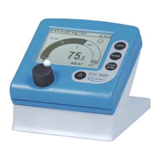
999151 Safety Information for Vacuum Equipment 999254 Origin packaging ‑‑‑‑‑‑ 3.1 Vacuum controller CVC 3000 The controller is designed for applications requiring controlled vacuum. The controller has a two‑point control mode to switch an in‑line isolation valve. The controller is freely programmable. Up to 10 programs can be stored in the controller memory. - Page 21 Product description Front Front panel Chemically resistant plastic housing Meaning LC display Control panel and product name Selection knob Rear side Rear side Ports for VACUU·BUS Meaning components ® Mains connection ` power supply unit ` VARIO diaphragm pump or ®...
-
Page 22: Functionality
Product description 3.2 Functionality The controller manages vacuum processes by controlling vacuum Functionality pumps, in‑line isolation‑ and/or air admittance valves. It controls process vacuum, cooling water and venting to demand. Valves and/or vacuum pumps are necessary to operate the controller. Without those components the controller can only be used as vacuum measurement device. -
Page 23: Operation Modes
Product description 3.3 Operation modes Up to 5 different operation modes are selectable at the controller. Specific modifications can be realized by indivudual mode me‑ nus. Selectable operation modes Pump down Standard ƒ Vac control ƒ Program ƒ Auto mode Optionally ƒ... -
Page 24: Installation And Connection
Installation and connection Installation and connection The controller is designed for installation directly at the workplace. > Observe all specifications for installation, connection and operation according to technical data, see chapter 10.1.1 Technical data. > Also observe rating plate data. Installation conditions The controller has acclimatized. -
Page 25: Built-In Version
Installation and connection 4.1.2 Built‑in version The CVC 3000 can be used as built‑in version fixed with spring clips; e. g., as front controller of a VARIO pump, built into a cable ® duct cover or into the cut‑out of a switch cabinet. -
Page 26: Examples Of Use
Vacuum hose Rotary evaporator Example CVC 3000 build‑up with cabinet dryer Wall power supply Controller CVC 3000, table top version Vacuum sensor (VSK) Cabinet dryer with control unit on top Vacuum valve Vacuum hose Diaphragm pump, vacuum pump N°: 999151_EN_CVC3000_ONLINE/20.07.2017... - Page 27 Installation and connection Example CVC 3000 directly mounted Wall power supply Controller CVC 3000, directly mounted VACUU·BUS cable ® Vacuum vessel, recipient Vacuum valve Vacuum hose Diaphragm pump, vacuum pump Install the controller as close as possible to the process in >...
-
Page 28: Connection
Installation and connection 4.2 Connection 4.2.1 Electrical connection Wall power supply kit* Power supply kit for CVC 3000 * short-circuit-proof multi-voltage power supply with integrated overload protection and changeable mains plugs. Prepare wall power supply plug 1. Take the wall power supply kit out of the packaging. - Page 29 > Plug female connection of the power supply cable into mains connection of the controller. Mains connection on the rear side Consider new connection design: For easy connection, the CVC 3000 Ports with guide of the newest series have a guide groove groove on the rear side for each port.
-
Page 30: Vacuum Connection
Installation and connection 4.2.2 Vacuum connection NOTICE Flexible vacuum hoses can contract because of evacuation. Fix vacuum hose at the connections. > > Fix connected components. > > Measure and trim the vacuum hose to a length that cares for >... - Page 31 Direct installation Flange connection (4) at vacuum chamber with sealing ring (5) ƒ ƒ and small flange (6) screwed to CVC 3000 fixed with clamping ring (7). Built‑in version (front mounting) Vacuum hose made of PTFE (9) – plugged on hose nipple, ƒ...
-
Page 32: Vacuu·bus
Y adapters make it possible to connect up to 32 accessory components. VACUU·BUS principle ® Example Principal sketch VACUU·BUS 1 CVC 3000 4 Vacuum sensor VSK ® componentc 2 Y adapter 5 Vacuum valve (In‑line valve) 3 Extension cable 6 Level sensor When connecting multiple, identical VACUU·BUS... - Page 33 Installation and connection VACUU·BUS components ® VACUU·BUS ® Vacuum sensor VSK 3000 636657 accessories VSP 3000 636163 (Option) Vacuum gauge VACUU·VIEW 683220 VACUU·VIEW extended 683210 Vacuum valve VV‑B 6 674290 (In-line valve) VV‑B 6C 674291 VV‑B 15C, KF 16 674210 VV‑B 15C, KF 25 674215 Coolant valve...
-
Page 34: Operating And Display Elements
Operating and display elements 5.1 Operating elements The operating elements are located on the controller front. controller figure see chapter 3.1 Vacuum controller CVC 3000 5.1.1 Selection knob The selection knob of the controller is a combination of rotary knob and push‑button. -
Page 35: Key Combinations
Operating and display elements – Select operation mode Mode Control panel keys ` With stopped operation: Mode menu for selecting the operation mode. – Change function/mode Mode ` During running operation: To switch from Pump down and further to Vac control Auto mode. -
Page 36: Display And User Interface
After booting the pressure display appears, including Bar graphic and preset operation mode. 5.2.1 Pressure display Example Display after switching on CVC 3000 Title bar (or status bar) Meaning Operation mode ‑ ` Pump down Mode ` Vac control... -
Page 37: Display Icons
Operating and display elements 5.2.2 Display icons When vacuum control has started additional icons appear on the display. When starting operation Icon Meaning Display symbols during operation Vacuum control is running (animation) Process time; runtime vacuum control (hh:mm:ss) Active component Icon Meaning Pump is running;... - Page 38 Operating and display elements Status display while operation is running Icon Meaning Icons for control Pump down – continous pumping status Pump down: lower pressure limit reached VACUU·LAN: pump down to set pressure Vac control: for 2‑point control – pump down to set pressure VACUU·LAN: pressure increase to switch on pressure Vac control: preset maximum exceeded VARIO control: pump down to set point.
-
Page 39: Signal Sounds (Warning Beep)
Operating and display elements Fault indication (warning symbol) Icon Meaning Error display Flashing: warning! When device connected to SUB‑D (Option) Icon Meaning Active connection to Controller in remote mode; controller only controllable RS232 port via connected PC or Notebook, local operation disabled. VACUU·CONTROL ‑adapter connected;... -
Page 40: Menu Display In General
Operating and display elements 5.2.4 Menu display in general The controller includes several menus and submenus, e. g., Configuration, Function, Display..Submenu Example Submenu Configuration Meaning Titel bar ` Menu name Menu interface ` Selectable functions or submenus (on the right side of the display) ` Adaptable value or ` selectable content Back (return) -
Page 41: Handling Cvc 3000
Operating and display elements 5.3 Handling CVC 3000 The handling of the controller is menu‑driven. Menus are ac‑ Handling and cessed via push buttons on the control panel or via key combina‑ Operation tions. Use the selection knob to select function or menu. - Page 42 Operating and display elements Input (data entry) Changeable values are positioned on the right side in the display. Text on the ride side accords to content selection like in a drop down list. Exception: menu Program, in this menu data and value are editable. Example: enable entry and edit 1.
-
Page 43: Operation
Operation Operation 6.1 Switch‑on/‑off controller Switch‑on Switch‑on CVC 3000 CVC 3000 V2.xx 5 Initial screen: company logo and firmware version, for approximately 2 seconds. 5 Pressure graphic is displayed. Switch‑off > Press key On/Off Switch‑off CVC 3000 5 Controller switched off (display off). -
Page 44: Select Language And Pressure Unit
Operation 6.2 Select language and pressure unit Select language and pressure unit 櫓匡 櫓匡 CVC 3000 V2.xx 5 Initial screen. N°: 999151_EN_CVC3000_ONLINE/20.07.2017... -
Page 45: Mode - Operation Mode
Operation 6.3 Mode – Operation mode The controller is supplied with several operating modes. Only when the controlling process is stopped it is possible to select an operation mode. 6.3.1 Select operation mode Example Call‑up mode menu 5 Title bar shows the selected operation mode (Mode). Select any other operation mode in the same way as described above for control. -
Page 46: Mode Menu
Operation 6.3.2 Mode menu Mode menu display Example Menu description Title bar menu name Meaning and operation modes Selectable operation modes Pump down ` Continous pump down or ` pump down with pressure and time presetting. ` VARIO : Pump down with adjustable motor speed (pumping ®... -
Page 47: Start Controlling
Start vacuum controlling after selecting the required operation mode. The controller works in delivery status with the default set‑ tings of the factory setting. Start controlling Example Start CVC 3000 5 Controller starts. 5 Icons are displayed. 6.5 Control during operation 6.5.1 Venting (VENT) - Page 48 Operation Venting VENT button is used to vent the system. A short click on this button will momentarily vent the system as the process contin‑ ues. Holding the VENT key for longer than 2 seconds will cause the system to be vented to atmospheric pressure and the pump will stop running;...
-
Page 49: Change Operation Mode
Operation 6.5.2 Change operation mode During running operation the operation mode can be switchted between by pressing Pump down, Vac control Auto mode Mode key. Switch mode during running operation Examples Switch mode Pump down ↓ Vac control 5 Operation mode switched to control. - Page 50 Operation Switch back from Vac control Pump down. Switch back to primary mode 5 Title bar displays Pump down. Typical applications Pump down control: Semiautomatic distillation. Recommended for applications for which the process vacuum is still to be determined. Firstly the vacuum pump is pumping down rapidly in mode Pump down.
-
Page 51: Display Graphic (Curve)
Operation 6.5.3 Display graphic (curve) In addition to the bar graphic of the pressure display the display Pressure history Graphic can be switched to a diagram named which shows a pressure vs. time curve. That Graphic curve will only be displayed while operation is run‑ ning. -
Page 52: Quit Display Graphic
Operation Graphic menu Description pressure history display Header Meaning ` Active operation mode. ` Vacuum set point; for Vac control Auto mode. ` Actual vacuum value (actual pressure). ` Eelapsed process time. Axis – pressure ` Unit according to pre‑settings (mbar, Torr, hPa). Pressure graph ` Pressure/time progress. -
Page 53: Quick Adaption During Operation
Operation 6.6 Quick adaption during operation 6.6.1 Set vacuum Vac control In mode the set vacuum can be adapted directly du‑ ring running operation. Adapt set vacuum fine tuning 1 detent = 1 pressure value (mbar, Torr, hPa) Example Adapt set vacuum fine tuning 5 Controller controls to new set vacuum. -
Page 54: Motor Speed (Only Vario ® )
5 Pump icon with percentage value. 5 VARIO pump runs with adjusted motor speed. ® 6.7 Stop control Stop control Example Stop CVC 3000 5 Controller and vacuum control stops. 5 Display icons switched off. N°: 999151_EN_CVC3000_ONLINE/20.07.2017... -
Page 55: Advanced Menus And Operation
Advanced menus and operation Advanced menus and operation 7.1 Operation menus A selected operation mode can be adapted and optimized for the Optimizing operation process through the corresponding operation menu. The settings mode in an operation menu include mainly: motor speed, set vacuum or time presettings. -
Page 56: Pump Down
Advanced menus and operation 7.1.1 Pump down Continous pump down with pressure and time presettings. Meaning Menu – Pump down Example Operation menu Pump down Parameter Meaning Parameter Pump down Speed (%) VARIO : Speed settings for pump down. ®... -
Page 57: Vac Control
Advanced menus and operation 7.1.2 Vac control Control to a set vacuum value. Meaning Menu – Vac control Example Operation menu Vac control Parameter Meaning Parameter Vac control Set vacuum Setting for lower vacuum level for 2‑point control (mbar) or precisely for VARIO pump. -
Page 58: Auto Mode
Advanced menus and operation Hysteresis values Auto Factory settings Set vacuum 900 1000 (mbar) Hysteresis Hysteresis (mbar) 7.1.3 Auto mode (only valid for VARIO pump) ® Automatic detection and tracking of boiling point, unaffected by Meaning varying process conditions. Menu – Auto mode ... -
Page 59: Program
Advanced menus and operation Application example – rotary evaporator Minimum to prevent rotary evaporator from receiving re‑eva‑ Application example poration from the flask. Set Minimum value to the vapor pressure for Auto mode of the solvent at ambient temperature. 7.1.4 Program Up to 10 individual programs including vacuum and time preset‑... -
Page 60: Vacuulan
Advanced menus and operation 7.1.5 VACUULAN Vacuum control, optimized for VACUU·LAN vacuum networks ® Meaning by VACUUBRAND. Menu VACUULAN Example VACUULAN display Parameter Meaning Parameter VACUULAN Set vacuum Setting for lower vacuum level, which shall be reached easily when the vacuum network is not (mbar) used. -
Page 61: Program Functions
Advanced menus and operation 7.2 Program functions In menu Program presettings for up to 10 different application Meaning scenarios can be stored. Program for frequently used applications. 7.2.1 Open/Change program Example Open Program 2 N°: 999151_EN_CVC3000_ONLINE/20.07.2017... -
Page 62: Edit Program
Advanced menus and operation 5 Controller is running with settings of program 2. 5 Program 2 displayed in title bar. 7.2.2 Edit program Open program editor Example Call up program editor Auto N°: 999151_EN_CVC3000_ONLINE/20.07.2017... - Page 63 Advanced menus and operation Explanation program editor Example Menu explanation Title bar menu name ` Number 1–10, sequence of program steps. hh:mm:ss Timer for individual program steps: ` Until vacuum value has been reached. ` Hold vacuum level. ` Preset a vacuum level. Vent.
- Page 64 Advanced menus and operation Adjustable parameters Adjustable program hh:mm:ss 00:00:00–99:59:59 step parameters 0–1060; ATM (Torr: 0–795; ATM) ATM = atmosphere; this starting point is always attainable. Vent. Step* Auto* Pump down and boiling point de‑ tection within the preset time in‑ terval regarding changing process conditions.
- Page 65 Advanced menus and operation Create a program NOTICE Input only enabled for 5 seconds. The time frame for inputs is 5 seconds. If this time expires wi‑ thout any input, the edit frame (= input enabled) returns to bar marking. Only input confirmed by selection knob will be stored. First of all write down the complete program.
- Page 66 Advanced menus and operation Example Create a new program 5. Turn the selection knob to set the required vacuum value, e. g., and then press selection knob to confirm input. 5 For settings Vent Step will be set automatically and setting for will be skipped.
- Page 67 Advanced menus and operation 8. Turn the selection knob to set the required vacuum value, e. g., 10 mbar. Afterwards press selection knob repeatedly until the bar marking is placed onto program step 03. 9. For further input do like described above for program step 01 and 02.
-
Page 68: Store Program
Advanced menus and operation 7.2.3 Store program Store the edited program under a free program number. IMPORTANT! > > Store program under a program number Example Store program Auto Auto N°: 999151_EN_CVC3000_ONLINE/20.07.2017... -
Page 69: Display During Operation
Advanced menus and operation Example Store program 5 Program stored under program number 5. 5 Display switches to pressure display. 7.2.4 Display during operation As long as a program is running, the title bar displays additionally the current program step, e. g., Program 1 in program step 02. Program display during operation ... -
Page 70: Program Memory
Example: Test procedure for a new substance 20 l parallel evaporator and vacuum apparatus: Example Test assembly Vacuum controller CVC 3000, in‑line suction valve, chemistry dia‑ phragm pump MD 4C NT. In mode Pump down the parallel evaporator was quickly eva‑... - Page 71 Advanced menus and operation How to use program memory 1. Press Mode key. Test values in temporary buffer 2. Turn selection knop to select Program. 5 Title bar: Program 3. Open the program editor. 5 Listet values of the latest run test set‑up appear. as first and last program step.
-
Page 72: Program Examples
Advanced menus and operation 7.2.6 Program examples Example 1 Vacuum pump with in‑line isolati‑ Example 1 on valve: Linear pump down to 500 mbar N° Program step Liniear pump down to 500 mbar within 3 minutes. Limited re‑ producibility because of the undefined initial state. 02 ‑10 not used. - Page 73 Advanced menus and operation Because of the check mark at Step the controller is venting the system as quickly as possible to ATM. Control stops after 1 mi‑ nute. 05 ‑10 not used. Example 3 Vacuum pump with in‑line iso‑ lation valve and/or Vacuum Management System VMS B: Pump down with intermediate...
-
Page 74: Sample Form For Program
Advanced menus and operation 7.2.7 Sample form for program When loading the factory settings, the data stored in the IMPORTANT! program memory will be deleted. Keep important program settings and make note of the > > values that are listed in the program editor. N°: 999151_EN_CVC3000_ONLINE/20.07.2017... -
Page 75: Configuration Menu
Advanced menus and operation 7.3 Configuration menu In menu Configuration the controller parameters are set. This Meaning menu is also for adjusting the vacuum sensor and for loading Defaults settings. Call up Configuration menu Example Call up Configuration menu Configuration menu displayed. -
Page 76: Content Selection
Advanced menus and operation 7.3.1 Content selection Configuration The following menu items of can be selected, ac‑ Specified content tivated and used. Defaults Selection Meaning Defaults (standard) Cancel Leave menu item without default setting. Load Load default settings. Defaults Load is activated all controller parameter will be IMPORTANT! reset to delivery status. -
Page 77: Submenus
Advanced menus and operation Adjustment Selection Meaning Sensor adjustment function 1060–700 Adjustment range of a vacuum sensor, internal or ex‑ 20–0 ternal at atmospheric pressure (1060–700) or under vacuum (20– ~0). For further descriptions about sensor adjustment see chapter: 9.2 Sensor readjustment 7.3.2 Submenus Submenu –... - Page 78 Advanced menus and operation Submenu – Sensors In submenu Sensors all connected sensors are listed. The inter‑ nal sensor is generally displayed as Sensor. External sensors are listed with sensor type name and address. Submenu Sensors Display Meaning Sensor selection Inverse Sensor = currently selected for pressure display.
- Page 79 Advanced menus and operation Submenu – RS‑232 Submenu RS-232 is applied for interface configuration, parame‑ ter adjustments and commands. see also chapter: 10.2 Interface commands. Submenu RS232 Parameter Selection Meaning Adjustable RS232 parameter Baud 19200 Default setting for transmission speed. The baud rate of data transfer of trans‑...
-
Page 80: Function Menu
Advanced menus and operation 7.4 Function menu Function menu is not for every day use but for special controller Meaning parameters, like VACUU·BUS address assignment or updates. ® Call up Function menu Example Call up Function menu 0T 00:00:00 1234567 140408 Function... -
Page 81: Content Selection
Advanced menus and operation 7.4.1 Content selection Function The following menu items of can be selected and/or Specified content loaded. int. Air V. Internal air Selection Meaning admittance valve Auto Internal venting valve does not switch, if an external (venting valve) venting valve or vacuum sensor is connected to the controller. - Page 82 Advanced menus and operation Update Firmware update Selection Meaning Cancel Quit menu item without updating. Load Load controller firmware update. Defaults Selection Meaning Default settings for Service Cancel Quit menu item without default setting. Normal Load default settings – including presettings for 1–3 sta‑ ge VARIO pumps or for pumping units or for table top ®...
-
Page 83: Submenu Vacuubus (Address Assignment)
Advanced menus and operation 7.4.2 Submenu Vacuubus (address assignment) NOTICE VACUU·BUS components always need to be configurated, ® if several components of the same type are to be connected, e.g., 3 external sensors VSK type. Configuration is equivalent to address assignment. Address assignment (configuration) Several VACUU·BUS components of the same type, which... - Page 84 Advanced menus and operation Assign a new address number to a VACUU·BUS component ® In the following example a second VSK type sensor receives VSK2 as new communication address code. A new address can be assigned only individually. IMPORTANT! > Connect only the VACUU·BUS component to the control‑...
- Page 85 Advanced menus and operation Example VACUU·BUS assignment 5 frame marking 5 New communication address code for second sensor VSK = VSK2 N°: 999151_EN_CVC3000_ONLINE/20.07.2017...
-
Page 86: Possible Address Configurations
Advanced menus and operation 7.4.3 Possible address configurations **Address VACUU·BUS elements Abbreviation N° 1–4 Isol.v. _ In‑line suction valve Address table VACUU·BUS 1–4 Waterv. _ Coolant valve components 1–4 Air V. _ Venting valve (air admittance valve) 1–4 VMS _ VMS module Fault indicator Error... -
Page 87: Differential Pressure Measurement
Advanced menus and operation 7.5 Differential pressure measurement A differential pressure between two pressure sensors can be Meaning determined and displayed between the internal pressure sen‑ sor and an external sensor or between two external sensors see chapter: 7.4.2 Submenu Vacuubus (address assignment). -
Page 88: Resolving Problems
Resolving problems Resolving problems Technical support > To identify errors and potential remedies, please refer to the Technical support troubleshooting table: Fault – Cause – Remedy. In case you need additional assistance, please contact our Service department. 8.1 Error display The major symbol for fault indication is the warning triangle. - Page 89 Resolving problems Combinations of flashing display icons Icon flash rate Fault and Meaning beep when Sound ` Limit pressure reached ` Overpressure ` Process time elapsed ` Venting valve ` In‑line suction valve ` Coolant valve ` External sensor removed ` or defective ` internal sensor defective ` Vario pump...
-
Page 90: Fault - Cause - Remedy
Resolving problems 8.2 Fault – Cause – Remedy Fault ` Possible cause Personnel Remedy User, Sensitive process not Motor speed too high. Reduce motor speed. ƒ ƒ Specialist controllable Pumping speed too high. ƒ respon. Frequent error messa‑ Several controllers are Use only one controller for ƒ... - Page 91 Resolving problems Fault ` Possible cause Personnel Remedy User, In‑line suction valve icon In‑line suction valve remo‑ Check the connection. ƒ ƒ Specialist flashes ved. Check plug connection. ƒ Plug disconnected. ƒ Replace defective parts. ƒ In‑line suction valve ƒ...
- Page 92 Resolving problems Fault ` Possible cause Personnel Remedy Specialist No display Controller switched off. Switch on the controller; ƒ ƒ On/Off key. Power supply disconnec‑ ƒ ted. Check plug connection and ƒ wall power supply for cor‑ Power supply not cor‑ ƒ...
- Page 93 Resolving problems Fault ` Possible cause Personnel Remedy User, Sensors submenu is Submenu Sensors... does Select the required sen‑ ƒ ƒ Specialist permanently displayed not automatically switch sor by turning and pressing back to previous display. selection knob. respon. After loading defaults Special factory settings Set language and pressure...
-
Page 94: Controller Reset
Resolving problems 8.3 Controller Reset Auto reset The following error indications will be reset automatically with Automatic reset remedy: Overpressure ƒ Process time elapsed ƒ Limit pressure reached ƒ Error air admittance valve ƒ Error Peltronic ƒ Active reset Several error indications need to be reset manually. Depending Reset after action on the fault severity different actions are required. - Page 95 Resolving problems IMPORTANT! Note the settings of stored programs, before loading Default. > > Load Default settings Load factory settings N°: 999151_EN_CVC3000_ONLINE/20.07.2017...
-
Page 96: Error Of External Components
Resolving problems Load factory settings 8.4 Error of external components Error messages for defective external components such as In‑ line suction valve, vacuum sensor, etc. cannot be reset. > Replace defective accessories or > send defective accessories for repair to your local supplier or to our Service. -
Page 97: Cleaning And Maintenance
Cleaning and maintenance Cleaning and maintenance 9.1 Cleaning This chapter does not contain descriptions for the deconta‑ IMPORTANT! mination of the controller. This chapter describes only simple cleaning and care measures. 9.1.1 Controller Clean surface > Clean soiled surface with a clean, slightly wetted cloth. To moisten the cloth we recommend water or mild soap. -
Page 98: Sensor Readjustment
Cleaning and maintenance 9.2 Sensor readjustment NOTICE For readjustment the reference pressures need to be known with certainty In the pressure range 20 – 700 mbar (15 – 525 Torr) no adjustment is possible. Check the accuracy of the pressure sensor in case of irre‑ >... - Page 99 Cleaning and maintenance Adjustment under vacuum An adjustment under vacuum is only possible if the pressure is Adjustment under vacuum lower than < 20 mbar (< 15 Torr) absolute. 1. Evacuate the measurement connection of the controller or in case the connected external vacuum sensor VSK 3000 to a pressure <...
- Page 100 Cleaning and maintenance Adjustment at a reference pressure Instead of adjustment under vacuum to a pressure < 0,1 mbar Adjustment at (< 0.1 Torr), adjustment to a precisely known reference pressure reference pressure within the range of 0 – 20 mbar (0 – 15 Torr) is possible. 1.
-
Page 101: Appendix
108 mm x 58 mm x 34 mm 4.3 in. x 2.3 in. x 1.4 in. Weight 300 g 0.66 lb Mains plug AC, changeable: EU/UK/US/AUS Electrical data – CVC 3000 (US) Supply voltage, max. 24 VDC (±10 %) 24 VDC (±10 %) Power, max. 3,4 W 3.4 W... - Page 102 DN 6/10 Venting Hose nozzle for flexible tube = 4–5 mm Vacuum data (only differing data) Technical data package for fine CVC 3000 with external VSP 3000 (US) vacuum control Measuring range, absolute 1000–1x 10 mbar 750–1x 10 Torr ‑3...
-
Page 103: Product Comparison Cvc 3000
5 in. x 5 in. x 3.5 in. Dimensions with foot 144 mm x 124 mm x 115 mm 6 in. x 5 in. x 4.5 in. * without wall power supply 10.1.2 Product comparison CVC 3000 Product comparison CVC 3000 Product name CVC 3000 ‑... -
Page 104: Rating Plate
Service department, name us product > > type and serial number. With this information we can offer selective support and advice for your product. Rating plate CVC 3000 Rating plate Manufacturer Type/Date of construction/Month Serial number Power supply Electrical power Compatible to VACUU‑BUS... -
Page 105: Interface Commands
CVC 2000 are able to communicate with CVC 3000 (pay attention to interface stettings). The advanced command set of CVC 3000 can be used for full functionali‑ ty (switch by CVC 3<CR>). CVC 3000 commands which are not listed for CVC 2000 also work for CVC 2000 command set (e. -
Page 106: Read Commands (Cvc 2000)
Appendix 10.2.2 Read commands (CVC 2000) Command Operation Reply Description IN_PV_1 actual pressure XXXX unit corresponding to default settings mbar/hPa/Torr IN_PV_2 motor speed XX.X Hz actual motor speed IN_CFG default settings 0XXXX VACUU·LAN 1XXXX continuous pumping 2XXXX controlling without auto mode 3XXXX controlling by auto mode 4XXXX... -
Page 107: Write Commands (Cvc 2000)
Appendix 10.2.3 Write commands (CVC 2000) Command Operation Parameter Description OUT_MODE operation mode continuous pumping controls without auto mode controls by auto mode optional: sensitivity: low optional: sensitivity: normal optional: sensitivity: high program OUT_SP_1 set vacuum XXXX unit corresponding to default settings (mbar/ hPa/Torr);... -
Page 108: Read Commands (Cvc 3000)
Appendix 10.2.4 Read commands (CVC 3000) Command Operation Reply Description IN_PV_1 actual pressure XXXX.X unit corresponding to default settings; (X.XEXX for Pirani) with decimal place for VSK or exponenti‑ mbar/hPa/Torr ally for Pirani IN_PV_Sx actual pressure XXXX.X pressure of sensor x, vacuum sensor x (X.XEXX for Pirani) - Page 109 Appendix Command Operation Reply Description XXXXXXXX1XXXXXXX IN_CFG pre‑settings coolant valve connected XXXXXXXXX0XXXXXX air admittance valve not connected XXXXXXXXX1XXXXXX air admittance valve connected XXXXXXXXXX0XXXXX fault indicator not connected XXXXXXXXXX1XXXXX fault indicator connected XXXXXXXXXXX0XXXX level sensor not connected XXXXXXXXXXX1XXXX level sensor connected XXXXXXXXXXXX0XXX remote module not connected XXXXXXXXXXXX1XXX...
- Page 110 (0..9) IN_SP_P4y step no step in program step y (0..9) step in program step y (0..9) IN_SP_P5y auto no auto in program step y (0..9) auto in program step y (0..9) IN_VER version CVC 3000 VX.XX software version N°: 999151_EN_CVC3000_ONLINE/20.07.2017...
-
Page 111: Write Commands (Cvc 3000)
Appendix 10.2.5 Write commands (CVC 3000) Command Operation Parameter Description OUT_MODE operation mode VACUU·LAN continuous pumping vac control auto mode optional: sensitivity: low optional: sensitivity: normal optional: sensitivity: high program OUT_CFG restart searching yXXX y: 0..D: language+ (hexadecimal), see: Vacuubus device... - Page 112 CVC 2000 commands CVC 3000 commands**** **** After being switched on, the controller is in CVC 2 mode by default. Send CVC 3 and STORE to per- manently set the controller RS 232C commands to the extended set CVC 3000. OUT_VENT ‑‑‑...
-
Page 113: Ordering Information
Vacuum controller Order‑N° Ordering information CVC 3000 table top version 683160 CVC 3000 built‑in version 636595 CVC 3000 + VSP 3000 (package for fine vacuum control) 635983 Spare parts Order‑N° Ordering information spare parts Vacuum sensor (vacuum gauge head) VSK 3000, 1080‑0,1 mbar... - Page 114 Purchase original accessories and spare parts from your spe‑ International sales offices and cialized distributor or through international sales offices of specialized trade VACUUBRAND GMBH + CO KG. Information about the complete product range are available > > in the current product catalog.
-
Page 115: Service
Appendix 10.4 Service Take advantage of the comprehensive service range of Service range VACUUBRAND GMBH + CO KG. Service in detail Product guidance and practical solutions, ƒ fast delivery of spare parts and accessories, ƒ professional maintenance, ƒ immediate repairs processing, ƒ... -
Page 116: Glossary
Smartphones. With the new LAN or WLAN adapter all pumping units and vacuum systems equip‑ ped with the CVC 3000 vacuum controller or a DCP 3000 vacuum gauge can be integrated into a computer network. -
Page 117: Index
... . 62 CVC 3000 ....int. Air V....81 Program examples . - Page 118 Submenu Sensors ..78 Submenu Vacuubus ..83 Switch‑on CVC 3000 ..43 Switch‑on/‑off ... . . 43...
-
Page 119: Certifications
Bevollmächtigter für die Zusammenstellung der technischen Unterlagen / Person authorised to compile the technical file / Personne autorisée à constituer le dossier technique: Dr. J. Dirscherl · VACUUBRAND GMBH + CO KG · Alfred‑Zippe‑Str. 4 · 97877 Wertheim · Germany Ort, Datum / place, date / lieu, date: Wertheim, 20.07.2017 ppa. -
Page 120: Us/Can Certificate
Appendix 10.7.2 US/CAN Certificate N°: 999151_EN_CVC3000_ONLINE/20.07.2017... -
Page 121: Declaration Of Conformity - China Rohs 2
10.7.3 Declaration of Conformity – China RoHS 2 DECLARATION OF CONFORMITY – China RoHS 2 VACUUBRAND GMBH + CO KG has made reasonable efforts to ensure that hazardous mate‑ rials and substances may not be used in its products. In order to determine the concentration of hazardous substances in all homogeneous materials of the subassemblies, a “Product Conformity Assessment”... - Page 122 (Pb), mercury (Hg), cadmium (Cd), hexavalent chromium (Cr+VI), polybrominated biphenyls (PBB), and polybrominated diphenyl ethers (PBDE). Products manufactured by VACUUBRAND may enter into further devices (e.g., rotary evaporator) or can be used together with other appliances (e.g., usage as booster pumps).
- Page 123 N°: 999151_EN_CVC3000_ONLINE/20.07.2017...
- Page 124 Technology for Vacuum Systems Manufacturer: VACUUBRAND GMBH + CO KG Alfred‑Zippe‑Str. 4 97877 Wertheim GERMANY Phone: ƒ Head office +49 9342 808‑0 ƒ Sales +49 9342 808‑5550 ƒ Service +49 9342 808‑5660 Fax: +49 9342 808‑5555 E‑Mail: info@vacuubrand.com Web: www.vacuubrand.com...
Need help?
Do you have a question about the CVC 3000 and is the answer not in the manual?
Questions and answers