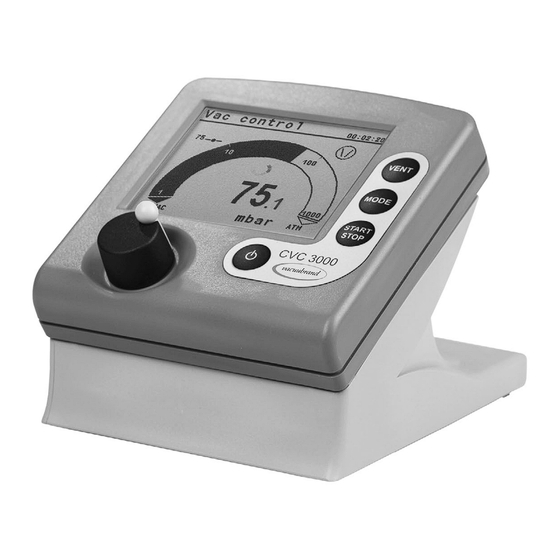
vacuubrand CVC 3000 Instructions For Use Manual
Vacuum controller
Hide thumbs
Also See for CVC 3000:
- Instructions for use manual (124 pages) ,
- Instructions for assembly (12 pages) ,
- Instructions for use manual (43 pages)

Related Manuals for vacuubrand CVC 3000


Summary of Contents for vacuubrand CVC 3000
- Page 1 1 of 80 Technology for Vacuum Systems Instructions for use CVC 3000 Vacuum controller...
- Page 2 VACUU•LAN (US-Reg.No 3,704,401), VACUU•BUS , VACUU•CONTROL ® ® ® Peltronic , VARIO (US-Reg.No 3,833,788), VACUUBRAND (US-Reg.No ® ® ® 3,733,388) and also the shown company logos are registered trademarks of VACUUBRAND GMBH + CO KG in Germany and/or other countries.
- Page 3 page 3 of 80 Achtung: Die vorliegende Betriebsanleitung ist nicht in allen EU-Sprachen verfügbar. Der Anwender darf die beschriebenen Geräte nur dann in Betrieb nehmen, wenn er die vorliegende Anleitung versteht oder eine fachlich korrekte Übersetzung der voll- ständigen Anleitung vorliegen hat. Die Betriebsanleitung muss vor Inbetriebnahme der Geräte vollständig gelesen und verstanden werden, und alle geforderten Maß- nahmen müssen eingehalten werden.
- Page 4 page 4 of 80 Bemærk: Denne manual foreligger ikke på alle EU sprog. Brugeren må ikke be- tjene apparatet hvis manualen ikke er forstået. I det tilfælde skal en teknisk korrekt oversættelse af hele manual stilles til rådighed. Manual skal være gennemlæst og forstået før apparatet betjenes og alle nødvendige forholdsregler skal tages.
- Page 5 page 5 of 80 Figyelem! Ez a kezelési utasítás nem áll rendelkezésre az EU összes nyelvén. Ha a felhasználó nem érti jelen használati utasítás szövegét, nem üzemeltetheti a készüléket. Ez esetben a teljes gépkönyv fordításáról gondoskodni kell. Üzembe helyezés előtt a kezelőnek végig kell olvasnia, meg kell értenie azt, továbbá az üzemeltetéshez szükséges összes mérést el kell végeznie.
- Page 6 page 6 of 80 Attentie: Deze gebruiksaanwijzing is niet in alle talen van de EU verkrijgbaar. De gebruiker moet niet met dit apparaat gaan werken als voor hem/haar de gebruiks- aanwijzing niet voldoende duidelijk is. Bij gebruik van deze apparatuur is het nood- zakelijk een technisch correcte vertaling van de complete gebruiksaanwijzing te hebben.
- Page 7 page 7 of 80 Varning: Denna instruktion är inte tillgänglig på alla språk inom EU. Användaren får inte starta utrustningen om hon/han inte förstår denna instruktion. Om så är fallet måste en tekniskt korrekt instruktion göras tillgänglig. Instruktionen måste läsas och förstås helt före utrustningen tas i drift och nödvändiga åtgärder göres.
-
Page 8: Reset / Language Selection
page 8 of 80 Reset / Language selection press both switch off C V C 30 00 V 2. 0 D eut sch P or t uguê E ngl i sh Ρ y ccк ий Fr ança i s P ol ski I t al i ano N ed erl . -
Page 9: Table Of Contents
page 9 of 80 Contents Reset / Language selection ..........8 Safety information! ............11 Important information! ................11 General information ................13 Intended use..................13 Setting up and installing the equipment ..........14 Ambient conditions ................15 Operating conditions ................. 16 Safety during operation .............. - Page 10 Interface parameters ............61 Setting of the interface ..............61 Read commands ”CVC 2000” ............62 Write commands ”CVC 2000” ............63 Read commands ”CVC 3000” ............65 Write commands ”CVC 3000” ............67 Accessories ..............69 Troubleshooting ............... 71 Repair - Maintenance - Return - Calibration ....
-
Page 11: Safety Information
Make operating personnel aware of dangers arising from the equipment and the processed substances. VACUUBRAND disclaims any liability for inappropri- ate use of this controller and for damage from failure to follow instructions contained in this manual. - Page 12 page 12 of 80 ➨ DANGER indicates a hazardous situation which, if not avoided, will result in death or serious injury. + WARNING indicates a hazardous situation which, if not avoided, could result in death or serious injury. • CAUTION indicates a hazardous situation which, if not avoided, could result in minor or moderate injury.
-
Page 13: General Information
page 13 of 80 General information Remove all packing material from the packing box. Re- NOTICE move the product from its packing-box and retain all pack- aging until the equipment is inspected and tested. Inspect the equipment promptly and carefully. If the equipment is damaged, notify the supplier and the carrier in writing within three days. -
Page 14: Setting Up And Installing The Equipment
page 14 of 80 +40°C), or for short periods up to +176°F (+80°C) at the pressure transducer (gas temperature). Periodical- ly check maximum temperatures if installing the con- troller in a cabinet or a housing. Make sure ventilation is adequate to maintain recommended operating tem- perature. -
Page 15: Ambient Conditions
Avoid high heat supply (e.g., due to hot process gases). Position the controller CVC 3000 and its vacuum line in such a way that condensate cannot flow towards the pres- sure transducer. -
Page 16: Operating Conditions
page 16 of 80 • Do not operate this product near flames. To the best of our knowledge the equipment is in com- NOTICE pliance with the requirements of the applicable EC-direc- tives and harmonized standards (see ”Declaration of Con- formity”) with regard to design, type and model. -
Page 17: Safety During Operation
page 17 of 80 Safety during operation ➨ Adopt suitable measures to prevent the release of dangerous, toxic, explosive, corrosive, noxious or pol- luting fluids, vapors and gases. + Never operate this controller if it has a damaged cord or plug. If the controller is not working properly, has been dropped or has fallen into water, contact your service provider. -
Page 18: Maintenance And Repair
page 18 of 80 Maintenance and repair ➨ Switch off the controller. Disconnect the power supply and wait five seconds before starting mainte- nance to allow the capacitors to discharge. ➨ Note: The equipment may be contaminated with chem- icals, which have been processed during operation. Ensure that the controller is completely decontaminat- ed before maintenance commences. -
Page 19: Important Information: Equipment Marking (Atex)
The overall category of the equipment depends on the connected com- ponents. If the connected components do not comply with the classifi- cation of the VACUUBRAND equipment, the specified category of the VACUUBRAND equipment is no longer valid. Vacuum pumps and vacuum gauges in category 3 are intended for con- nection to equipment in which during normal operation explosive atmo- spheres caused by gases, vapors or mists normally don’t occur;... - Page 20 page 20 of 80 • The equipment is designated for an ambient and gas inlet temperature during operation of +10 to +40°C. Never exceed these ambient and gas inlet temperatures. If pumping / measuring gases which are not potentially explosive, extended gas inlet temperatures are permissible. See instructions for use, section “Gas inlet temperatures”...
-
Page 21: Technical Data
21 of 80 Technical data Technical data of controller Controller CVC 3000 ceramic diaphragm (alumina), Pressure transducer capacitive, absolute pressure, gas type independent Display LCD graphic display, illuminated Pressure units / scale (selectable) Torr, mbar or hPa Measuring range (absolute) 810 - 0.1 Torr (1080 - 0.1 mbar) -
Page 22: Technical Data Of Power Supply
22 of 80 Controller CVC 3000 Venting connection hose nozzle for hose I.D. 3/16” (4-5 mm) Maximum admissible pressure at vent- 17.4 psi (1.2 bar) absolute ing connection Interface RS-232 C Weight with / without foot 1.25lbs. (0.57kg) / 0.97lbs. (0.44kg) Dimensions L x W x H approx. -
Page 23: Wetted Parts
PPS / glass fiber Sensor seal Chemically resistant fluoroelastomer Venting valve seal ➨ The VACUUBRAND CVC 3000 controller can only be operated with components compatible to the VACUUBRAND VACUU•BUS system, see accessories. ➨ Speed control is only possible with VACUUBRAND NT VARIO / VARIO-B pumps and pumping units. -
Page 24: Use And Operation
UBRAND diaphragm pumps NT VARIO and VARIO-B, pumping units PC 30xx VARIO, and optional coolant and venting valves. When switching on the controller CVC 3000 for the very first time, a menu to select the language of the controller menu is displayed. Select the de- sired language (e.g., ”English”) by turning the selection knob and press... - Page 25 25 of 80 Rear side CVC 3000 jacks for connection of Connection plug of the power supply VACUU•BUS components or of the VACUU • BUS line to (e.g., coolant valve) NT VARIO / VARIO-B pump serial interface RS-232 C...
-
Page 26: Assembling The Country-Specific Power Plug
page 26 of 80 Selection knob • Press to reach the set-up menu of the function • Turn to choose the parameter you want to modify • Press to select the parameter you want to modify • Turn to change the set value of the parameter •... -
Page 27: Notes On Connecting And Operating The Controller
When used as measurement device, the controller can switch a possibly connected coolant valve. The CVC 3000 is equipped with an internal capacitive pressure trans- ducer with ceramic diaphragm. It measures the actual pressure indepen- dently of the gas type, and with reference to the vacuum, i.e., absolute. -
Page 28: Display And Symbols
1013 . 2 mbar Selected function (displayed in the upper left corner): A ”function” is one of the following operation modes of the CVC 3000 controller: Pump down / Vac control / Auto mode (only with NT VARIO pump) /... - Page 29 page 29 of 80 Vacuum control to a preset vacuum value (here: 100 mbar/Torr/hPa) (with NT pump / with NT VARIO pump) Actual pressure is in the range ”Set vacuum + hys- teresis” (with NT pump) / Actual pressure = ”Set vacuum”...
-
Page 30: Notes On Selecting The Function
30 of 80 Notes on selecting the function The CVC 3000 controller can be adapted to the specific application by choosing the appropriate function depending on the connected compo- nents and the requirements of the application. Automatic detection of the components When switching on the controller, the configuration of the connected com- ponents is checked automatically. - Page 31 page 31 of 80 ”Vac control” • With pressure preselection, switches a pump or an in-line valve to maintain that pressure in two-point control. • With pressure preselection, controls a NT VARIO / VARIO-B pump to maintain pinpoint control of that pressure. •...
-
Page 32: Menu Guide
page 32 of 80 Menu guide Pump down Speed Minimum Delay Duration Pump down - - - - - - Graphic - - - - - - - - - - - - - Back - - - - - - - 1013 . - Page 33 page 33 of 80 Vac control Vac control Set vacuum 75 Torr Set vacuum 75 Torr Hysteresis Auto Speed Maximum Maximum Delay Delay Duration Duration - - - - - - Graphic - - - - - - - - - - - - Graphic - - - - - - Vac control - - - - - - - Back - - - - - - - - - - - - - - Back - - - - - - -...
-
Page 34: Pump Down Function
page 34 of 80 Pump down function ➨ Continuous pumping with pressure and time settings • Operation of a vacuum pump via in-line valve • Operation of a vacuum pump without in-line valve with VMS (Vac- uum Management System, see “Accessories”, pg. 69) •... - Page 35 page 35 of 80 be set to ”Off”. ”Off” indicates that no endpoint for pump down is deter- mined. If a ”Duration” is preset, the controller switches off the pump when the preset process time is reached, even if a preset ”Minimum” is still not reached.
-
Page 36: Vac Control Function
page 36 of 80 Vac Control function ➨ Vacuum control to a preset vacuum value • Operation of a vacuum pump via in-line valve • Operation of a vacuum pump without in-line valve with VMS (Vac- uum Management System, see ”Accessories”) •... - Page 37 page 37 of 80 + Speed (only for NT VARIO / VARIO-B pumps): The maximum motor speed can be preselected (to control the pumping speed). The ”Speed” is adjustable in a range of 1-100% or can be set to ”HI”. The selection ”HI”...
- Page 38 page 38 of 80 The screen-shots show the factory-set values. Vac control Vacuum control with NT Vac control 760 Torr 760 Torr VARIO / VARIO-B pump Set vacuum 75 Torr Set vacuum 75 Torr Speed Hysteresis Auto Maximum Maximum Delay Delay Vacuum control without Duration...
-
Page 39: Auto Mode (Only Nt Vario / Vario-B Pumps)
page 39 of 80 Auto mode (only NT VARIO / VARIO-B pumps) ➨ Control of a NT VARIO / VARIO-B pump in ”Auto mode”: Automatic detection of boiling points, and automatic adjustment of determined boiling points as process parameters change. Preselections + Use the selection knob to set the parameters. - Page 40 page 40 of 80 + Duration: ”Duration” determines the total process time since control start. The ”Duration” is adjustable between 1-1440 minutes (24 h) or can be set to ”Off”. (”Off” means that no endpoint for pump down is preset.) A preset ”Duration”...
-
Page 41: Program Function
page 41 of 80 Program function ➨ Permits ten programs to be defined and stored, each with up to ten program steps with preset values for vacuum and time. + Edit: Use to define the preset values for the process run: Time: Defines either the process runtime for each program step to reach a preset vacuum level or, if programming a ”Step”, the runtime after having achieved the vacuum level. - Page 42 page 42 of 80 ”Auto”) and are adapted automatically to the preset pressure. The hys- teresis can be adapted at any time. The ”Hysteresis” is adjustable in a range of 1-225 Torr (1-300 mbar) or can be set to ”Auto”. NT VARIO / VARIO-B pumps are controlled without hysteresis.
-
Page 43: Application Example
page 43 of 80 The timeline in the diagram adapts automatically to the process time. + Press the selection knob twice to return to the standard display. The most recent process (except in ”VACUULAN” function) is stored in the temporary data memory as long as the controller stays switched on. This program can be transferred to a storage space and edited. - Page 44 page 44 of 80 Program step 1 should be always a definite initial state, here atmospheric pressure (ATM). To reach this state definitely, set a tickmark at ”Vent.” and ”Step” by pressing the selection knob. In step 2, pumping begins, attempting to reach 300 Torr/mbar as quickly as possible (”Step”).
-
Page 45: Vacuulan Function
Step 8 vents to atmospheric pressure as fast as possible and switches off the control after one minute. VACUULAN function ➨ Optimizes vacuum control for vacuum networks (e.g., VACUUBRAND VACUU•LAN) • Permits on-demand operation of a speed-controlled pump (NT VARIO/VARIO-B) • Operation of a vacuum pump via in-line valve •... - Page 46 page 46 of 80 + Switch on (the higher switching value): If the pressure exceeds this pressure, pumping down starts again. The ”Switch on” pressure is adjustable in the range of 2-795 Torr (2- 1060 mbar) (at the least 1 Torr (mbar) higher than the ”Set vacuum”). In the event of a sudden high-pressure spike, pumping starts again even if the ”Switch on”...
-
Page 47: Application Examples
47 of 80 Application examples Assembly of a vacuum system + Assemble vacuum connection lines between CVC 3000 controller or an external pressure transducer, vacuum pump (NT VARIO / VARIO-B pump or diaphragm pump with in-line valve or Vacuum-Management- System) and vacuum application. -
Page 48: Vacuum For Gel Dryer, Drying Chambers And Vacuum Concentrators
page 48 of 80 Vacuum for gel dryer, drying chambers and vacuum concentrators + Select ”Pump down” function. ”Speed” (only with NT VARIO / VARIO- B pumps) ”HI” is recommended. For gel dryers set a lower speed if necessary (if the gels tend to crack). + Set ”Minimum”... - Page 49 page 49 of 80 alternatively: For diaphragm pump with in-line valve and/or Vacuum-Management- System + Select ”Vac control” function. + Set ”Set vacuum” (and ”Hysteresis”, if necessary) depending on the solvent and the bath temperature. + Considering the hysteresis and the bath temperature, set ”Set vacu- um”...
-
Page 50: Vacuum For Vacuu•Lan Networks
page 50 of 80 alternatively: Fully automatic determination and adaptation of the boiling point with NT VARIO / VARIO-B diaphragm pumps (recommended) + Select ”Auto mode”. + Start process by pressing ”START/STOP” key. + The ”Auto mode” allows a fully automatic distillation even if the boiling vacuum is unknown. -
Page 51: Configuration
+ Sensors: Selection of the pressure transducer to be controlled Maximum number of pressure transducers of the same type (VSK 3000 or VSP 3000) connected to one CVC 3000: four. That is a total of eight external pressure transducers at maximum. Up to four additional pressure transducers VSK 3000 may be connected as reference if configured accordingly. -
Page 52: Readjustment
page 52 of 80 + Autostart: If ”Autostart” is set to ”On” the controller restarts a running process automatically after a mains failure. If this is unwanted, set ”Autostart” to ”Off”. Attention: If ”Autostart” is preselected, the process starts immediately after power failure without pressing any fur- ther key. - Page 53 525 Torr 760 Torr (700 mbar). Vent the measurement connection of the CVC 3000 or in case that of ➨ a connected optional external gauge head VSK 3000. Make sure that the pressure transducer is at atmospheric pressure.
-
Page 54: Gauge Head Vsp 3000 (Accessory)
Read the manual of the gauge head VSP 3000 carefully before in- stalling or operating the equipment. Observe the instructions con- tained in that manual. The display and measuring range of the CVC 3000 with gauge head VSP 3000 is from 7.5 x 10 Torr to 1 x 10... - Page 55 Note: The active pressure transducer (VSP 3000) is not displayed in the sta- tus line of the controller display! When operating the CVC 3000 with the external VSP 3000 pressure transduc- er, vacuum control is not possible in the ”Auto mode” and ” VACUULAN”...
-
Page 56: Readjustment Of The Gauge Head Vsp 3000
page 56 of 80 Readjustment of the gauge head VSP 3000 The vacuum gauge head VSP 3000 was adjusted using NOTICE factory standards, which are traceable through regular calibration in an accredited laboratory (DAkkS calibration laboratory) to the German national pressure standard. Depending on the process and/or accuracy requirements, check the adjustment and readjust if necessary. -
Page 57: Connecting Several External Gauge Heads
It is possible to connect several external gauge heads simultaneously to the CVC 3000 controller. Maximum number of gauge heads of the same type (VSK 3000 or VSP 3000) connected to one CVC 3000: four. That is a total of eight external gauge heads at maximum. Up to four additional gauge heads VSK 3000 may be connected as reference if configured accordingly (see ”Measuring differential pressure”). -
Page 58: Manual Switching Between Pressure Transducers
VSK 3000 con- nected to the CVC 3000 or between the internal pressure transducer of the CVC 3000 and a gauge head VSK 3000 connected to the controller. Vacuum control to the differential pressure is possible (e.g., vacuum con- trol in relation to the atmospheric pressure). -
Page 59: Reconfiguring The Gauge Head
”Succeed” is displayed, and the CVC 3000 restarts. A configuration of more than one gauge head to the same VACUU•BUS address will result in error conditions at the CVC 3000 and must therefore be avoided! Do not configure a VSK 3000 as VSP 3000. -
Page 60: Calibration In The Factory
German national institute for science and technology and the highest technical authority of the Federal Republic of Germany for the field of metrology and certain sectors of safety engineering). To order DAkkS calibration of the CVC 3000 pressure transducer, order number: ................900215 Cleaning the pressure transducer... -
Page 61: Interface Parameters
Readjustment of the controller CVC 3000 See section “Readjustment”, pg. 52. Interface parameters The CVC 3000 controller is equipped with a serial interface (RS 232C, nine-pin Sub-D-plug). + Plug-in or remove the cable (cable RS 232C) from the interface only if the equipment is switched off. -
Page 62: Read Commands "Cvc 2000
page 62 of 80 In remote mode (”Remote On”, with the ”PC symbol” in the display) all keys at the controller are inoperable. To return to the manual operation of the controller, set the control- ler to ”Remote off” in menu configuration: Switch off the controller. Then switch the controller back on, and press the selection knob within 2s. -
Page 63: Write Commands "Cvc 2000
page 63 of 80 Command Operation Response Description XXX0X no automatic switch off device set XXX1X automatic switch off IN_CFG preselections XXXX0 remote operation off XXXX1 remote operation on 1XXX fault at pump electronics X1XX overpressure IN_ERR error code XX1X maloperation mode pressure transducer XXX1 last command to interface incorrect... - Page 64 page 64 of 80 Command Operation Parameter Description motor speed in Hz (01.0 to 60.0 in steps OUT_SP_2 set frequency XX.X of 0.5 Hz or 99.9 for “HI”) unit (mbar/Torr/hPa) according to pre- vacuum for switch OUT_SP_3 XXXX selection; see respective function for on (VACUU•LAN) parameter range OUT_SP_4...
-
Page 65: Read Commands "Cvc 3000
65 of 80 Read commands ”CVC 3000” Command Operation Response Description IN_PV_1 current pressure XXXX.X mbar/Torr/hPa unit according to preselections IN_PV_2 current speed XXX% 1-100% or ”HI” IN_PV_3 time XX:XX h:m process runtime (hours:minutes) pressure of all connected sensors,... - Page 66 page 66 of 80 Command Operation Response Description 0XXXXX pump off 1XXXXX pump on X0XXXX in-line valve closed X1XXXX in-line valve open XX0XXX coolant valve closed XX1XXX coolant valve open XXX0XX venting valve closed XXX1XX venting valve open XXXX0X VACUU•LAN XXXX1X Pump down status process...
-
Page 67: Write Commands "Cvc 3000
IN_PV_Sx of pressure trans- XXXX mbar/hPa/Torr (order of numbering according to ducer x display in ”Sensors” menu) IN_VER version CVC 3000 VX.XX software version Write commands ”CVC 3000” Command Operation Parameter Description VACUU•LAN Pump down Vac control Auto mode OUT_MODE... - Page 68 REMOTE* Remote on Echo off ECHO** Echo on, write command with return value CVC 2000 commands CVC 3000 commands*** venting valve closed venting valve open OUT_VENT venting until atmospheric pressure (788 Torr (1050 mbar) at maximum) store settings permanently, STORE...
-
Page 69: Accessories
*** After being switched on, the controller is in ”CVC 2” mode by default. Send ”CVC 3” and ”STORE” to permanently set the controller RS 232C commands to the extended set ”CVC 3000”. Accessories External pressure transducer VSK 3000, ..........636657 capacitive, ceramic diaphragm sensor 810 - 0.1 Torr (1080 - 0.1 mbar) - Page 70 612556 ➨ To control a VACUUBRAND water jet pump (695000) with solenoid operated valve with diode plug with a CVC 3000 controller instead of with a controller CVC 2 / CVC 2 , the valve cable has to be replaced (see table).
-
Page 71: Troubleshooting
➨ Other than above men- ✔ Contact local distributor. tioned causes? ❑ Digital pressure ➨ Pressure transducer ✔ Adjust CVC 3000 or ex- reading is flash- not correctly adjusted ternal gauge head cor- ing, display shows under vacuum? rectly. - Page 72 page 72 of 80 Fault Possible cause Remedy ❑ Warning triangle ➨ External venting valve ✔ Connect valve or replace and black valve removed or defective? with a new one or recon- symbol are flash- figure without valve. ing, two blips*. ❑...
- Page 73 VMS, NT VARIO / device. VARIO-B pump)? ❑ Controller does ➨ Controller in remote ✔ Control CVC 3000 via in- not respond when mode? terface or switch off re- pressing keys (ex- mote mode. cept ON/OFF).
-
Page 74: Repair - Maintenance - Return - Calibration
3 or 4. These devices cannot be checked, maintained or re- paired. Also decontaminated devices must not returned to VACUUBRAND due to a residual risk. The same conditions apply to on-site work. No repair, maintenance, return or calibration is possi- ble unless the correctly completed health and safety clearance form is returned. - Page 75 page 75 of 80 If you do not wish a repair on the basis of our quotation, the device may be returned to you disassembled and at your expense. In many cases, the components must be cleaned in the factory prior to repair. For cleaning we use an environmentally friendly water based process.
-
Page 76: Warranty
76 of 80 Warranty VACUUBRAND shall be liable for insuring that this prod- uct, including any agreed installation, has been free of de- fects at the time of the transfer of risk. VACUUBRAND shall not be liable for the consequences... -
Page 77: Health And Safety Clearance Form
* Contact the VACUUBRAND service absolutely before dispatching the device. ** Devices which have been in contact with biological substances of risk level 3 or 4 cannot be checked, main- tained or repaired. Also decontaminated devices must not returned to VACUUBRAND due to a residual risk. ☐... -
Page 78: Ec Declaration Of Conformity Of The Machinery
Bevollmächtigter für die Zusammenstellung der technischen Unterlagen / Person authorized to compile the technical file / Personne autorisée à constituer le dossier technique: Dr. J. Dirscherl · VACUUBRAND GMBH + CO KG · Alfred-Zippe-Str. 4 · 97877 Wertheim · Ger- many Wertheim, 18.04.2016... - Page 79 page 79 of 80 This certificate is only valid for pumps with the respective mark (Li- censed Test mark) on the pump rating plate.
- Page 80 Alfred-Zippe-Str. 4 · 97877 Wertheim / Germany T +49 9342 808-0 · F +49 9342 808-5555 info@vacuubrand.com · www.vacuubrand.com VACUUBRAND GMBH + CO KG - Technology for Vacuum Systems - © 2016 VACUUBRAND GMBH + CO KG Printed in Germany Manual-no.: 999151 / 04/18/2016...
Need help?
Do you have a question about the CVC 3000 and is the answer not in the manual?
Questions and answers