Sign In
Upload
Download
Table of Contents
Contents
Add to my manuals
Delete from my manuals
Share
URL of this page:
HTML Link:
Bookmark this page
Add
Manual will be automatically added to "My Manuals"
Print this page
×
Bookmark added
×
Added to my manuals
Manuals
Brands
Champion Manuals
Sports & Outdoors
Freedom Bird
Instruction manual
Champion Freedom Bird Instruction Manual
Auto-feed trap
Hide thumbs
1
2
Table Of Contents
3
4
5
6
7
8
9
10
11
12
13
14
15
16
17
18
19
20
21
22
23
24
25
26
27
28
29
30
31
32
33
34
35
36
37
38
39
40
41
42
43
44
45
46
47
48
49
50
51
52
53
54
55
56
57
58
59
60
61
page
of
61
Go
/
61
Contents
Table of Contents
Troubleshooting
Bookmarks
Table of Contents
Table of Contents
Introduction
Safety
Tools Required for Assembly
Assembly and Installation
(A) Unpacking
(B) Contents
(C) Assembly
Assemble Frame
Attach Trap to Frame
Attach Magazine Assembly
Attach Safety Tube
Setup
Operation
Adjustments
(A) Throwing Arm Limit Switch
(B) Elevation Adjustment
(C) Distance Adjustment
Transportation and Storage
Troubleshooting
Maintenance
Replacement Parts
Appendix: Wireless Remote Accessory Instructions
Warranty Card/Certificate
Contact Information
Advertisement
Quick Links
Download this manual
Instruction Manual
WARNING: THIS MACHINE CAN CAUSE SERIOUS INJURY OR DEATH!
THOROUGHLY READ INSTRUCTIONS BEFORE INSTALLING OR OPERATING THE TRAP!
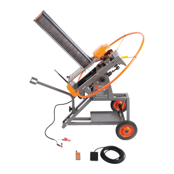
FREEDOM BIRD
AUTO-FEED TRAP
Part No. 40926
Table of
Contents
Previous
Page
Next
Page
1
2
3
4
5
Advertisement
Table of Contents
Need help?
Do you have a question about the Freedom Bird and is the answer not in the manual?
Ask a question
Questions and answers
Related Manuals for Champion Freedom Bird
Sports & Outdoors Champion High Fly 40901 Assembly And Operating Instructions Manual
Target thrower (17 pages)
Sports & Outdoors Champion SKYBIRD TRAP Owner's/Operator's Manual
(28 pages)
This manual is also suitable for:
40926
Table of Contents
Print
Rename the bookmark
Delete bookmark?
Delete from my manuals?
Login
Sign In
OR
Sign in with Facebook
Sign in with Google
Upload manual
Upload from disk
Upload from URL


Need help?
Do you have a question about the Freedom Bird and is the answer not in the manual?
Questions and answers