
Related Manuals for gefran SENSORMATE QE2008-W SET


Summary of Contents for gefran SENSORMATE QE2008-W SET
- Page 1 QE2008-W SET SYSTEM FOR STRAIN MEASUREMENT WITH BLUETOOTH TRANSMISSION, IDEAL FOR TIE BAR ANALYSIS User Manual C-0123_v1.0_ENG...
- Page 2 2 / 56 Subject to technical modifications...
-
Page 3: Table Of Contents
TABLE OF CONTENTS PREFACE ���������������������������������������������������������������������������������������������������������������������������������������������������4 Device unique data ..........................4 Warnings and safety ..........................4 Disposal ..............................4 Disclaimer ..............................4 Copyright ..............................4 WEEE INFORMATION ������������������������������������������������������������������������������������������������������������������������ ��������5 1� GENERAL DESCRIPTION ���������������������������������������������������������������������������������������������������������� ��������6 1.1. Profile ............................6 1.2. Main features ..........................6 1.3. -
Page 4: Preface
Gefran S.p.A. also reserves the right to make changes to the content and form of this document as well as the Gefran S.p.A. cannot be held in any way liable for any characteristics of the illustrated devices at any time damage to persons or property resulting from QE2008-W without prior notice. -
Page 5: Weee Information
WEEE INFORMATION „Umsetzung der Richtlinie 2012/19/EU über “Implementation of Directive 2012/19/EU on Elektro- und Elektronik-Altgeräte (EEA)“ waste electrical and electronic equipment (WEEE)” Das Symbol der durchgekreuzten Mülltonne auf dem Gerät oder der Geräteverpackung weist da- The symbol showing a crossed-out wheeled bin rauf hin, dass Sie das Produkt am Ende seines on equipment or its packaging indicates that the Lebenszyklus separat entsorgen müssen. -
Page 6: 1� General Description
1� GENERAL DESCRIPTION 1�1� Profile The double magnet wireless strain sensors QE2008-W The heart of the QE2008-W is a foil strain gauge, which are used for accurate force and strain measurements signal is enhanced by an integrated state of the art am- on ferromagnetic surfaces. -
Page 7: Qe2008-W Set
1�3�2� QE2008-W Set Example with 8 sensors� QE2008-W Set case QE2008-W USB power adapter + USB-C cable Protective foam Charging station USB-C connector 7 / 56 Subject to technical modifications... -
Page 8: Turn Qe2008-W On Or Off
1�4� Turn QE2008-W on or off Turn on • Press and hold the power button until the function LEDs turn blue. Now the device is ready for connection. If QE2008-W doesn't turn on, you might need to charge its battery. Refer to “1�6� Charging the sensors” on page Turn off • Press and hold the power button until the function LEDs turn off. -
Page 9: Sensor Operation Principles
1�7� Sensor Operation Principles The QE2008-W sensors communicate via Bluetooth 5�0 Low Energy directly with the "Sensormate" App, installed on a mobile device or a Desktop computer. The "Sensormate" app is designed to read the sensor's strain measure- ments and other parameters (e.g., the battery level, sensor orientation, firmware version, etc.) as well as to control the sensor's operation (e.g., sampling rate, signal reset, LED colors, firmware upgrade, etc.). Bluetooth 5.0 Low Energy connection established to one sensor The fundamental communication concept that regulates the behavior of the sensor is the Network. -
Page 10: 2� General Handling Requirement
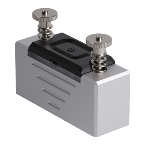
Also make sure that the package contains all accessories listed in the documentation. Warning! If even one of the above-mentioned requirements is not met, suspend installation and contact your Gefran dealer or Gefran Customer Service. 2�1� Sensor Handling and Installation... - Page 11 Knurled nuts alignement - Turn both knurled nuts so that they are flush with the end of the threaded rod. Careful placement - The long edge of the sensor must be placed onto the surface to be measured and then tilted. The magnets pull the sensor onto the surface. Placement validation - If the magnets do not auto- matically jump onto the measuring surface, press down the knurled nuts one after the other.
- Page 12 Placement optimization - The contact force can be increased by tightening the knurled nut (usually not necessary). If a magnet jumps back, the knurled nut has been tigh- tened too much, thereby making the spring tension too big. Loosen the knurled nut to relieve the tension of the spring.
-
Page 13: 3� Sensormate App
3� SENSORMATE APP Sensormate is a simple, user-friendly front end to the QE2008-W and other GEFRAN products. Its frequent updates enable constant improvement in measurement efficiency and speed, making it the best companion for sensors. 3�1� App Installation • The Sensormate app is available free of charge for Android, iOS and Windows devices. Scan the QR code or follow the link related to your device of choice to download it from the official store. -
Page 14: Scan For Qe2008-W Networks
3�2� Scan for QE2008-W Networks • When the Sensormate app is started, the device list page is presented. • A "scan for devices" is automatically launched for approximately 15s. If during this interval no QE2008-W net- works/devices were found, please make sure they are turned on and launch manually the "scan for devices". When a device has been found, it is added to the device list and becomes available for connection. -
Page 15: 4� Typical Applications
4� TYPICAL APPLICATIONS These sensors are precision instruments with a resolution of 0.1με. The devices must therefore be handled with great care. This instruction manual must be read and observed by every user. 4�1� Strain Measurement on tie bars and round surfaces 4�1�1�... - Page 16 4�1�1�1� Mounting - 2 Sensors on the Tie Bar Please refer to “2�1� Sensor Handling and Installation” on page 10 for instructions on how to install the QE2008-W sensors on any ferromagnetic surface. For this measurement, each of the 4 tie bars of the machine must have 2 QE2008-W sensors placed 180° apart from each other, at the same longitudinal position of the tie bar.
- Page 17 Incorrect! Distance not 180° Incorrect! External edges not aligned Correct! • Repeat the mounting process for the rest of the tie bars (one couple of sensors per tie bar). Before the start of your measurements, operate slowly the machine and ensure that - the sensors do not obstruct the normal operation of the machine�...
- Page 18 Navigate to the Clamping Measurement page under Applications > Clamping and tap the Mounting check button. The app will analyse the mounting of all the sen- sors. This process takes a few seconds. Once the mounting check has finished, the incor- rect mountings will be indicated with an exclamati- on mark By tapping on the tie bar name, a submenu will ...
- Page 19 While the mounting viewer is open, the function LEDs of the selected sensors will indicate their relative alignment status. LEDs are when the sensors are not correctly aligned and they are GREEN when they are correctly aligned. In case of incorrect alignment, unmount the most accessible sensor and, hovering it around the tie bar, find the position where the LEDs become GREEN.
- Page 20 4�1�1�2� Measurement procedure During the tie-bar strain measurement, the machine must not be operated or closed at high speeds as vibrations can affect the measurement� Drive the machine slowly� After the sensors have been mounted and their mounting position has been checked with the Sensormate app, perform 3 dry cycles (without injection), only closing and opening the press.
- Page 21 Close the press. The sensors will continue sending the measured strain to the app durign the whole process. Check if the Unbalance indicator and one tie bar are highlighted in blue. A highlighted tie bar indicates that the tie bar strain value is out of the set tolerance.
- Page 22 10. Open the press. 11. Hit the Play play_arr button to start logging the data in the graph. 12. Close the press. The curve of measurements can be seen on the chart. pause 13. Stop the logging of data with the Pause button.
- Page 23 • When strain is selected as "unit", the average of all the Tie Bar strain values is shown below the “Aver- age” title. • When instead one of the available forces is selected as "unit", the sum of all the Tie Bar force values is shown under the “Total”...
- Page 24 Clamping Chart Page • To log measurements in real time, select the page Clamping Chart arrow_fo Sensormate graphing and analysis tool is shown. • In the upper left corner the control panel is shown. • In the lower left corner the legends are shown. tune • Tapping folds or expands the control panel.
- Page 25 • When a curve is highlighted, the individual values of the curve can be displayed by simply tapping, holding and swiping across the graph while keeping holded (hovering the cursor over the graph on Desktops). swipe touch_ap • Curves can be hidden individually by long-pressing their legend (right-click on Desktops).
-
Page 26: Bending Analysis
4�1�2� Bending analysis When a circular beam bends, tension and compression are produced inside the beam. Some parts of the beam are pushed together, while some others are stretched. The following image shows an overlay of a bent beam on top of the original, straight beam. The bottom surface of the beam gets longer in length, while the top surface of the beam gets shorter in length. - Page 27 4�1�2�1� Mounting - 4 Sensors on the Tie Bar Please refer to “2�1� Sensor Handling and Installation” on page 10 for instructions on how to install the QE2008-W sensors on any ferromagnetic surface. For this measurement, 4 sensors must be placed on a single tie bar. The sensors must be evenly distributed around the tie bar, 90°...
- Page 28 Incorrect! Distance not 180° Incorrect! External edges not aligned Correct! • Grab a third sensor and mount it on the same tie bar at 90° from the other two already mounted sensors, aligning the external edges with the other sensors. • Finally, mount the last sensor at 180°...
- Page 29 - The sensors must be positioned parallel to the tie bar! - All the sensors must be evenly distributed around the tie bar 90° apart from each other and at the same position! - Mount the sensors when there is no load applied (e�g� no force applied on the object / mold open) By operating the machine in a slow and controlled manner, ensure that - the sensors do not obstruct the normal operation of the machine�...
- Page 30 swipe touch_ap The relative position of the sensors in the bending page must be identical to the physical layout of the sensors mounted on the tie bar� Once the desired sensors are selected, tap the Mounting check button. The mounting tool appears: the sensors highlighted GREEN are correctly placed on the tie bar, while the ones highlighted in...
- Page 31 While the mounting viewer is open, the function LEDs of the selected sensors will indicate their relative alignment status. LEDs are when the sensors are not correctly aligned and they are GREEN when they are correctly aligned. In case of incorrect alignment, unmount the non-correctly aligned sensor and, hovering it around the tie bar, find the position where the LEDs become GREEN.
- Page 32 4�1�2�2� Measurement procedure During the tie-bar strain measurement, the machine must not be operated or closed at high speeds as vibrations can affect the measurement� Drive the machine slowly� After the sensors have been mounted and their mounting position has been checked with the Sensormate app, perform 3 dry cycles (without injection), only closing and opening the press.
- Page 33 For a detailed explanation on the Bending Measure- ment page, please refer to the sections “4�1�2�3� Pages details” on page 34� Press the RESET button. This will remove the resi- dual values the sensors may have (Tare). touch_ap Close the press. The Maximum Tension applied on the tie bar as well as the Bending Direction are measured and presented.
- Page 34 4�1�2�3� Pages details Bending Measurement Page • A cross-section of a tie bar with 4 QE2008-W sensors is presented. The sensors are located around the tie bar in steps of 90°, in accordance with the physical mounting of the sensors. • By default, sensors 1.1, 1.2, 2.1 and 2.2 are selected for the bending measurement.
- Page 35 • The maximum tension applied on the tie bar's surface is located below the Max� Tension title. This value can be displayed in the strain unit "με" (micro strain) as well as in the force units "kN" (kilo Newton), “t” (tons), "tUS"...
- Page 36 Example Bending axis Maximum tension Exaggerated bending representation 36 / 56 Subject to technical modifications...
-
Page 37: Cavity Pressure Profile - Fast Acquisition Measurement
4�1�3� Cavity Pressure Profile - Fast acquisition measurement In the plastic injection molding process, molten plastic at high temperatures is injected under pressure into a mold cavity, where it fills the mold and solidifies to create the final product. This is a cyclic process that consists of four phases: filling, melt compressing (or packing), holding, and cooling, each with a series of adjustable parameters that determine the efficiency of the process and the quality of the final product. A given configuration that produces a high quality final part will most likely not have the same result when producing a different part with different characteristics. The optimal parameters for achieving a high quality product with high efficiency depend directly on the mold used, the type of plastic, the machine, and many other aspects. Discovering all these ideal parameters often involves a series of time-consuming trial-and-error iterations that do not guarantee to find the perfect combination. - Page 38 4�1�3�1� Measurement prerequisites The Cavity Pressure Profile measurement using the QE2008-W is an indirect measurement of the pressure on the press' Tie Bars. The basic physics concept that lies behind the measurement is that a pressure (P), when applied to a surface (A), generates a force (F).
- Page 39 4�1�3�2� Sensor mounting Please refer to “2�1� Sensor Handling and Installation” on page 10 for instructions on how to mount the QE2008-W sensors on any ferromagnetic surface. For this measurement, it is enough that only one sensor is mounted on only one tie bar, and it's not mandatory that each of the 4 tie bars of the machine have 2 QE2008-W sensors mounted.
- Page 40 4�1�3�3� Measurement procedure During the tie-bar strain measurement, the machine must not be operated or closed at high speeds as vibrations can affect the measurement� Drive the machine slowly� After the sensors have been mounted, perform 3 dry cycles (without injection), only closing and opening the press.
- Page 41 arrow_fo Press the Start button to launch the high rate sampling. In the same moment, start the injection process on the Injection Molding or Die Casting machine. The interaction with the app is blocked until the pro- cess is finished. In the meantime, the app will pre- sent a preview of the measurements in the graph which was acquired with normal sampling rate.
- Page 42 10. Analyse the differences, if any, and consult the relevant literature in order to determine the reason for the poorly achieved curve. 11. If needed, save the measurement for tracking pur- save_alt poses with the Save button. 12. Implement the necessary corrections on the machi- ne setup and measure again.
- Page 43 4�1�3�4� Pages details Cavity Pressure Chart Page • To log measurements in real time, select the page Cavity Pressure Chart arrow_fo Sensormate graphing and analysis tool is shown. • In the upper left corner the control panel is shown. • In the lower left corner the legends are shown.
- Page 44 • When a curve is highlighted, the individual values of the curve can be displayed by simply tapping, holding and swiping across the graph while keeping holded (hovering the cursor over the graph on Desktops). swipe touch_ap • Curves can be hidden individually by long-pressing their legend (right-click on Desktops).
-
Page 45: 5� Network Configuration
5� NETWORK CONFIGURATION As explained in “1�7� Sensor Operation Principles” on page 9, the "Sensormate" app can connect to several devices at the same time when they belong to the same network. By default, sensors are already assigned to a net- work and they are ready to use. - Page 46 Connect to the sensor to be removed from the network. Hit the Remove from Network button under the Settings page. touch_ap A pop-up message will confirm that the removal was successful, and the app will disconnect from the sensor. Now the sensor doesn't belong to any network, and it has become an unassigned sen- sor.
-
Page 47: Adding A Qe2008-W Sensor To A Network
5�2� Adding a QE2008-W sensor to a network Folow these steps to add an unassigned QE2008-W sensor to an existing QE2008-W network. In the following example, an unassigned sensor is added to the network with ID 42CA000531 at position 1�1. If the Sensormate app has an active connection, disconnect. - Page 48 The app will now establish a connection with an unassigned device. If the Sensormate application discovered more than one unassigned device, a pop-up message will ask the user to select the unassigned sensor they wish to add to the network. If wanted, press the Loop button to search for ano- ther sensor, then press Select.
-
Page 49: Creating A New Network
5�3� Creating a new network Folow these steps to create a new QE2008-W network. In the following example, a new network with the ID "NewNetwork" will be created. Note that an unassigned sensor is required to create new networks. If needed, follow the section “5�1� Removing a QE2008-W sensor from a net- work”... - Page 50 f the Sensormate application discovered more than one unassigned device, a pop-up message will ask the user to select the unassigned sensor they wish to add to the new network. If wanted, press the Loop button to search for ano- ther sensor, then press Select.
-
Page 51: 6� Firmware Upgrade
Update Firmware button on the About page will become enabled. Once pressed, all the outdated sensors within the network will be automatically updated. Note that an active internet connection is necessary in order to check the availability of new firmware versions on the Gefran database. The update of the firmware of a single sensor can take up to 1.5 minutes. Updating a set of 8 sensors can last up to 10 minutes. We recommend to perform this step while the sensors are sitting in the charging case and charging is ongoing. -
Page 52: 7� Technical Specifications
7� TECHNICAL SPECIFICATIONS 7�1� QE2008-W SET TECHNICAL DATA SENSOR On board power supply Integrated LiPo battery 3.7V 330mAh Charging specification 5V, 175mA TECHNICAL DATA WIRELESS PROTOCOL Frequency 2.4000-2.4835 GHz (ISM-Band) Protocol transceiver to end device Bluetooth 5 (Low Energy) End device compatibility Sensormate App: - Windows 10 or newer - Android 6.0 or newer... - Page 53 JAPAN - MIC The used module comply with the Japanese Technical Regulation Conformity Certification of Specified Ra- dio Equipment (ordinance of MPT N°. 37, 1981), Article 2, Paragraph 1: - Item 19 „2.4 GHz band wide band low power data communication system TAIWAN – NCC • Without permission granted by the NCC, any company, enterprise, or user is not allowed to change frequency, enhance transmitting power or alter original characteristic as well as performance to an approved low power radio-frequency devices.
-
Page 54: 8� Troubleshooting
The QE2008-W sensors should be calibrated every 12 months to assure the measurement metrical parameters and stability. This process can be executed only by professionally trained staff in Sensormate AG. Contact your Gefran dealer or Gefran Customer Service to organize this task. - Page 55 Notes and citations: [1] Tie-Bar Elongation Based Filling-To-Packing Switchover Control and Prediction of Injection Molding Quality - Ji- an-Yu Chen, Chun-Ying Liu and Ming-Shyan Huang [2019] 55 / 56 Subject to technical modifications...
- Page 56 SENSORMATE AG Steigweg 8 Tel. +41 (0)52 523 25 00 info@sensormate.ch CH-8355 Aadorf Fax +41 (0)52 364 32 72 www.sensormate.ch Schweiz...
Need help?
Do you have a question about the SENSORMATE QE2008-W SET and is the answer not in the manual?
Questions and answers