
Related Manuals for gefran 650 L


Summary of Contents for gefran 650 L
- Page 1 650 L - 1250 L Alarm limit indicator INSTALLATION AND INSTRUCTION MANUAL code: 80224A...
-
Page 3: Table Of Contents
1.3. Indicator 650 L ...............8 4.4.6. xxxxx - Model of indicator ............35 1.3.1. Display and keys 650 L ............8 4.4.7. INDIC - Type of indicator ............35 1.3.2. Cutout and mounting dimensions ..........9 4.4.8. OUT.A1 - Analog output 1 available ........35 1.4. - Page 4 4.11.3. PAr - Selecting parity ............60 Order methods ............4.12. HMI Submenu – Configuring the display and keypad ..61 10.1. 650 L model list ..............85 4.12.1. bArG - Selecting the bargraph display .........62 4.12.2. MSG.LO - -Lo message display ...........62 10.2.
-
Page 5: Introduction
Device data This information will be needed by Gefran Customer Service in order to provide technical assistance. In the space below, write the order code and other plate data shown on the label attached to the outside of instrument (see figure). -
Page 6: Symbols Used In This Manual
MUST be followed. Indicates a reference to other technical documents Indicates risk for the safety of the installer or user that can be downloaded from www.gefran.com. due to the presence of high voltage. Indicates a point to which the reader’s attention is called. -
Page 7: Disclaimer
They may be the result of test conditions at Gefran S.p.A., and the user must compare them to his/her real application Gefran S.p.A. also reserves the right to change the contents requirements. -
Page 8: General Description
1.1. Profile 650 L 1250 L Indicators 650 L and 1250 L are a family of devices used to Initial commissioning is simplified by guided configuration limit overheating in industrial processes. text prompts that cover the commonly used base parameters accompanied by in line help messages. -
Page 9: Differences Between Models
1. GENERAL DESCRIPTION 1.2. Differences between models 650 L 1250 L Display dimensions 35 × 30 mm (1.38” x 1.18”) 37 × 68 mm (1.46” x 2.68”) PV display 4 digit, 7 seg., H = 17 mm (0.67”) 4 digit, 7 seg., H = 17 mm (0.67”) SV display 5 digit, 14 seg., H = 7 mm (0.27”) -
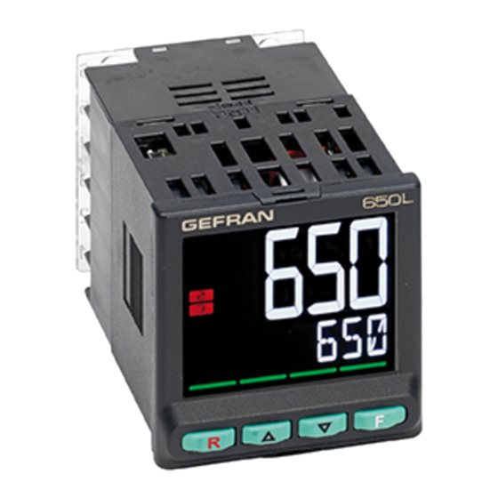
Page 10: Indicator 650 L
It can be used to view the alarm limit and displays the associated message in the event of alarm. PV display: process variable, parameter values. Figure 1 - Description of 650 L display and keys 80224_MHW_650 L - 1250 L_07-2018_ENG - 8... -
Page 11: Cutout And Mounting Dimensions
1. GENERAL DESCRIPTION 1.3.2. Cutout and mounting dimensions 2.76 2.28 1.89 +0.6 - 0.0 1.78 Figure 2 - 650 L Cutout and mounting Dimensions 80224_MHW_650 L - 1250 L_07-2018_ENG - 9... -
Page 12: Indicator 1250 L
1. GENERAL DESCRIPTION 1.4. Indicator 1250 L Main features • Operator interface with large LCD Display, customi- zable, with choice of colors • Scrolling diagnostic messages, configurable, in the se- lected language • Easy, guided configuration, copy/paste parameters even with power off •... -
Page 13: Cutout And Mounting Dimensions
1. GENERAL DESCRIPTION 1.4.2. Cutout and mounting Dimensions 1.89 2.76 + 0.6 - 0.0 1.78 Figure 4 - 1250 L Cutout and mounting Dimensions 80224_MHW_650 L - 1250 L_07-2018_ENG - 11... -
Page 14: Installation
(“Figure 2 - 650 L Cutout and mounting protect the exposed terminals on the rear of the instrument. -
Page 15: Vibrations
Attention! Forced cooling (for example, with a fan) of the rear of the instrument may cause measure- ment errors. Figure 6 - Fastening the 650 L 2.1.6. Positioning The indicator must be positioned so that the display is not subject to direct sunlight or to very strong sources of light. -
Page 16: Connections
2. INSTALLATION 2.2. Connections Attention! Failure to follow the instructions in this Cable / terminal Cable / terminal Terminal size section may cause problems in electrical safety and section electromagnetic compatibility, in addition to voiding 0,2...2,5 mm Rigid cable the warranty. (24...14 AWG) 0,2...2,5 mm 2.2.1. -
Page 17: Connecting Inputs And Outputs
2. INSTALLATION Attention! If the instrument is connected to devi- 2.2.5. Connecting inputs and outputs ces that are NOT electrically isolated (such as ther- mocouples), ground with a separate conductor to prevent grounding directly through the machine To prevent noise, the instrument’s input and output wiring structure. -
Page 18: Connection Diagrams
2. INSTALLATION 2.3. 650 L connection diagrams 2.3.1. General diagram OUT 2 OUT 1 5 V, 10 V OUT 3 OPTIONS IN 1 B (Data +) A (Data -) LEGEND dry contact digital input Relay output Thermocouple input Isolated analog output... -
Page 19: Power Supply
2. INSTALLATION 2.3.2. Power supply Input PT100/JPT100 - 3-wires connection Powe supply Attention: with this type of connection the line resi- stance can introduce measurement error, we recommend that you use wires of ade- Standard: 100...240VAC/VDC ± 10% quate cross-section. 50/60Hz, max 5 VA The resistance of the three wires must be equal, and less than 20 ohm. -
Page 20: Options
2. INSTALLATION 2.3.5. Options Types of optional inputs and outputs are specified when is ordered. Option Analog output 0...10 V, I 20 mA Out A1 0...20 mA, 4...20 mA R < 500 Ω Digital inputs dry contact B (Data +) Serial line RS485 2-wires A (Data -) -
Page 21: 1250 L Connection Diagrams
2. INSTALLATION 2.4. 1250 L connection diagrams 2.4.1. General diagram OUT 3 IN 5 OUT 2 IN 4 IN 3 OUT 1 IN 2 IN 1 5 V, 10 V B (Data +) A (Data -) LEGEND dry contact digital inputs Relay output Thermocouple... -
Page 22: Power Supply
2. INSTALLATION 2.4.2. Power supply Input PT100/JPT100 - 3-wires connection Powe supply Standard: 100...240VAC/DC ± 10% Attention: 50/60Hz, max 10VA with this type of connection the line resi- stance can introduce measurement error, we recommend that you use wires of ade- Optional: 20...27VAC/DC ±... -
Page 23: Digital Inputs
2. INSTALLATION 2.4.5. Digital inputs 2.4.7. Analog output Digital inputs Analog output Analog output Digital inputs 0...10 V, max 20 mA dry contact Out A1 0...20 mA, 4...20 mA, Rout < 500Ω Digital inputs Digital inputs NPN 24 V, 4,5 mA Digital inputs PNP digital inputs +12/24 V max 3,6 mA... -
Page 24: Rs485 Serial Connection Diagram
(120 Ω, 1/2 W). Host computer RS485 Shield Earth ground (FG) No. 1 No. 31 1/2 W Figure 10 - RS485 connection for 650 L indicators Host computer RS485 Shield Earth ground (FG) 1/2 W 1250 1250 No. 1 No. -
Page 25: Commissioning
Displays The general description of the displays and keys for each model is in paragraphs “1.3.1. Display and keys 650 L” on The indicators have 2 or 3 displays, depending on the model. page 8, “1.4.1. Display and keys 1250 L” on page 10. -
Page 26: Power-On Sequence
3. COMMISSIONING 3.1.2.2. Scrolling messages “ & ‘ The SV (650 L) and F (1250 L) displays can show scrolling alphanumeric messages. These messages, up to 32 cha- racters in length, appear: • during configuration, describing the active parameter; •... -
Page 27: First Power-On
3. COMMISSIONING 3.3. First power-on At first power-on, after the indicator has run the self-diagnostics test, press the key to access the Fast Configuration Menu. The parameters shown are a subset of all the indicator parameters and let you rapidly configure the inputs and outputs. - Page 28 3. COMMISSIONING Home Select output 2 function The allowed functions depend on output type (relay, logic). > 2 s Select output 3 function The menu item appears only if the optional output is available. > 2 s 80224_MHW_650 L - 1250 L_07-2018_ENG - 26...
- Page 29 3. COMMISSIONING Home Select digital input 1 function The menu item appears only if the optional input is available. > 2 s Select digital input 2 function The menu item appears only if the optional input is available (for model 1250 L). >...
- Page 30 3. COMMISSIONING Home Select digital input 5 function The menu item appears only if the optional input is available (for model 1250 L). > 2 s Raises the value Setting Alarm 1 Lowers the value > 2 s Raises the value Setting Modbus address The menu item appears only if the optional RS485 port is available.
-
Page 31: Setting Up Quick Configuration
3. COMMISSIONING 3.4. Setting up quick configuration The quick configuration menu lets you quickly configure ration menu (see paragraph “4.1. Programming/Configura- and start an indicator. tion Menu” on page 30), which gives access to all of the parameters. To do this, it uses default values for many of the parameters assigned to the functions. -
Page 32: Configuration
- if the entered value does not match that expected, the Home screen will be displayed In case of doubts, or if you need any explanations, please consult www.gefran.com or contact Gefran Customer Care. 4.1.2. Passwords The configuration menu is protected by 2 passwords that allow access to two different menu sections. -
Page 33: Main Menu
4. CONFIGURATION 4.2. Main menu > 6 s Home 0000 Submenu Submenu page page 0000 > 2 s Insert password 1 Insert password 2 PASS1 PASS2 User configuration menu If password is correct, enter menu, If password is correct, enter menu, (max 50 parameters) if not, Home if not, Home... -
Page 34: Legend For Submenus And Parameters
4. CONFIGURATION 4.3. Legend for submenus and parameters The purposes and characteristics of submenus and parameters are described and summarized in the following tables. 4.3.1. Submenu Acronym Scrolling message Password Description INFO INSTRUMENT STATUS Level 1 Gives information on indicator state and HW configuration Acronym of submenu as it appears on indicator di- splay. -
Page 35: Info Submenu - Information Display
4. CONFIGURATION 4.4. INFO Submenu - information display Acronym Scrolling message Password Description INFO INSTRUMENT STATUS Level 1 Gives information on indicator state and HW configuration. Parameter Page Parameter Page Parameter Page Software version SW.VER Identifying Digital input Number of 1.IN.DG CODE code of indicator... -
Page 36: Sw.ver - Software Version
4. CONFIGURATION 4.4.1. SW.VER - Software Version Acronym Scrolling message Password Description SW.VER SOFTWARE VERSION INFO The parameter shows the version (major.minor) of the indicator software. Unit of measurement: - Options: 4.4.2. CODE - Serial address of the indicator Acronym Scrolling message Password Description... -
Page 37: Model Of Indicator
If present, the parameter indicates how many digital inputs are installed on the indicator. Unit of measurement: Options: 1.IN.DG = 1 digital input installed on the indicator (for 650 L only) 5.IN.DG = 4 digital input installed on the indicator (for 1250 L only) 4.4.10. RS485 - RS485 serial port available... -
Page 38: Out1 - Type Of Output
4. CONFIGURATION 4.4.11. Out1 - Type of output Acronym Scrolling message Submenu Attributes Out1 OUTPUT TYPE INFO The parameter specifies the type of output 1. Unit of measurement: Options: RELAY = Relay output 4.4.12. Out2 - Type of output Acronym Scrolling message Submenu Attributes... -
Page 39: Out3.S - Number Of Cycles Output 3
4. CONFIGURATION 4.4.16. OUT3.S - Number of cycles output 3 Acronym Scrolling message Submenu Attributes OUT3.S NUMBER X 1000 RELAY CYCLES INFO If output 3 is available on the indicator, the parameter shows the number of cycles (in thousands). Unit of measurement: Number (×... -
Page 40: T.max - Maximum Internal Temperature Of The Indicator
4. CONFIGURATION 4.4.21. T.MAX - Maximum internal temperature of the indicator Acronym Scrolling message Submenu Attributes T.MAX MAX INTERNAL TEMPERATURE INFO The parameter shows the maximum internal temperature of the indicator. Unit of measurement: °C Options: 80224_MHW_650 L - 1250 L_07-2018_ENG - 38... -
Page 41: I.main Submenu - Configuration Of Main Input
4. CONFIGURATION 4.5. I.MAIN Submenu - Configuration of main input Acronym Scrolling message Password Description I.MAIN MAIN INPUT CONFIG Level 1 Lets you configure the indicator’s main input. Upper limit for setpoint Parameter Parameter page page tyPE Selecting Lower limit for alarms LO.AL sensor type SBR.E... -
Page 42: Type - Selecting Sensor Type
4. CONFIGURATION 4.5.1. tyPE - Selecting sensor type Acronym Scrolling message Submenu Attributes tyPE MAIN INPUT TYPE OF PROBE I.MAIN The parameter shows and sets the sensor type of the main input. The functions for calibrating Custom sensors are on the US.CAL menu. When a 4...20 mA input is used and the current is less than 2 mA, an Err message is generated and the relay state speci- fied with the FAUL.T parameters is activated. -
Page 43: Sbr.e - Enabling Sensor Break Alarm (Sbr)
4. CONFIGURATION Unit of measurement: Options: J.TC = J thermocouple K.TC = K thermocouple R TC = R thermocouple S TC = S thermocouple T.TC = T thermocouple C.TC = C thermocouple D.TC = D thermocouple B.TC = B thermocouple E.TC = E thermocouple L.TC... -
Page 44: Lin - Linearization Type
4. CONFIGURATION 4.5.3. Lin - Linearization type Acronym Scrolling message Submenu Attributes CUSTOM LINEARIZATION I.MAIN The parameter sets linearization for the selected sensor type. The function corrects any linearity and proportionality errors in the correlation between measured value and the actual value. -
Page 45: Filt.d - Digital Filter On Pv Display
4. CONFIGURATION 4.5.6. FILT.D - Digital filter on PV display Acronym Scrolling message Submenu Attributes FILT.D DIGITAL FILTER ON DISPLAY PV I.MAIN The parameter shows and sets the allowed tolerance between the real PV value and the value on the PV display: if the variation in real PV is within the interval displayed value - FILT.D... -
Page 46: Hi.scl - Upper Limit Of Scale
4. CONFIGURATION 4.5.9. HI.SCL - Upper limit of scale Acronym Scrolling message Submenu Attributes HI.SCL INPUT HIGH LIMIT I.MAIN The parameter shows and sets the upper limit of the measurement scale used for the main input, based on input (or sen- sor) type, engineering units, and number of decimals selected. -
Page 47: Alarm Submenu - Configuration Of Alarms
4. CONFIGURATION 4.6. ALARM Submenu - Configuration of alarms Acronym Scrolling message Password Description ALARM ALARM CONFIG Level 1 Lets you configure the generic alarms. Parameter Parametro page pag. Selecting the alarm Message associated ALARM to be configured MSG.AL with tripping of alarm Message associated with d.i.x Selecting direct or... -
Page 48: Alarm - Selecting The Alarm To Be Configured
4. CONFIGURATION 4.6.1. ALARM - Selecting the alarm to be configured Acronym Scrolling message Submenu Attributes ALARM ALARM NUMBER ALARM The parameter shows and sets the alarm to be configured, identified by its number. Unit of measurement: Number Options: 1...ALRM.N = Identifying number of alarm, where ALRM.N is the total number of alarms, setting by submenu MODE. -
Page 49: Pwon.e - Disabling The Alarm At Power-On
4. CONFIGURATION 4.6.5. PWON.E - Disabling the alarm at power-on Acronym Scrolling message Submenu Attributes PWON.E DISABLE AT SWITCH ON ALARM The parameter shows and sets the behavior of the alarm (being configured) when the indicator is powered on. If the parameter is “OFF,” the alarm will trip when the indicator is powered on if the process variable exceeds the alarm setpoint limits. -
Page 50: Delay - Alarm Trip Delay
4. CONFIGURATION The parameter shows and sets the alarm trip delay for the alarm being configured, i.e., the time that the value of the process variable has to exceed the alarm setpoint for the alarm to trip. This parameter prevents repeated alarms due to instantaneous and insignificant exceeding of that value or nuisance trips. If the parameter is set to “0.00”... -
Page 51: Blk.al - Flashing Of Pv Display
4. CONFIGURATION 4.6.11. BLK.AL - Flashing of PV display Acronym Scrolling message Submenu Attributes BLK.AL BLINK DISPLAY PV DEF ALARM The parameter shows and sets the flashing of the PV display in case of alarm, for the alarm being configured. If the parameter is “On,”... -
Page 52: I.digt Submenu - Configuring Digital Inputs
4. CONFIGURATION 4.7. I.DIGT Submenu – Configuring digital inputs Acronym Scrolling message Password Description I.DIGT DIGITAL INPUT CONFIG Level 2 Lets you configure the indicator’s digital inputs. The menu is present if there are digital inputs. Parameter page Selecting the I.DIG.N digital input S.in.x... -
Page 53: I.dig.n - Selecting The Digital Input
4. CONFIGURATION 4.7.1. I.DIG.N - Selecting the digital input Acronym Scrolling message Submenu Attributes I.DIG.N DIGITAL INPUT NUMBER I.DIGT The parameter shows and sets the identifying number of the digital input to be configured. Unit of measurement: Number Options: 1...5 for model 1250 L with 5 digital inputs option 4.7.2. -
Page 54: Outpu Submenu - Configuring Outputs
4. CONFIGURATION 4.8. OUTPU Submenu – Configuring outputs Acronym Scrolling message Password Description OUTPU OUTPUT CONFIG Level 2 Lets you configure the indicator outputs. Parameter page Selecting the output OUT.N S.ou.x Defining the output state Selecting the F.ou.x function assigned to relay Setting the digital IN.DGN... -
Page 55: Out.n - Selecting The Output
4. CONFIGURATION 4.8.1. OUT.N - Selecting the output Acronym Scrolling message Submenu Attributes OUT.N OUTPUT NUMBER OUTPU The parameter shows and sets the identifying number of the output to be configured. Unit of measurement: Number Options: 1...3 4.8.2. S.ou.x - Defining the output state Acronym Scrolling message Submenu... -
Page 56: Swtch - Output Cycle Limit Alarm
4. CONFIGURATION 4.8.5. SWTCH - Output cycle limit alarm Acronym Scrolling message Submenu Attributes SWTCH NUMBER OF SWITCHING CYCLES OUTPU The parameter shows and sets the number of cycles (x1000) of the relay, exceeding which the signal is generated OUTX. SWITCH ALARM where X is the number of output 1 or 2 or 3 or 4 if the output is relay, logic or triac. -
Page 57: Out.an - Submenu - Configuring The Analog Retransmission Output
4. CONFIGURATION 4.9. OUT.AN - Submenu – Configuring the analog retransmission output Acronym Scrolling message Password Description OUT.AN ANALOG Level 2 Lets you configure the analog output used for retransmission RETRASMISSION of analog values. OUTPUT CONFIG The submenu appears if the analog retransmission output is present on the indicator. -
Page 58: S.o.a1 - Defining The Signal Direction Of The Analog Output
4. CONFIGURATION 4.9.1. S.o.A1 - Defining the signal direction of the analog output Acronym Scrolling message Submenu Attributes S.o.A1 ANALOG OUTPUT STATUS OUT.AN The parameter shows and sets the state of analog retransmission output A1. The active direct output corresponds to minimum with the minimum output value in voltage or current. The active inverse output corresponds to minimum with the maximum output value in voltage or current. -
Page 59: Mode Submenu - Functionality Configuration
4. CONFIGURATION 4.10. MODE Submenu – Functionality configuration Acronym Scrolling message Password Description MODE FUNCTION MODE Level 2 Lets you configure the indicator’s functioning mode. MANAGER Parameter page Defining type of digital inputs Number of alarms ALRM.N enabled Base time settings for ALARM1 alarm condition tY.tM persistence... -
Page 60: Dig - Defining Type Of Digital Inputs
4. CONFIGURATION 4.10.1. dIG - Defining type of digital inputs Acronym Scrolling message Submenu Attributes DIGITAL INPUT TYPE MODE The parameter shows and sets the type of digital inputs. Unit of measurement: Options: = NPN digital inputs or dry contact = PNP digital inputs 4.10.2. -
Page 61: Seria Submenu - Configuring Serial Communication
4. CONFIGURATION 4.11. SERIA Submenu – Configuring serial communication Acronym Scrolling message Password Description SERIA SERIAL Level 2 Lets you configure serial communication COMMUNICATION CONFIG Parameter page Identification code CODE Selecting KBAUD communication speed Selecting parity 80224_MHW_650 L - 1250 L_07-2018_ENG - 59... -
Page 62: Code - Identification Code
4. CONFIGURATION 4.11.1. CODE - Identification code Acronym Scrolling message Submenu Attributes CODE INSTRUMENT ID CODE FOR SERIAL COMM SERIA The parameter shows and sets the identifying address of the indicator in a Modbus serial network. Generally should not be set to “1” Unit of measurement: Number Options:... -
Page 63: Hmi Submenu - Configuring The Display And Keypad
4. CONFIGURATION 4.12. HMI Submenu – Configuring the display and keypad Acronym Scrolling message Password Description DISPLAY AND Level 2 Lets you configure the indicator’s display and keys KEYBOARD Parameter Parameter page page bArG Selecting the Selecting the message MSG.SB bargraph display assigned to Sbr Selecting the... -
Page 64: Barg - Selecting The Bargraph Display
4. CONFIGURATION 4.12.1. bArG - Selecting the bargraph display Acronym Scrolling message Submenu Attributes bArG BARGRAPH FUNCTION The parameter displays and sets the view associated with the bar graph. The parameter only appears if the indicator is 1250 L. Unit of measurement: Options: NONE = No indication (bar graph off) -
Page 65: Msg.er - Err Message Display
4. CONFIGURATION 4.12.4. MSG.ER - Err message display Acronym Scrolling message Submenu Attributes MSG.ER NUM SCROLLING MSG WHEN MAIN INPUT IS ERR ERR The parameter shows and sets the number of the message assigned to Err (Pt100 in short circuit or input values below minimum limit), i.e., the scrolling message shown on the display. -
Page 66: Backl - Backlighting Level
4. CONFIGURATION 4.12.8. BACKL - Backlighting level Acronym Scrolling message Submenu Attributes BACKL BACKLIGHT LEVEL The parameter shows and sets the backlight level on the display (when the indicator is on) 10 seconds after the last key has been pressed. With “0,”... -
Page 67: Linrz Submenu - Configuring Custom Linearization
4. CONFIGURATION 4.13. LINRZ Submenu – Configuring custom linearization Acronym Scrolling message Password Description LINRZ CUSTOM Level 2 Lets you configure the parameters for custom linearization in LINEARIZATION CONFIG 32 steps or 4 points. The submenu is visible only if custom linearization was enabled in the configuration of the main input or of the setpoint input. -
Page 68: Stp.xx - Value Of Step Xx
4. CONFIGURATION 4.13.1. STP.xx - Value of step xx Acronym Scrolling message Submenu Attributes STP.xx CUSTOM LINEARIZATION STEP LINRZ The parameter shows and sets the value of the various steps, with xx from 0 to 32. The low scale value goes in STP.00 and the full-scale value in STP.32. The value of the nth step corresponds to the input: mV start scale + n*ΔmV con ΔmV = (mV full scale - mV start scale)/32. -
Page 69: Cal Submenu - User Calibrations
4. CONFIGURATION 4.14. US.CAL Submenu – User calibrations Acronym Scrolling message Password Description US.CAL USER CALIBRATION Level 2 Lets the user calibrate the indicator with regard to Custom MANAGER main input, HB alarm setpoints, energy reset, and partial day count. Parameter page U.CAL... -
Page 70: U.cal - Selecting The User Calibration
4. CONFIGURATION 4.14.1. U.CAL - Selecting the user calibration Acronym Scrolling message Submenu Attributes U.CAL USER CALIBRATION TYPE US.CAL The parameter shows and sets the parameter, input or output to which calibration will be applied. Unit of measurement: Options: NONE = No calibration P.DAYS = Reset partial day count I.MAIN = Calibration of custom main input (selected with parameter tyPE on I.MAIN menu) -
Page 71: Rtd.lo - Calibrating Minimum Resistance Value
4. CONFIGURATION 4.14.5. RTD.LO - Calibrating minimum resistance value Acronym Scrolling message Submenu Attributes RTD.LO US.CAL The parameter appears if you are calibrating a custom I.MAIN RTD input. To calibrate: • apply a resistance corresponding to minimum scale value to the main input (for example, 18.52 Ω for Pt100 ; •... -
Page 72: Pasc0 - Setting Level 0 Password
4. CONFIGURATION 4.15. PASC0 – Setting level 0 password Acronym Scrolling message Submenu Attributes PASC0 SET PASS0 Level 2 The parameter is used to set the password to access User Menu parameters. Default code = 10 Unit of measurement: Number Options: 0...9999 4.16. -
Page 73: Examples And Application Notes
(°C); ple indicators. • the temperature value that trips the alarm (ALRM1). The diagram below shows the various connections. 5.1.1. Connection diagram indicators Fuse relay alarm fuse Snubber Cooling alarm 650 L 80224_MHW_650 L - 1250 L_07-2018_ENG - 71... -
Page 74: Quick Configuration Procedure For Model 650L - R-Rr0-00000-1-G
5. EXAMPLES AND APPLICATION NOTES 5.1.2. Quick configuration procedure for model 650L - R-RR0-00000-1-G Home Selecting sensor type Selecting unit of measurement The engineering units can be °C or °F only if a TC or Rtd sensor is selected > 2 s Select output 2 function The functions proposed are based on type of logic output. -
Page 75: 4-Point Input Correction
5. EXAMPLES AND APPLICATION NOTES 5.2. 4-point input correction The 4-point input correction lets you correct the reading of The reference points on the real curve (input) are: the main input and/or of the remote setpoint input by setting • A1 = STP.00 = 50, four values: A1, B1, A2 and B2. -
Page 76: Alarms
5. EXAMPLES AND APPLICATION NOTES 5.3. Alarms 5.3.1. Generic alarms AL2-4 Note: AL1 is latched and only used for high limit control. Reset is required Normal absolute alarm Symmetrical absolute alarm AL2 +[H2] AL3+H3 AL2+H2 AL2 - [H2] time time Alarm 2 inverse Alarm 3... -
Page 77: Programming With Pc
Attention! To use this interface you have to install the VCP driver, downloadable from: www.gefran.com/en/products/261-gf_express When the indicator is connected to the PC you can confi- gure it without applying power. The instrument configuration memory is powered by the USB connection. -
Page 78: Operator Guide
The display and keys for each model are described in para- Each time the key is pressed, you go back to the graphs “1.3.1. Display and keys 650 L” on page 8 for the previous menu item or to the higher menu level, ac- 650 L, “1.4.1. -
Page 79: Errors During Operation
If provided during configuration of the indicator, a specific meter HI.SCL on I.MAIN). scrolling message appears on the SV display (model 650 L) PT100 in short circuit or input values below minimum or on the F display (model 1250 L). -
Page 80: Configuration (User Menu)
7. OPERATOR GUIDE 7.5. Configuration (User menu) Every operator has a freely accessible menu (no password The indicator leaves the factory with a preconfigured user required) on which he can configure indicator parameters. configuration menu (shown below for models 650L-x-xxx- 00000-x-xxx and 1250L-x-xxx-00000-x-xxx). - Page 81 7. OPERATOR GUIDE Description/ Unit of Valid values Note Scrolling message measurement Alarm 1 limit scale points LO.AL...HI.AL Read-only value ALRM1 ALARM SETPOINT Read-only valuey Alarm 2 limit LO.AL...HI.AL scale points If absolute alarm. ALRM2 -999...999 ALARM SETPOINT If deviation alarm. Read-only value Alarm 3 limit LO.AL...HI.AL...
- Page 82 7. OPERATOR GUIDE PASS 1 Description/ Unit of Valid values Notes Scrolling message measurement Alarm 1 limit scale points LO.AL...HI.AL ALRM1 ALARM SETPOINT Alarm 2 limit LO.AL...HI.AL If absolute alarm. scale points ALRM2 ALARM SETPOINT -999...999 If deviation alarm. Alarm 3 limit LO.AL...HI.AL If absolute alarm.
-
Page 83: Maintenance
8.4. Disposal The 650 L, 1250 L indicators must be disposed of in conformity to current laws and regulations. If not correctly disposed of, some of the components used in the devices may harm the environment. 80224_MHW_650 L - 1250 L_07-2018_ENG - 81... -
Page 84: Technical Data
9. TECHNICAL DATA TECHNICAL DATA OPERATOR INTERFACE 650 L 1250 L Type LCD black background Screen area (L x H) 35×30 mm (1.38” x 1.18”) 37×68 mm (1.46” x 2.68”) Lighting Backlit with LEDs, life > 40.000 hours @ 25 °C * with brightness level BACKL=0.8... - Page 85 9. TECHNICAL DATA INPUTS 650 L 1250 L Sensor type TC, RTD (PT100, JPT100), infrared sensor (only for 1250L), DC linear sensor Accuracy TC inputs: Calibration accuracy: < +/- (0.25% of reading value in °C +0.1°C) Linearization accuracy: 0.1% of reading value Cold junction accuracy: <...
- Page 86 9. TECHNICAL DATA CONTROL FUNCTIONS 650 L 1250 L DIAGNOSTIC Short circuit or open circuit Type EEPROM RETENTIVE Max. number of writes 1,000.000 MEMORY SERIAL INTERFACE 650 L 1250 L Type: RS485 Baudrate: 1200, 2400, 4800, 9600, 19.200, 38.400, 57.600,115.200 bit/s...
-
Page 87: Order Methods
Model of Outputs F068634 650L-R-RR0-00000-0-G 3 outputs F069116 650L-R-RR0-01011-0-G • 4 outputs Please contact GEFRAN for information on additional model codes. 10.2. 1250 L model list Power supply 100...240 VAC/VDC Inputs Outputs Total Number Code F Model of Outputs F068636... -
Page 88: Accessories
Rubber gasket 48×96 for panel 51250 Fastening clip (model 650 L) 49030 Fastening clip (models 1250 L) 51294 Finger safe cover (model 650 L) 51328 Finger safe cover (models 1250 L) 51454 18 replacement terminals (model 650 L) 51738 36 replacement terminals (model 1250 L) - Page 90 GEFRAN spa via Sebina, 74 25050 Provaglio d’Iseo (BS) Italy Tel. +39 0309888.1 Fax +39 0309839063 info@gefran.com http://www.gefran.com...
Need help?
Do you have a question about the 650 L and is the answer not in the manual?
Questions and answers