Advertisement
Quick Links
1 • INSTALLATION
• Dimensions and cut-out: Panel mounting
63
48
48
99
10
108
96
48
44,5
105
10
Panel mounting:
Fix the device with the bracket provided before making any electrical connections.
To mount two or more devices side by side, use the cut-out dimensions shown above.
CE MARKING: EMC (electromagnetic compatibility): conforms to directive 2014/30/EU
with reference to standard EN61326-1
Safety LVD: conforms to directive 2014/35/EU with reference to standard EN 61010-1
MAINTENANCE: Repairs must be done out only by trained and specialized personnel.
Cut power to the device before accessing internal parts.
Do not clean the case with hydrocarbon-based solvents (Petrol, Trichlorethylene, etc.).
Use of these solvents can reduce the mechanical reliability of the device.
Use a cloth dampened in ethyl alcohol or water to clean the external plastic case.
SERVICE: GEFRAN has a service department. The warranty excludes defects caused
by any use not conforming to these instructions.
81661G_MHW_40A48-96_09-2016_ENG
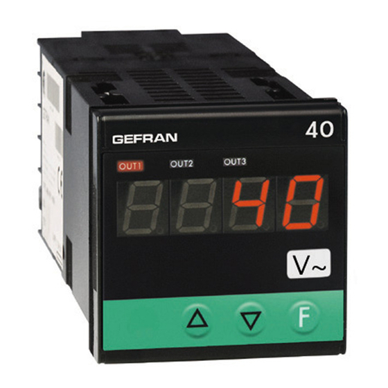
40A 48 / 40A 96
ALTERNATING CURRENT/VOLTAGE INDICATOR - INTERCEPTOR
70
70
45
45
115
70
92
!
For correct and safe
installation, follow the
instructions and observe
the warnings contained
in this manual.
USER'S MANUAL
SOFTWARE VERSION 1.0x / 2.0x
code 81661G / edition 10 - 09/2016
2 • TECHNICAL SPECIFICATIONS
Display
Keys
Accuracy
Resolution
Main input
Linear scale ranges
Alarms (set points)
Alarm masking
Relay contact
Logic output
Triac output
(option, only for 96 format)
Fault settings
Analog retransmission (option)
Logic input
Logic input functions
Power supply (switching)
Fuse (inside device, not
operator serviceable)
Faceplate protection
Working / Storage temperatures
Relative humidity
Environmental conditions of use
Installation
Weight
3, 4 digit red LED's
mod. 48 digit height 10mm (4 digits)
mod. 96 digit height 20mm (3 digits),
digit height 14mm (4 digits)
3 mechanical keys (Raise, Lower, F)
0.2% f.s. for 2 Vac, 20 Vac, 20mAac inputs
50mAac, 1Aac, at room temperature of 25° C
0.5% f.s. for 200Vac, 500Vac, 200mAac, 5Aac
inputs, values shown are for max. rms value with
sine wave signal
>13bit - 8000 points
2Vac, 20Vac, 200Vac, 500Vac, Ri ≥ 1MΩ
Max. continuous voltage = 600Vac
Max. voltage for 1 minute = 900Vac
Voltage pulse 1,2/50ms = 2Kvpeak
20mAac, 50mAac, 200mAac, Ri = 1,6Ω
Max. continuous current = 400mAac at 50°C
1Aac, 5Aac, Ri = 16mΩ
Max. continuous current = 5.5Aac at 50°C
Max. frequency = 60Hz
-1999 to 9999 (with 4 digit display)
-999 to 999 (with 3 digit display - only for model 96)
Configurable decimal point position
Maximum of three configurable alarms:
absolute, deviation, symmetrical deviation.
Adjustable hysteresis
- exclude on power-up
- latch reset from key and/or external contact
- insert delay filter (DON, DBI, DOF, DPO)
- set minimum intervention time
NO (NC) 5A, 250V
11VDC, Rout = 220 Ω (6V/20mA)
20...240Vac ±10%, 3A max
Snubberless, inductive and resistive load I
2
Alarm states can be configured in probe fault
condition
4 to 20mA, max. 150 Ω load
Ri=5.6KΩ (24v, 4mA), 1500 V isolation
configurable for alarm memory reset, hold, flash,
zero, selection of max., min. peak value, peak-peak
40A 48 (standard) 100...240Vac ±10% - 8VA
(optional) 20...27Vac/dc ±10% - 8VA
40A 96 (standard) 100...240Vac/dc ±10% - 7,5VA
(optional) 11...27Vac/dc ±10% - 5VA
50/60Hz
100 to 240Vac/dc - type T - 500mA - 250V
11 to 27Vac/dc - type T - 1.25A - 250V
IP65
0 to 50°C / -20 to 70°C
20 to 85%, non-condensing
for internal use only, altitude up to 2000m
Panel mounting, extractable from front
160g (mod. 48); 320g (mod. 96) for the complete version
t = 128A
2
S
1
Advertisement

Related Manuals for gefran 40A 48


Summary of Contents for gefran 40A 48
- Page 1 Use of these solvents can reduce the mechanical reliability of the device. Use a cloth dampened in ethyl alcohol or water to clean the external plastic case. SERVICE: GEFRAN has a service department. The warranty excludes defects caused by any use not conforming to these instructions.
- Page 2 3 • DESCRIPTION OF FACEPLATE Indication of output states: OUT 1 (Alarm 1); OUT 2 (Alarm 2); PV display: Indication of process variable •• OUT 3 (Alarm 3) Indication of ‘HI’ or ‘Lo’ out of range •• IIndication “Raise” and “Lower” keys: of off scale beyond the limits of positive calibration These keys are used for any operation that (br) and negative (Er) ••...
-
Page 3: Programming And Configuration
Device structure: identification of boards S5 = Status of Out 1 relay S6 = Status of Out 2 relay A = Direct POWER SUPPLY DISPLAY BOARD B = Inverse BOARD POWER SUPPLY BOARD S1 = Status of Out 3 relay A = Direct B = Inverse S5 = ON with digital input... - Page 4 • Information display Information display Format Decimal point position for XXXX main input scale XXX.X XX.XX X.XXX Software version Minimum limit of main min…max scale of input input scale and analog selected in t.P output Display of CPU type (alternated) and number of available outputs: A3 = with 3 outputs Maximum limit of main...
-
Page 5: User Calibration
• Protection Value Displayed Modifiable parameters parameters Protection code 0 not active: calculated status o.1, o.2, o.3 o.1, o.2, o.3 is sent directly to relay Output filter mode o.1, o.2 o.1, o.2 1 On delay (DON) 2 delay in activation of none output after output is turned off (DBI) - Page 6 6 • ALARMS Normal absolute alarm Symmetrical absolute alarm AL1 + [ H1 ] AL2 + H2 AL1 + H1 AL1 - [ H1 ] tempo tempo alarm 1 inverse direct alarm 2 For AL1 inverse absolute alarm (min.) with positive H1, 1 t = 1 For AL1 inverse absolute, symmetrical alarm with hysteresis H1, 1 t = 5 (*) = OFF if disabling on power-on exists For AL1 direct absolute, symmetrical alarm with hysteresis H1, 1 t = 4...
- Page 7 7 • ACCESSORIES • CURRENT TRANSFORMER These transformers are used to measure current at 50 ÷ 60Hz from 25A at 600A (rated primary current lp). The special characteristic of these transformers is the high number of turns of the secondary (ls). This produces a very low secondary current, appropriate for an electronic measurement circuit.
- Page 8 VAC. Resistors must be at least 2W); fit a 1N4007 diode in parallel with the coil of inductive loads that operate in DC. GEFRAN spa will not be held liable for any injury to persons and/or damage to property deriving from tampering, from any incorrect or erroneous use, or from any use not conforming to the device specifications.
Need help?
Do you have a question about the 40A 48 and is the answer not in the manual?
Questions and answers