Advertisement
Quick Links
1 • INSTALLATION
• Dimensions and cut-out: Panel mounting
108
96
48
44,5
105
10
Panel mounting:
Fix the device with the bracket provided before making any electrical connections.
To mount two or more devices side by side, use the cut-out dimensions shown above.
CE MARKING: EMC (electromagnetic compatibility) conformity to EEC Directive
89/336/CEE with reference to the generic Standard EN50082-2 (immunity in industrial
environments) and EN50081-1 (emission in residential environments). BT (low voltage)
conformity to Directive 73/23/CEE as modified by Directive 93/68.
MAINTENANCE: Repairs must be done out only by trained and specialized personnel.
Cut power to the device before accessing internal parts.
Do not clean the case with hydrocarbon-based solvents (Petrol, Trichlorethylene, etc.).
Use of these solvents can reduce the mechanical reliability of the device. Use a cloth
dampened in ethyl alcohol or water to clean the external plastic case.
SERVICE: GEFRAN has a service department. The warranty excludes defects caused
by any use not conforming to these instructions.
81671B_MHW_40F96_0308_ENG
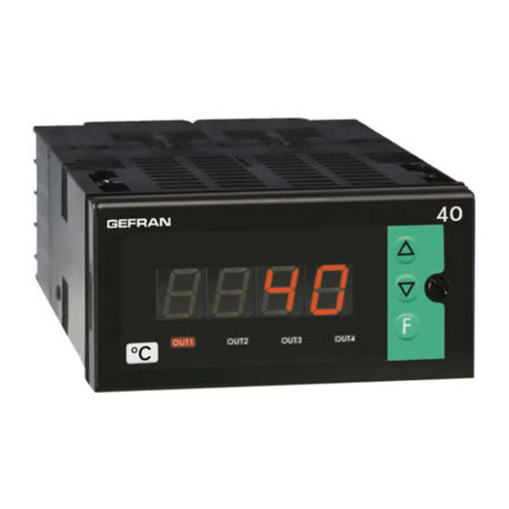
40F 96
CONFIGURABLE FREQUENCY INDICATOR - INTERCEPTOR
115
70
92
!
For correct and safe
installation, follow the
instructions and observe
the warnings contained
in this manual.
USER'S MANUAL
SOFTWARE VERSION 1.0x
code 81671B / edition 06 - 03/08
2 • TECHNICAL SPECIFICATIONS
Display
Keys
Accuracy
Main input
Scale limits
Sensor or transducer power supply
Alarms (set points)
Alarm masking
Relay contact
Logic output
Triac output (option)
Logic input
Logic input functions
Analog retransmission (option)
Power supply (switching)
Fuse (inside device, not
operator serviceable)
Faceplate protection
Working / Storage temperatures
Relative humidity
Environmental conditions of use
Installation
Weight
EMC conformity has been tested with the following connections
FUNCTION
Input
Power supply cable
Relay output cables
4 digit red LED's, digit height 14mm
3 mechanical keys (Raise, Lower, F)
0.1% in autorange mode ± 1 digit with fixed f.s.
- mechanical contact, no voltage, configurable in
opening/closing, 100Hz filter insertable from
configuration
- from logic control under voltage with amplitude
0.5...30 Vdc, 6 mA max, for proximity PNP or
NPN (inductive or capacitive), encoder or
NAMUR 2 or 3 wires
- maximum frequency of input signal with duty
cycle 50% settable 1, 2, 3, 4, 10, 20, 40, 100 KHz
- from alternate control 30...500V peak, 1 mA max.
maximum frequency 10KHz
minimum frequency 0.5Hz in sinusoidal mode
-1999...9999 (settable decimal point)
Can be converted into engineering units by
inserting a multiplier or divisor (for example, for
display / intercept of rpm)
5Vdc, 12 Vdc, 120mA max
24 Vdc ± 10%, 50mA max filtered only
Maximum of three configurable alarms:
absolute, deviation, symmetrical deviation.
Adjustable hysteresis
- exclude on power-up
- latch reset from key and/or external contact
- insert delay filter (DON, DBI, DOF, DFO)
- set minimum intervention time
NO (NC) 5A, 250V a cosϕ=1
type D 11Vdc, Rout = 220Ω (6V/20mA)
20...240Vac ±10%, 3A max.
Snubberless, inductive and resistive load
I
2
t = 128A
2
S
Ri = 5,6KΩ (24V, 4mA), 1500V isolation
configurable for alarm memory reset, hold, flash,
zero, selection of max., min. peak value, peak-
peak
4 to 20mA, max. 150 Ω load
(standard) 100...240Vac/dc ±10% max 11,5VA
(optional) 11...27Vac/dc ±10% max 9VA
50/60Hz
100 to 240Vac/dc - type T - 500mA - 250V
11 to 27Vac/dc - type T - 1.25A - 250V
IP65
0 to 50°C / -20 to 70°C
20 to 85%, non-condensing
for internal use only, altitude up to 2000m
Panel mounting, extractable from front
320g for the complete version
CABLE
LENGTH USED
1 mm
2
3 m
1 mm
2
1 m
1 mm
2
3,5 m
1
Advertisement

Related Manuals for gefran 40F 96


Summary of Contents for gefran 40F 96
- Page 1 FUNCTION CABLE LENGTH USED SERVICE: GEFRAN has a service department. The warranty excludes defects caused Input 1 mm by any use not conforming to these instructions. Power supply cable...
- Page 2 3 • DESCRIPTION OF FACEPLATE Flashing LED: When frequency of input signal exceeds value set for parameter PS “Raise” and “Lower” keys: PV display: Indication of process variable These keys are used for any operation that •• Indication of ‘HI’ or ‘Lo’ out of range requires a numerical parameter to be raised or ••...
-
Page 3: Programming And Configuration
Device structure: identification of boards CPU BOARD + POWER SUPPLY BOARD Sensor power supply ON OFF 12V OFF ON OUTPUT BOARD S3 S1 24V OFF OFF DISPLAY BOARD FL1, R20 on component side are to be removed to obtain isolation in case of high voltage AC input S1 = Status of Out 1 relay S2 = Status of Out 2 relay S3 = Status of Out 3 relay... - Page 4 • Input parameters • Output parameters Output settings Input settings Number of outputs 0 to 3 0 Frequency - input NPN Input 1 Frequency - input PNP configuration 2 AC input 1. t - 2. t - 3. t Value Direct Absolute Normal...
- Page 5 • HOLD function The input value and alarms are frozen while the logic input is active. With the logic input active, a reset turns OFF both the relay outputs and the alarms latch. • FLASH function Input value is sampled; state of alarms is not transferred to outputs; outputs are “frozen”. When the logic input is active the input value is “frozen”...
- Page 6 • Filter - outputs with reference to parameters F.0 and r.A The diagrams refer to a normal absolute alarm with hysteresis H = 0 F.0 = 2 F.0 = 1 DBI = Delay in turning on output after output is DON = Delayed activation turned off Alarm...
- Page 7 numerator denominator numerator • denominator where: fs = full scale [ KHz ] (can be chosen from 1, 2, 4, 10, 20, 40, 100KHz according to max. frequency in input) = multiplier = divisor These parameters can be set on the “In” menu EXAMPLE 1 = 80 mm (motor pulley diameter) = 160 mm (encoder pulley diameter)
-
Page 8: Order Code
VAC. Resistors must be at least 2W); fit a 1N4007 diode in parallel with the coil of inductive loads that operate in DC. GEFRAN spa will not be held liable for any injury to persons and/or damage to property deriving from tampering, from any incorrect or erroneous use, or from any use not conforming to the device specifications.
Need help?
Do you have a question about the 40F 96 and is the answer not in the manual?
Questions and answers