Table of Contents
Advertisement
Quick Links
Notice
Hewlett-Packard to Agilent Technologies Transition
This manual may contain references to HP or Hewlett-Packard. Please note that Hewlett-Packard's
former test and measurement, semiconductor products and chemical analysis businesses are now part of
Agilent Technologies. To reduce potential confusion, the only change to product numbers and names has
been in the company name prefix: where a product name/number was HP XXXX the current name/
number is now Agilent XXXX. For example, model number HP8648 is now model number Agilent
8648.
To contact Agilent Technologies please use the information below.
Online assistance:
Americas
Canada
1 877 894 4414
Asia Pacific
Australia
1 800 629 485
India
1 800 112 929
Malaysia
1 800 888 848
Thailand
1 800226 008
Europe & Middle East
Austria
43 (0) 1 360 277 1571
Finland
358 (0) 10 855 2100
Ireland
1890 924 204
Netherlands
31 (0) 20 547 2111
Switzerland
0800 80 53 53
Other European Countries:
Please note that this document was updated in April 2011 to revise the Mixer Non-Linearity
Table 14-13 on page 14-37.
http://www.agilent.com/find/assist
Latin America
(305) 269 7500
China
800 810 0189
Japan
0 120 (421) 345
Singapore
1 800 375 8100
Belgium
32 (0) 2 404 93 40
France
0825 010 700*
*0.125 Euros/minute
Israel
972-3-9288-504/544
Spain
34 (91) 631 3300
United Kingdom
44 (0) 118 9276201
http://www.agilent.com/find/contactus
United States
1 800 829 4444
Hong Kong
800 938 693
Korea
080 769 0800
Taiwan
0800 047 866
Denmark
45 70 13 15 15
Germany
49 (0) 7031 464 6333
Italy
39 02 92 60 8484
Sweden
0200-88 22 55
Advertisement
Table of Contents

Related Manuals for HP 70427A


Summary of Contents for HP 70427A
- Page 1 Agilent Technologies. To reduce potential confusion, the only change to product numbers and names has been in the company name prefix: where a product name/number was HP XXXX the current name/ number is now Agilent XXXX. For example, model number HP8648 is now model number Agilent 8648.
- Page 2 HP 70427A HP 70428A (including Opt. 002) Serial Numbers: HP 70427A - 3240A and Above, HP 70428A - 3240A and Above User’s Guide HP part number: 70427-90002 Printed in USA June 2014 Supercedes: May 2014...
-
Page 3: Notice
(c)(1) and (c)(2) of the Commercial Computer Software Restricted Rights clause at FAR 52.227-19 for other agencies. Hewlett-Packard Company Santa Rosa Systems Division 1400 Fountaingrove Parkway Santa Rosa, CA 95403-1799, U.S.A. © Copyright Hewlett-Packard Company 1993, 1998, 1999 ii HP 70427A/HP 70428A User’s Guide... -
Page 4: What You'll Find In This Manual
• Chapter 11, “Connectors and Indicators (Front- and Rear-Panel)” • Chapter 12, “Remote Programming Commands” • Chapter 13, “Block Diagram” • Chapter 14, “Performance Tests” • Chapter 15, “Adjustments” • Chapter 16, “Customer Support” HP 70427A/HP 70428A User’s Guide iii... -
Page 5: Warranty
Buyer. However, Buyer shall pay all shipping charges, duties, and taxes for products returned to HP from another country. HP warrants that its software and firmware designated by HP for use with an instrument will execute its programming instructions when properly installed on that instrument. -
Page 6: Assistance
EXCLUSIVE REMEDIES. THE REMEDIES PROVIDED HEREIN ARE BUYER’S SOLE AND EXCLUSIVE REMEDIES. HP SHALL NOT BE LIABLE FOR ANY DIRECT, INDIRECT, SPECIAL, INCIDENTAL, OR CONSEQUENTIAL DAMAGES, WHETHER BASED ON CONTRACT, TORT, OR ANY OTHER LEGAL THEORY. Assistance Product maintenance agreements and other customer assistance agreements are available for Hewlett-Packard products. -
Page 7: Sound Emission
According to ISO 7779:1988/EN 27779:1991 (Type Test) ____________________________________________________ Herstellerbescheinigung Diese Information steht im Zusammenhaug mit den Anforderungen der MaschinenlXrminformationsverordnung vom 18 Januar 1991. • Schalldruckpegel Lp <70 dB(A). • Am Arbeitsplatz. • Normaler Betrieb. • Nack ISO 7779:1988/EN 27779:1991 (TypprXfung). vi HP 70427A/HP 70428A User’s Guide... -
Page 8: Service And Support
Any adjustment, maintenance, or repair of this product must be performed by qualified personnel. Contact your customer engineer through your local HP Service Center. You can find a list of HP Service Centers on the web at http://www.hp.com/go/tmdir If you do not have access to the Internet, one of these HP centers can direct... -
Page 9: Safety And Regulatory Information
The CE mark is a registered trademark of the European Community. If it is accompanied by a year, it indicates the year the design was proven. The CSA mark is a registered trademark of the Canadian Standards Association. viii HP 70427A/HP 70428A User’s Guide... -
Page 10: Safety Earth Ground
If this product is to be powered by autotransformer, make sure the common terminal is connected to the neutral (grounded) side of the ac power supply. HP 70427A/HP 70428A User’s Guide ix... -
Page 11: Declaration Of Conformity
Declaration of Conformity x HP 70427A/HP 70428A User’s Guide... -
Page 12: Typeface Conventions
Typeface Conventions Typeface Conventions • Italics Used to emphasize important information: Use this software only with the HP xxxxxX system. • Used for the title of a publication: Refer to the HP xxxxxX System-Level User’s Guide. • Used to indicate a variable: Type filename. - Page 13 Typeface Conventions -xii HP 70427A/HP 70428A User’s Guide...
-
Page 14: Table Of Contents
Procedure ..........1-15 Procedure B: Setting HP-IB Address ......1-18 Overview . - Page 15 Millimeter wave downconverting ......2-3 Using the HP 70427A as a Microwave source ....2-4 To Access the Downconverter Screen .
- Page 16 Table 4-1. Tuning Sensitivity ....... 4-4 Table 4-2. HP 700428A Reference Chain Parameters ... . 4-5 Table 4-3.
- Page 17 Sample HP-IB programs ........7-12...
- Page 18 Overview ..........9-1 HP 71707A/70427A Specifications ......9-2 Microwave Downconverter .
- Page 19 General Specifications ....... 9-21 HP 71708A/70428A Specifications ......9-25 Microwave Source .
- Page 20 HP-IB ADDRESS ........
- Page 21 RETUNE YTF ..........Contents-viii HP 70427A/HP 70428A User’s Guide...
- Page 22 HP-IB indicators ........
- Page 23 Characteristics ........11-30 Contents-x HP 70427A/HP 70428A User’s Guide...
- Page 24 Table 12-3. IEEE 488.2 COMMON COMMANDS ... . . 12-4 Table 12-4. INSTRUMENT SELECT COMMAND....12-4 Table 12-5. DOWNCONVERTER COMMANDS (HP 70427A only) ..12-5 Table 12-6.
- Page 25 Table 13-21. Step Gain Amplifier Selection ....13-57 HP 70427A AM Detector Filter ......13-60 Overview .
- Page 26 Procedure ..........14-57 Table 14-20. Spec Lines: 2.4 GHz (Test 8) ....14-61 HP 70427A/HP 70428A User’s Guide Contents-xiii...
- Page 27 Table 14-33. Am Detector Noise Floor ..... 14-83 Table 14-34. HP 70428/002 .05ppm/V Tuning ....14-84 Table 14-35.
-
Page 28: Installation
HP 71708A Option 002)). Does not require HP-IB or MS-IB. Figure 1-1 Installed in a Stand Alone Mainframe Example B In a mainframe with no display linked to a computer via HP-IB. Requires HP-IB. Figure 1-2 Installed in a Main frame with No Display Linked to a Computer... -
Page 29: Installation Overview
Thoroughly read the connector care booklet enclosed, to ensure proper care of the connectors. Installation Overview The installation procedure for the HP 7042X varies depending on the selected configuration. It may include one or more of the following major steps: 1. - Page 30 Installation 5. Software configuration: entering the appropriate soft and hard key configurations. For MMS information beyond what is included in this manual, refer to the appropriate MMS manual. HP 70427A/HP 70428A User’s Guide 1-3...
-
Page 31: Standard Equipment Supplied
Verify that all parts are present and inspect for damage. If a part is missing or damaged contact your nearest Hewlett-Packard Sales or Service Office. Figure 1-4 Standard HP Equipment Supplied with the Module 1-4 HP 70427A/HP 70428A User’s Guide... -
Page 32: Optional Equipment
HP 7042 70428A Option Option 915 Service-Manuals-On-a-dis 70427-90003 70428-90007 70428-90008 HP 70428 K03 (Special Service Tools and Option) Accessory Kit HP 70428 K01 Tune Voltage Supply HP 70427A K02 Balun HP 3048A K21 Filter HP 70427A/HP 70428A User’s Guide 1-5... -
Page 33: Front Panel
Signal Input, and RF Analyzer Output. 2. Connect item B (type N to SMA adapter) to IF output. 3. Connect item C (50 ohm termination) to type N to SMA adapter. Figure 1-5 HP 70427A Connector Installation 1-6 HP 70427A/HP 70428A User’s Guide... - Page 34 Connect item A (3.5 APC connector saver) to: Microwave LO Output Figure 1-6 HP 70428A Connector Installation HP 70428A Option 002 • Connect item A (3.5 APC connector savers) to: Microwave LO Output, RF Output. Figure 1-7 HP 70428A Option 002 Connector Installation HP 70427A/HP 70428A User’s Guide 1-7...
-
Page 35: Rear Panel
50 OHM Terminations Installation The 50 ohm terminations for the rear panel are the same for each of the HP 70427A, HP 70428A, and HP 70428A Option 002. 1. Connect item C to: Buffered 10 MHz Out, 100 MHz Out+8 dBm, 600 MHz Out + 20 dBm 2. -
Page 36: Preliminary Work
MMS manual for troubleshooting before continuing with the installation procedure. Set MS-IB Address (if If your module will be controlled via HP-IB, set the HP-IB address to a location that does not conflict with any other module in your MMS system. Necessary) Refer to procedure B at the end of this chapter for instructions to set HP-IB/MS-IB address. -
Page 37: Mainframe Assembly
Install Unit 1. Slide the Unit into the mainframe. Figure 1-9 Unit Installation 2. Tighten the bolt using the 8-mm hex ball driver. Then close lid. Figure 1-10 Tightening Bolt using 8-mm Hex Ball Driver 1-10 HP 70427A/HP 70428A User’s Guide... -
Page 38: Connect Cables
Installation Mainframe Assembly Connect Cables If HP-IB is required for your configuration, install HP-IB cable. Figure 1-11 HP-IB Cable Installation Plug in and power up. Verify that the unit is working: a. Six LED’s on the front panel will illuminate for about six seconds, then blink off. -
Page 39: Verification
1. Press The softkey. Freqs Figure 1-12 Softkey Location Freqs 2. Press the softkey. INPUT FREQ Figure 1-13 Softkey Location INPUT FREQ 3. Enter 10 with the numeric keypad. 4. Then press the softkey. 1-12 HP 70427A/HP 70428A User’s Guide... - Page 40 HP 70428A Verification: 1. Press the softkey. Output Figure 1-15 Softkey Location Output 2. Press the softkey. FREQ Figure 1-16 FREQ Softkey Location HP 70427A/HP 70428A User’s Guide 1-13...
- Page 41 If you are installing an HP 70428A Option 002 using an HP 8662A or HP 8663A, additional softkey configurations are necessary. See procedure A at the end of this chapter. If you are installing an HP 70427A or HP 70428A into a mainframe with a display, installation is complete. CAUTION After installation is complete, consult the operation guide for proper use of the instrument.
-
Page 42: Procedure A: Hp 70428A Option 002, Using Hp 8662A / Hp 8663A Softkey Configuration
Installation Procedure A: HP 70428A Option 002, using HP 8662A / HP 8663A Procedure A: HP 70428A Option 002, using HP 8662A / HP 8663A Softkey Configuration Procedure 1. Press the softkey. Service Figure 1-19 Softkey Location Service 2. Press the softkey. - Page 43 Installation Procedure A: HP 70428A Option 002, using HP 8662A / HP 8663A 4. Press the softkey. HP 8662 HP 8663A Figure 1-22 Softkey Location HP 8662 HP 8663A Press the softkey. The enter HP - IB Address HP-IB ADDRESS...
- Page 44 Installation Procedure A: HP 70428A Option 002, using HP 8662A / HP 8663A 6. Press the softkey. Output Figure 1-25 Softkey Location Output Installation is now complete. HP 70427A/HP 70428A User’s Guide 1-17...
-
Page 45: Procedure B: Setting Hp-Ib Address
HP-IB default address. This procedure is described below: 1. The MS-IB row switches for the HP 70427A, HP 70428A, and the HP 70428A Option 002 must be set to “zero” (because each of these modules is a master in the system). -
Page 46: Getting Started
Getting Started Overview This chapter contains basic operating instructions for the HP 70427A Downconverter, HP 70428A Microwave Source, and the HP 70428A Option 002 Microwave Source (tunable source). Figure 2-1 Models HP 70427A, HP 70428A, HP 70428A Option 002 HP 70427A/HP 70428A User’s Guide 2-1... -
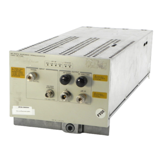
Page 47: Hp 70427A Microwave
Figure 2-2 HP 70427A Microwave Downconverter Microwave The HP 70427A Downconverter accepts signals between 5 MHz and 26.5 GHz at levels from –30 dBm to +30 dBm. Signals above 1.5 GHz are Downconverting mixed with an internal low-noise local oscillator (LO), which tunes in 600 MHz steps, resulting in an intermediate frequency (IF) between 300 and 900 MHz. -
Page 48: Detecting Am Noise At The If Output
VOLTAGE CONTROL connector. Figure 2-3 Reference Chain Millimeter wave The downconverter’s range can be extended to 110 GHz by adding an external millimeter (mm) wave harmonic mixer. In mm mode the downconverting HP 70427A/HP 70428A User’s Guide 2-3... -
Page 49: Using The Hp 70427A As A Microwave Source
IF between 5 MHz and 1.2 GHz. Using the HP 70427A The HP 70427A includes the functions of the HP 70428A Microwave Source. When the module is used as a downconverter, the source hardware as a Microwave source functions as the internal local oscillator (LO). -
Page 50: To Access The Downconverter Screen
Step 1 - Make the downconverter the active module Look at the ACT indicator on the HP 70427A’s front panel. If it is lit, the module is active and can be controlled by the MMS display. If it is not lit do the following: 1. - Page 51 Getting Started To Access the Downconverter Screen Step 2 - Display the downconverter screen 1. Press the key. INSTR PRESET Figure 2-5 Downconverter Display 2-6 HP 70427A/HP 70428A User’s Guide...
-
Page 52: To Read Error Messages
REPORT ERRORS Figure 2-6 Message Error Access Step 2 - Look up the error messages Error messages are described in the Messages section in the back of this manual. Figure 2-7 Error Message Manual Sample HP 70427A/HP 70428A User’s Guide 2-7... - Page 53 Step 3 - Clear the messages Press the softkey repeatedly until " " is REPORT ERRORS No Errors displayed. If the condition that caused the error still exists the error message will re-appear. Figure 2-8 Report Errors Softkey 2-8 HP 70427A/HP 70428A User’s Guide...
-
Page 54: To Downconvert A Signal Below 26.5 Ghz
1 of 2 3. Press the softkey. INPUT ATTEN 4. Enter an attenuation up to 35 dB in 5 dB steps with the numeric keys. 5. Complete the entry by pressing the softkey. HP 70427A/HP 70428A User’s Guide 2-9... - Page 55 This must be done after a signal is connected (see step 3 below). Step 3 - Connect the cables 1. The signal to be downconverted goes to the input SIGNAL connector. 2. The IF output is taken from the IF output connector. 2-10 HP 70427A/HP 70428A User’s Guide...
- Page 56 1 of 2 3. Press the softkey. IF GAIN 4. Enter an IF gain between –10 and +45 dB in 5 dB steps with the numeric keypad. 5. Complete the entry by pressing the softkey. HP 70427A/HP 70428A User’s Guide 2-11...
- Page 57 1. Press the softkey Amplitudes 2. Press the softkey more 1 of 2 3. Press the softkey. AUTO IF GAIN Auto-ranging sets the IF gain for an IF output level between 0 dBm and +6 dBm. 2-12 HP 70427A/HP 70428A User’s Guide...
-
Page 58: To Demodulate Am: Rf Am Detector
Downconverter Screen Display Diagram Step 2 - Select AM mode 1. Press the softkey. AM Noise 2. Press the softkey so that is underlined. AM NSE IN | IF Figure 2-14 Select AM Mode Display Diagram HP 70427A/HP 70428A User’s Guide 2-13... - Page 59 1. The signal to be detected goes to the input SIGNAL connector. 2. The demodulated signal is taken from the AM NOISE output connector. This output is AC coupled. Figure 2-15 Connect Cables Diagram 2-14 HP 70427A/HP 70428A User’s Guide...
- Page 60 The optimum range is +10 to +15 dBm. To Automatically Adjust the Input Attenuation Another way to adjust the input attenuation is to trigger a one-time auto-ranging. To do this press the softkey. AUTO ATTEN HP 70427A/HP 70428A User’s Guide 2-15...
-
Page 61: To Demodulate Am: If Am Detector
Make sure the AM noise mode is set to IF. To do this press the AM Noise softkey and look at the softkey. It must have underlined. AM NSE IN | IF Figure 2-17 AM: IF AM Display Diagram 2-16 HP 70427A/HP 70428A User’s Guide... - Page 62 Step 1 - Set up the downconverter to downconvert a signal 1. Enter the input frequency. 2. Set input attenuation and/or IF gain if necessary. 3. Connect the signal to be downconverted and demodulated to the SIGNAL connector. Figure 2-18 Downconverter Signal Setup HP 70427A/HP 70428A User’s Guide 2-17...
- Page 63 4. Select the output by pressing one of the following softkeys: • softkey selects the AM NOISE connector. IF AM NOISE • softkey selects the IF LEVEL connector. IF LEVEL Figure 2-19 Detector’s Output Selection Diagram 2-18 HP 70427A/HP 70428A User’s Guide...
-
Page 64: To Electrically Tune The Downconverter's Lo
Step 1 - Select the tuning sensitivity 1. Press the softkey. Ref Chain 2. Press the softkey. Tune Sens 3. Press the , or softkey. .05 ppm/v 1.0 ppm/v 20 ppm/v Figure 2-20 Tuning Sensitivity Diagram HP 70427A/HP 70428A User’s Guide 2-19... - Page 65 Tuning with a Sensitivity of 20 ppm/V With a 20 ppm/V tuning sensitivity the reference chain’s 600 MHz oscillator is free running. A 1 Volt tuning voltage with cause a 20 ppm change in the downconverter’s LO frequency. 2-20 HP 70427A/HP 70428A User’s Guide...
-
Page 66: To Select The Lo's Reference Chain Phase-Lock-Loop Bandwidth
3. Note which sensitivity (on the right side of the screen) is underlined. Figure 2-22 Reference Chain Phase-Lock-Loop-Bandwidth Diagram The 100 MHz and/or 600 MHz phase-lock-loop bandwidths can be set depending on the tuning sensitivity. See the following table: HP 70427A/HP 70428A User’s Guide 2-21... -
Page 67: Bandwidths And Tuning Sensitivity
1. Press the softkey. Ref Chain 2. Press either the softkey. 100 MHz PLL BW 600 PLL BW 3. Press the softkey that corresponds to the desired bandwidth. Figure 2-23 Tuning the Sensitivity Setting Diagram 2-22 HP 70427A/HP 70428A User’s Guide... -
Page 68: To Control The Downconverter Over The Hp-Ib (Ieee 488.2)
Look in the upper left corner of the display. The model number of the module followed by its HP-IB address in parentheses should be displayed. The two last two digits after the comma are the last two digits of the address. - Page 69 HP-IB Connection Diagram Step 3 - Enter a program and run it The following Diagram is for the HP BASIC on a HP 9000 series 200/300 controller. It sets the downconverter’s frequency, input attenuation, and IF level. Chapter 12 has a complete table of HP-IB commands.
-
Page 70: To Configure The Downconverter As A Microwave Source
Source 1. Press the softkey. source The HP 70428A menus and screens will be displayed. Follow the operating instructions for the source. Frequency and amplitude settings are preserved in the source and downconverter when switching back and forth. HP 70427A/HP 70428A User’s Guide 2-25... -
Page 71: Hp 70428A Microwave Source Module Overview
HP 70428A Microwave Source Module Overview HP 70428A Microwave Source Module Overview The HP 70428A Microwave Source Module outputs a signal between GHz and 26.4 GHz, in 600 MHz steps, at levels from 0 dBm up to +16 dBm (+10 dBm above 7.2 GHz). -
Page 72: To Access The Source Screen
Step 1 - Make the Source the active module Look at the ACT indicator on the HP 70428A’s front panel. If it is lit, the module is active and can be controlled by the MMS display. If it is not lit do the following: 1. - Page 73 Step 2 - Display the Source Screen Press the key (if the module is an HP 70427A or INSTR PRESET HP 70428A Option 002), access the source screen by pressing the source softkey. Figure 2-29 HP 70427A and HP 70428A Option 002 Source Screen...
-
Page 74: To Read Error Messages
REPORT ERRORS Figure 2-30 Message Error Access Step 2 - Look up the error messages Error messages are described in the Messages section in the back of this manual. Figure 2-31 Error Message Manual Sample HP 70427A/HP 70428A User’s Guide 2-29... - Page 75 Step 3 - Clear the messages Press the softkey repeatedly until " " is REPORT ERRORS No Errors displayed. If the condition that caused the error still exists the error message will re-appear. Figure 2-32 Report Errors Softkey 2-30 HP 70427A/HP 70428A User’s Guide...
-
Page 76: To Output A Signal With A Microwave Source
The module’s firmware will round off the entered frequency to the nearest 600 MHz. It will ignore frequencies outside the above range. The firmware will also set the power to 0 dBm. Figure 2-33 Microwave Source Signal Softkeys Locations HP 70427A/HP 70428A User’s Guide 2-31... -
Page 77: Press The .05 Ppm/V , 1.0 Ppm/V , Or 20 Ppm/V
But the minimum specified power is shown below. • 2.4 to 6.6 GHz:+16 • 7.2 to 25.8 GHz: +10 Also, the actual resolution can be as much as 0.2 dB. 4. Press the softkey. Figure 2-34 Output Power Softkey Locations 2-32 HP 70427A/HP 70428A User’s Guide... -
Page 78: To Electrically Tune The Source's Frequency
Step 1 - Select the tuning sensitivity 1. Press the softkey. Ref Chain 2. Press the softkey. Tune Sens 3. Press the , or softkey. 0.05 ppm/V 1.0 ppm/V 2.0 ppm/V Figure 2-35 Electrically Tune Source’s Softkeys HP 70427A/HP 70428A User’s Guide 2-33... - Page 79 Tuning with a Sensitivity of 20 ppm/V With a 20 ppm/V tuning sensitivity the reference chain’s 600 MHz oscillator is free running. A 1 Volt tuning voltage with cause a 20 ppm change in the source’s output fequency. 2-34 HP 70427A/HP 70428A User’s Guide...
-
Page 80: To Select Reference Chain Phase-Lock-Loop Bandwidth
The 100 MHz and /or 600 MHz bandwidth can be set depending on the tuning sensitivity. Tuning Sensitivity Bandwidth can be set for: 0 ppm 100 MHz and or 600 MHz phase-lock-loops. 0.5 ppm/V 100 MHz and or 600 MHz phase-lock-loops. HP 70427A/HP 70428A User’s Guide 2-35... - Page 81 Step 2 - Select the bandwidth. 1. Press the softkey. Ref Chain 2. Press either softkey. 100 MHz PLL BW 600 MHz PLL BW 3. Press the softkey that corresponds to the desired bandwidth. Figure 2-38 Bandwidth Softkey Locations 2-36 HP 70427A/HP 70428A User’s Guide...
-
Page 82: To Control The Source Over The Hp-Ib (Ieee 488.2)
Step 1 - Determine the sources HP-IB address Look in the upper left corner of the display. The model number of the module followed by its HP-IB address in parentheses should be displayed. The two digits after the coma are the last two digits of the address. - Page 83 HP-IB Cable Connection Step 3 - Enter a program and run it. The following is for HP BASIC on an HP 9000 series 200/300 controller. It sets the source’s frequency and output power. Chapter 12 has a complete table of HP-IB commands.
-
Page 84: Hp 70428A Option 002 (Tunable Source) Overview
Overview The HP 70428A Option 002 Microwave Source Module (Tunable Source) up-converts and HP 8662/3A signal generator’s output into the 2.4 GHz to 26.5 GHz range. It consists of a microwave source as described in the previous section and a mixer with a second YIG-tuned-filter. -
Page 85: To Access The Tunable Source Screen
Step 1 - Make the tunable source the active module. Look at the ACT indicator on the HP 70428A Option 002’s front panel. If it is lit, the module is active and can be controlled by the MMS display. If it is not lit do the following: 1. - Page 86 Getting Started To Access the Tunable Source Screen Step 2 - Display the tunable source 1. Press the key. INSTR PRESET Figure 2-44 key location INSTR PRESET HP 70427A/HP 70428A User’s Guide 2-41...
-
Page 87: To Read Error Messages
REPORT ERRORS Figure 2-45 Message Error Access Step 2 - Look up the error messages Error messages are described in the Messages section in the back of this manual. Figure 2-46 Error Message Manual Sample 2-42 HP 70427A/HP 70428A User’s Guide... - Page 88 Step 3 - Clear the messages Press the softkey repeatedly until " " is REPORT ERRORS No Errors displayed. If the condition that caused the error still exists the error message will re-appear. Figure 2-47 Report Errors Softkey HP 70427A/HP 70428A User’s Guide 2-43...
-
Page 89: To Output A Signal With The Tunable Source
2. Connect an RF cable between the signal generator’s RF OUTPUT connector and the HP 70428A Option 002’s HP 8662A connector. NOTE The HP 70428A Option 002 acts as a controller. There must be no other controller connected to the bus. 2-44 HP 70427A/HP 70428A User’s Guide... - Page 90 1. Press the softkey. Service 2. Press the softkey. Misc 3. Press the softkey. RF Source 4. Press the softkey. HP 8662A HP 8663A 5. Press the softkey. EXIT Figure 2-49 Signal Generator Type Selection HP 70427A/HP 70428A User’s Guide 2-45...
- Page 91 To Output a Signal with the Tunable Source Step 3 - Enter the generator’s HP-IB address 1. Press the softkey HP-IB ADDRESS 2. Enter the signal generator’s HP-IB address with the numeric keypad. 3. Press the softkey to complete the entry. ENTER Figure 2-50 HP-IB Address Key Locations 2-46 HP 70427A/HP 70428A User’s Guide...
- Page 92 OUTPUT FREQ 3. Key in a frequency between 2.4 GHz and 26.5 GHz with the numeric keyboard. 4. Press the , or softkey to complete the entry. Figure 2-51 Output Frequency Softkey Locations HP 70427A/HP 70428A User’s Guide 2-47...
- Page 93 2.4 to 6.6 GHz:+16 • 6.6 to 25.8 GHz: +10 Also actual resolution can be as much as 0.2 dB. 3. Press the softkey to complete the entry. Figure 2-52 Output Power Softkey Locations 2-48 HP 70427A/HP 70428A User’s Guide...
-
Page 94: To Electrically Tune The Tunable Source's Frequency
Step 1 - Select the tuning sensitivity 1. Press the softkey. Ref Chain 2. Press the softkey. Tune Sens 3. Press the , or softkey. 0.05 ppm/V 1.0 ppm/V 2.0 ppm/V Figure 2-53 Electrically Tune Softkeys HP 70427A/HP 70428A User’s Guide 2-49... - Page 95 Tuning with a Sensitivity of 20 ppm/V With a 20 ppm/V tuning sensitivity the reference chain’s 600 MHz oscillator is free running. A 1 Volt tuning voltage with cause a 20 ppm change in the source’s output fequency. 2-50 HP 70427A/HP 70428A User’s Guide...
-
Page 96: To Select Reference Chain Phase-Lock-Loop Bandwidth
The 100 MHz and /or 600 MHz bandwidth can be set depending on the tuning sensitivity. Tuning Sensitivity Bandwidth can be set for: 0 ppm 100 MHz and or 600 MHz. phase-lock-loops 0.5 ppm/V 100 MHz and or 600MHz phase-lock-loops. 1.0 ppm/V 600 MHz phase-lock-loop. HP 70427A/HP 70428A User’s Guide 2-51... - Page 97 Step 2 - Select the bandwidth. 1. Press the softkey. Ref Chain 2. Press either softkey. 100 MHz PLL BW 600 MHz PLL BW 3. Press the softkey that corresponds to the desired bandwidth. Figure 2-56 Bandwidth Softkey Locations 2-52 HP 70427A/HP 70428A User’s Guide...
-
Page 98: To Configure The Tunable Source As A Microwave Source
Getting Started To Configure the Tunable Source as a Microwave Source To Configure the Tunable Source as a Microwave Source Procedure 1. Press the softkey. The HP 70428A menus and screens will be Source displayed. Figure 2-57 Softkey Location Source 2. - Page 99 Getting Started To Configure the Tunable Source as a Microwave Source 2-54 HP 70427A/HP 70428A User’s Guide...
-
Page 100: Downconverter Operation
Downconverter Module with the HP 3048A and HP 3047A Phase Noise Measurement Systems. Procedures The first four procedures are for user control of the HP 70427A for use with either the HP 3048A or HP 3047A systems. • Phase Noise Measurement <26.5 GHz ....User Control •... -
Page 101: Phase Noise Measurement <26.5 Ghz User Control
This procedure can be used for all HP 3048A and HP 3047A software versions. The HP 70427A is controlled manually. The HP 70427A noise specifications in chapter 9 of the manual are provided for the HP 70427A alone and combined with the HP 8662A or HP 8663A used as the reference source. -
Page 102: Procedure
HP 8662A/3A’s EFC can only track a drift of 10 of the output frequency from the downconverter. The HP 8662A/3A can also be tuned by setting the modulation to DC FM. Refer to the HP 3048A manual for more information on tuning the HP 8662A/3A. - Page 103 Refer to the specification table in chapter 9 for noise performance for each tuning sensitivity. Tuning the DUT: Refer to the Signal Source Applications chapter of the HP 3048A manual for information on tuning the DUT. Step 4 - Select the downconverter tuning sensitivity Do this only if the downconverter is being used.
- Page 104 Determining PHASE DETECTOR CONSTANT: Measure the Detector Constant. Determining the VCO TUNING CONSTANT: Measure the VCO Tuning Constant (unless the HP 8662/3A is being tuned with the DC FM, then it should be computed). The Computed PLL Suppression WILL be verified.
- Page 105 Tuning Constant Voltage Tuning Range of VCO). If the reference source is under system control it will be tuned automatically. After the beatnote is within the limits the system asks for, proceed with the measurement. 3-6 HP 70427A/HP 70428A User’s Guide...
-
Page 106: Millimeter Phase Noise Measurement - User Control
This procedure can be used for all HP 3048A and HP 3047A software versions. The HP 70427A is controlled manually. The HP 8662A and HP 8663A can be used under system control with the any HP 3048A software version. See the HP 3048A manual for details. -
Page 107: Procedure
MMS display when the input frequency was entered, do the following: • Press the softkey until ON is underlined. BIAS ON | OFF The mixer bias will be adjusted in step 11. 3-8 HP 70427A/HP 70428A User’s Guide... - Page 108 HP 8662A/3A’s EFC can only track a drift of 10 of the output frequency from the downconverter. The HP 8662A/3A can also be tuned by setting the modulation to DC FM. Refer to the HP 3048A manual for more information on tuning the HP 8662A/3A.
- Page 109 Determining the PHASE DETECTOR CONSTANT: Measure the Detector Constant. Determining the VCO TUNING CONSTANT: Measure the VCO Tuning Constant (unless the HP 8662A/3A is being tuned with DC FM, then it should be computed). The Computed PLL Suppression WILL be verified.
- Page 110 (as measured by the RF spectrum analyzer). 4. Adjust mixer bias for a maximum IF signal measured by the spectrum analyzer. a. Press the softkey. Freqs b. Press the softkey. MIXER BIAS HP 70427A/HP 70428A User’s Guide 3-11...
- Page 111 When the downconverter is configured for mm operation don’t apply a μ high-level microwave signal to the input. Change the mode back to W and press the key. This will protect the IF amplifier from damage. INSTR PRESET 3-12 HP 70427A/HP 70428A User’s Guide...
-
Page 112: Am Noise Measurement (Input Am Detector) User Control
5 MHz to 26.5 GHz and produces a baseband signal. This procedure can be used for all HP 3048A and HP 3047A Phase Noise measurement software. The HP 70427A is controlled manually. With HP 3048A software versions A.03.00, or later, the HP 70427A can be controlled by the software. - Page 113 DUT to the downconverter’s SIGNAL input and make any other connections shown that haven’t been done yet. The filter shown on the connect diagram is not needed because the HP 70427A has a filter in it. Step 5 - Set the DUT power to +10 dBm The downconverter’s AM detector is specified at an input level of +10 dBm,...
- Page 114 7. Repeat steps 1 through 5 until the calibration source’s detector voltage is within ±5% of the DUT’s detector voltage. Step 9 - Run the calibration Modulate the calibration source as follows: • Type: AM • Depth: 10% HP 70427A/HP 70428A User’s Guide 3-15...
- Page 115 Downconverter Operation AM Noise Measurement (Input AM Detector) User Control • Frequency: 1 kHz Step 10 - Proceed with the measurement Re-connect the DUT to the downconverter’s SIGNAL input and proceed with the measurement. 3-16 HP 70427A/HP 70428A User’s Guide...
-
Page 116: Am Noise Measurement (If Am Detector)
3. The procedure can be used for all HP 3048A and HP 3047A Phase Noise Measurement software. The HP 70427A is controlled manually. -
Page 117: Procedure
AM NSE IN | IF 3. Press the softkey. Freqs Step 4 - Define the measurement Follow the instructions in the HP 3048A manual together with the information below: 1. Specify Measurement Type and Frequency Range • Measurement Type: AM Noise. - Page 118 AM Noise Measurement (IF AM Detector) User Control Step 5 - Begin a new Measurement When the HP 3048A software pauses at the system connect diagram, connect the DUT to the downconverter’s SIGNAL input and make any other connections shown that haven’t been done yet.
- Page 119 Depth: 10% • Frequency: 1 kHz Step 10 - Proceed with the measurement Re-connect the DUT to the downconverter’s SIGNAL input, retune the downconverters to the DUT’s output frequency, and proceed with the measurement. 3-20 HP 70427A/HP 70428A User’s Guide...
-
Page 120: Phase Noise Measurement <26.5 Ghz System Control
This procedure can be used for all HP 3048A software versions A.03.00 or later. The software can be configured for system control of the HP 70427A. With earlier versions of the software, the HP 70427A must be controlled manually. - Page 121 The HP 8662A/3A can also be tuned by setting the modulation to DC FM. Refer to the HP 3048A manual for more information on tuning the HP 8662A/3A. Tuning the HP 70427A If the DUT is a room-temperature oscillator, the downconverter’s LO should be tuned.
- Page 122 Constant. • Determining the VCO TUNING CONSTANT: Measure the VCO Tuning Constant (unless the HP 8662A/3A is being tuned with the DC FM, then it should be computed). The Computed PLL Suppression WILL be verified. 5. Enter the downconverter parameters 1.
- Page 123 600 MHz Ref. Chain PLL Bandwidth: use the default, 10 kHz*. *Unless use of a wider bandwidth is dictated by the tuning sensitivity and the HP 3048A PLL bandwidth (see step 1). The only reason to use anything other than the default bandwidth is if the downconverter is being tuned using 1.0 ppm/V tuning sensitivity and the HP 3048A...
-
Page 124: Millimeter Phase Noise Measurement System Control
This procedure can be used for all HP 3048A software versions A.03.00 or later. The software can be configured for system control of the HP 70427A. With earlier versions of the software, the HP 70427A must be controlled manually. - Page 125 HP 8662A/3A’s EFC can only track a drift of 10 of the output frequency from the downconverter. The HP 8662A/3A can also be tuned by setting the modulation to DC FM. Refer to the HP 3048A manual for more information on tuning the HP 8662A/3A.
- Page 126 HP 8662A/3A: EFC: ..... 10 Downconverter IF frequency, DC FM: ................peak deviation NOTE To find the IF frequency, manually enter the carrier frequency into the HP 70427A. it will calculate and display the IF frequency. • Center Voltage of VCO Tuning Curve: HP 70427A: ..................
- Page 127 600 MHz Ref. Chain PLL Bandwidth: use the default, 10 kHz*. *Unless use of a wider bandwidth is dictated by the tuning sensitivity and the HP 3048A PLL bandwidth (see step 1). The only reason to use anything other than the default bandwidth is if the downconverter is being tuned using 1.0 ppm/V tuning sensitivity and the HP 3048A...
- Page 128 When the downconverter is configured for mm operation don’t apply a μ high-level microwave signal to the input. Change the mode back to W and press the key. This will protect the IF amplifier from damage. INSTR PRESET HP 70427A/HP 70428A User’s Guide 3-29...
-
Page 129: Am Noise Measurement (Input Am Detector) System Control
5 MHz to 26.5 GHz and produces a baseband signal. This procedure can be used for all HP 3048A Phase Noise measurement software versions A.03.00 or later. The software can be configured for system control of the downconverter. - Page 130 System Spectrum Analyzer Connection Port: HP 11848A Step 2 - Begin a new measurement When the HP 3048A software pauses at the system connect diagram, connect the DUT to the downconverter’s SIGNAL input and make any other connections shown that haven’t been done yet.
- Page 131 6. Repeat steps 1 through 4 above to read the detector’s output at the new power. 7. Repeat steps 1 through 5 above until the calibration source’s detector voltage is within ± 5% of the DUT’s detector voltage. 3-32 HP 70427A/HP 70428A User’s Guide...
- Page 132 Modulate the calibration source as follows: • Type: AM • Depth: 10% • Frequency: 1 kHz Step 7- Proceed with the measurement Re-connect the DUT to the downconverter’s SIGNAL input and proceed with the measurement. HP 70427A/HP 70428A User’s Guide 3-33...
-
Page 133: Am Noise Measurement (If Am Detector)
AM Noise Measurement (IF AM Detector) System Control Overview This procedure describes how to use the HP 70427A Downconverter Module with the HP 3048A Phase Noise Measurement System. The downconverter accepts a signal from 5 MHz to 26.5 GHz and produces a baseband signal as well as an IF output. - Page 134 Downconverter Operation AM Noise Measurement (IF AM Detector) System Control Step 1 - Define the measurement Follow the instructions in the HP 3048A manual along with the following information: 1. System Configuration Enter the downconverter in the system configuration table. Refer to chapter 1 in this manual for information on determining and setting the HP 70427A’s HP-IB address.
- Page 135 System Spectrum Analyzer Connection Port: HP 11848A Step 2 - Begin a new measurement When the HP 3048A software pauses at the system connect diagram, connect the DUT to the downconverter’s SIGNAL input and make any other connections shown that haven’t been done yet.
- Page 136 Modulate the calibration source as follows: • Type: AM • Depth: 10% • Frequency: 1 kHz Step 7 - Proceed with the measurement Re-connect the DUT to the downconverter’s SIGNAL input and proceed with the measurement. HP 70427A/HP 70428A User’s Guide 3-37...
-
Page 137: Spectrum Analyzer Connection User Control
Spectrum Analyzer Connection User Control Overview This procedure describes how to use a supported RF analyzer for both the HP 3048A and to view the HP 70427A’s input and IF without re-cabling. Figure 3-9 Spectrum Analyzer Connection User Control With the RF spectrum analyzer and the HP 11848A connected to the downconverter as shown above, the downconverter’s input or IF can be... -
Page 138: Procedure
3. Press the softkey until the - is underlined. HP 11848A a. The spectrum analyzer signal from the HP 11848A is routed to the RF spectrum analyzer (if the HP 11848A’s SPECTRUM ANALYZER output is connected to the downconverter’s rear-panel SPECTRUM ANALYZER FROM HP 11848A connector). -
Page 139: Spectrum Analyzer Connection System Control
With the RF spectrum analyzer and the HP 11848A connected to the downconverter as shown above, the downconverter’s input or IF can be routed to the RF spectrum analyzer, or the HP 11848A can be routed to the RF spectrum analyzer. -
Page 140: Procedure
The downconverter operates normally. c. HP 11848A: select None The spectrum analyzer signal from the HP 11848A is routed to the RF spectrum analyzer (if the HP 11848A’s SPECTRUM ANALYZER output is connected to the downconverter’s rear-panel SPECTRUM ANALYZER FROM HP 11848A connector). - Page 141 Downconverter Operation Spectrum Analyzer Connection System Control 3-42 HP 70427A/HP 70428A User’s Guide...
-
Page 142: Source Operation
Overview This chapter consists of a procedure for using the HP 70428A Microwave Source Module (or HP 70427A or HP 70428A Option 002 in source mode) as the reference source for microwave phase noise measurements. The following is a list of considerations for using the HP 70428A in any application: •... -
Page 143: Phase Noise Measurement With Pll
This procedure describes how to use the HP 70428A Microwave Source Module as the reference source for phase noise measurements using a phase lock loop. The μW LO output of the HP 70427A Microwave Downconverter Module and the HP 70428A Microwave Source Module Option 002 (Tunable Source) can also be used as a microwave source. - Page 144 Step 3 - Decide which instrument to tune Either the DUT or the HP 70428A must be the VCO. If the DUT is the VCO go to step 6 below. Step 4 - Select HP 70428A tuning sensitivity Do this only if the HP 70428A is being tuned.
- Page 145 This column shows how close the DUT must be to the nominal frequency of the HP 70428A in order to be sure that its frequency can be pulled to the DUT frequency during a measurement. The accuracy value takes into account the full tuning range of the HP 70428A plus its absolute accuracy.
- Page 146 Loop suppression cannot be calculated accurately if the HP 3048A PLL bandwidth approaches the bandwidth of the narrowest HP 70428A PLL bandwidth. The narrowest HP 70428A PLL bandwidth should be at least 5 times greater than the HP 3048A system bandwidth.
- Page 147 REF SOURCE: USER’S SOURCE, MANUAL CONTROL Step 7 - Start a new measurement If the HP 70428A K01 Tune Voltage Supply is being used, adjust the pot for minimum, and turn it on at this time. Step 8 - Verify beatnote and proceed If the HP 70428A is being tuned use the HP 70428A K01 to adjust its frequency for a beatnote within 5% of the peak tuning range.
-
Page 148: Overview
This chapter describes the procedure for using the HP 70428A Option 002 Microwave Source (Tunable Source) as the reference source for microwave phase noise measurements. The following is a list of considerations for using the HP 70428A Option 002 in any application: •... -
Page 149: Phase Noise Measurement With Pll
25.8 GHz. This procedure can be used for all HP 3048A software versions. The HP 70428A Option 002 is not supported by any version of HP 3048A software; therefore, it must be controlled manually. The HP 3048A system must be equipped with option 201 which adds a 1.2 GHz to 18 GHz phase detector to the HP 11848A. - Page 150 Press the softkey to complete the entry. Step 4 - Decide which instrument to tune Either the DUT, the HP 70428A Option 002, or the HP 8662/3A can be the VCO. Tuning the DUT Refer to the Signal Source Applications chapter of the HP 3048A manual for information on tuning the DUT.
- Page 151 The HP 8662A/3A can also be tuned by setting modulation to DC FM, but phase noise for offsets <10 kHz will be degraded. Refer to the HP 3048A manual for more information on tuning the HP 8662A/3A.
-
Page 152: Sensitivity
The DUT max drift column of the table shows how much the DUT frequency can drift and be tracked by the HP 70428A Option 002. If the HP 70428A Option 002 frequency is within ± 10 MHz of the DUT frequency, the HP 70428A Option 002 can be tuned by stepping the frequency of the HP 8662/3A. - Page 153 HP 70428A Option 002 PLL bandwidth in use. The narrowest HP 70428A Option 002 PLL bandwidth should be at least 5 times greater than the HP 3048A system bandwidth. Note that increasing the HP 70428A Option 002’s 100 MHz PLL bandwidth or 600 MHz PLL bandwidth will degrade phase noise at some offsets.
- Page 154 Connect the sources when the software pauses at the connection diagram. Step 9 - Verify beatnote and proceed Adjust the HP 8662/3A’s frequency, if necessary, to get a beatnote less than 5% of the peak tune range (VCO Tuning Constant × Voltage Tuning Range of VCO).
- Page 155 Tunable Source Operation Phase Noise Measurement With PLL 5-8 HP 70427A/HP 70428A User’s Guide...
-
Page 156: Reference Chain Configuration
Microwave Downconverter the reference chain is the local oscillator. With the HP 70428A Microwave Source the reference chain is the source, likewise with the HP 70427A and HP 70428A Option 002 in source mode. In the HP 70428A Option 002 Microwave Source the reference chain generates a local oscillator signal that is used to upconvert the output of an HP 8662A/3A Signal Generator. -
Page 157: To Select Tuning Sensitivity
Step 2 - Decide whether to use external tuning Step 3 - Enter the tuning sensitivity 1. Press the softkey. Ref Chain 2. Press the softkey. Tune Sens 3. Press the softkey corresponding to the sensitivity chosen above. 6-2 HP 70427A/HP 70428A User’s Guide... -
Page 158: To Select Phase-Lock-Loop Bandwidth
Step 2 - Enter the bandwidth 1. Press the softkey. Ref Chain 2. Press either the softkey. 100 MHz PLL BW 600 MHz PLL BW 3. Press the softkey that corresponds to the bandwidth selected above. HP 70427A/HP 70428A User’s Guide 6-3... -
Page 159: To Select Noise Performance
Step 1 - Determine the appropriate mode Step 2 - Enter the mode 1. Press the softkey. Service 2. Press the softkey. Misc 3. Press the softkey. Power Control 4. Press either the softkey. Low Noise Linear 6-4 HP 70427A/HP 70428A User’s Guide... -
Page 160: Remote Programming
(HP-IB). Remote operation is controlled with commands that largely correspond to front panel key functions. Programming the HP 70427A, HP 70428A, and functions other than frequency for the HP 70428A Option 002 is straight forward. Simple examples are given in chapter 2 - Getting Started and more detailed examples are given at the end of this chapter. -
Page 161: Command Guidelines
Language Considerations Punctuation NOTE The punctuation for the HP-IB commands conforms to the IEEE 488.2. It is possible a given programming language may not accept some of the punctuation used in the BASIC examples. It is therefore necessary to have an understanding of the punctuation of the language being used for HP-IB operation. -
Page 162: Hp 7042Xa Error Reporting
Remote Programming Command guidelines HP 70427A front panel controls to do downconvert a 10 GHz signal are The corresponding HP-IB command is: Freqs INPUT FREQ GHz. • DC:FREQ:INP 10GHZ Using semicolons for multiple commands Multiple commands can be used in one program line by separating the commands with a semicolon (;). -
Page 163: Hp 7042Xa Status Reporting
The following information is specific to the HP 7042XA’s status structures and commands, and is not meant as a complete tutorial on status reporting over HP-IB. For more detailed information on status reporting, refer to the IEEE 488.1 and IEEE 488.2 standards, or the Tutorial Description of the Hewlett-Packard Interface Bus, HP P/N 5952-0156. -
Page 164: Status Byte Reporting Structure
Remote Programming Status Byte Reporting Structure Status Byte Reporting Structure Figure 7-1 Status Byte Reporting Structure Illustration HP 70427A/HP 70428A User’s Guide 7-5... -
Page 165: Enabling The Status Byte
1. From all of the status registers and queues, decide what condition(s) you want to cause a service request. 2. Enable the corresponding status register bits for those conditions. 3. Enable the Status Byte to allow the desired register(s) and queues to cause a service request. 7-6 HP 70427A/HP 70428A User’s Guide... - Page 166 Not Used (Always 0) Not Used (Always 0) Unused in HP 7042XA Unused in HP 7042XA Unused in HP 7042XA Unused in HP 7042XA Unused in HP 7042XA Unused in HP 7042XA Unused in HP 7042XA Calibrating HP 70427A/HP 70428A User’s Guide 7-7...
- Page 167 Reserved by IEEE 488.2 (Always 0) Reserved by IEEE 488.2 (Always 0) Reserved by IEEE 488.2 (Always 0) Power on User Request Command Error Execution Error Device Dependent Error Query Error Request Control Operation Complete 7-8 HP 70427A/HP 70428A User’s Guide...
- Page 168 600 MHz Reference Phase-Lock Calibration Summary Bit Unused in HP 7042XA Unused in HP 7042XA Unused in HP 7042XA Unused in HP 7042XA Unused in HP 7042XA Unused in HP 7042XA Unused in HP 7042XA HP 70427A/HP 70428A User’s Guide 7-9...
- Page 169 The summary message for this register appears as bit 7 in the Questionable Status/Signal register. Table 7-4 Calibration Status Register Binary Condition Number Weighing Output YTF Not Calibrated YTF Not Calibrated Output YTF Not Calibrated YTF Not Frequency Calibrated 7-10 HP 70427A/HP 70428A User’s Guide...
-
Page 170: Remote Setup Procedure
Step 1 - Determine the HP-IB address(es) HP 7042XA The last two digits of the HP-IB address are shown in the upper left corner of the MMS display when the HP 7042XA is the selected instrument. For example, if the MMS display shows HP 70427A (0, 28) the last two digits of the HP-IB address are 28. -
Page 171: Sample Hp-Ib Programs
Remote Programming Sample HP-IB programs Sample HP-IB programs The following sample programs were written on an HP 9000 Series 300 controller using Rocky Mountain Basic (RMB). These programs are guidelines on controlling the HP 70427A, HP 70428A, and HP 70428A Option 002. -
Page 172: Hp 70428A Microwave Source Program Example
2.4 GHz signal at +10 dBm with a 100 MHz phase-lock-loop bandwidth of 53 Hz and a 600 MHz bandwidth of 4 KHz. A short routine at the end of the program checks and displays any HP 70428A errors. Comments for the program follow the program listing. -
Page 173: Microwave Source Program Comments
Microwave Source Program Comments Microwave Source Program Comments Reset the instrument. Determine the type of Instrument: 3 is an HP 70427A, 4 is an HP 70428A, 5 is an HP 70428A Option 002. Configure the HP 70427A Downconverter or HP 70428A Option 002 Tunable Source as a Microwave Source. -
Page 174: Hp 70427A Downconverter Program Example
IF gain individually. The program then reads and displays the LO frequency, IF frequency, input attenuation and IF gain. A short routine at the end of the program checks and displays and HP 70427A errors. Comments for the program follow the program listing. -
Page 175: Downconverter Program Comments
Read the IF amplifier gain. Start a loop to read any error messages in queue. Query any error message. Read any error message. Exit loop if there are no error messages or they have all been read. 7-16 HP 70427A/HP 70428A User’s Guide... -
Page 176: Hp 70428A Option 002 Tunable Source Program Example
(the frequency must be with the specified range of the operation). It will then set up the HP 70428A Option 002 to output that frequency at +10 dBm. To set the output frequency the program must use an algorithm to determine the correct LO and RF source frequencies. - Page 177 Remote Programming HP 70428A Option 002 Tunable Source Program Example Rf-source-freq=ABS(Rf-output-freq-Lo-freq) END IF END SELECT OUTPUT 719;"FR",Rf-source-freq,"MZ AP ODBII Lo-freq$=VAL$(Lo-freq/1000) OUTPUT 728;"TS:OUT:LO:FREQ "&Lo-freq$&IIGHZ" Rf-output-freq$=VAL$(Rf-output-freq/1000) OUTPUT 728;"TS:OUT:FREQ "&Rf-output-freq$&"GHZ" OUTPUT 728;"TS:OUT:POW 1ODBM" CHECK FOR INSTRUMENT ERRORS LOOP OUTPUT 728;"SYST:ERR?" ENTER 728;Error-number,Error-message$ EXIT IF Error-number=O PRINT "An error has occurred..."...
- Page 178 HP 70428A Option 002 Tunable Source Program Example Tuning Algorithm Description The portion of the algorithm for determining the HP 70428A option 002's LO and the RF source's output frequencies is shown below: Determine the desired tuneable source output frequency in MHz.
- Page 179 Remote Programming HP 70428A Option 002 Tunable Source Program Example Tunable Source Program Comments Reset the instrument. Input desired tuneable source output frequency. Convert RF output frequency from GHz to MHz. Calculate the nearest combline. Ensure the first combline attempted will generate an LO frequency above the RF output frequency.
-
Page 180: Hp 7042Xa Reading Errors Program Example
Overview The following sample program will intentionally generate errors in the HP 70427A. The program attempts to set up the HP 7042XA to output a 2.4 GHz signal at +30 dBm with a 100 MHz reference loop phase-lock-loop bandwidth of 53 Hz, a 600 MHz reference loop phase-lock-loop bandwidth of 4 KHz, and a tuning sensitivity of .05 ppm/V. - Page 181 END OF TEST PROGRAM Reading Errors Program Comments Reset the instrument. Determine the type of Instrument: 3 is an HP 70427A, 4 is an HP 70428A, 5 is an HP 70428A Option 002. Configure the HP 70427A Downconverter or HP 70428A Option 002 Tunable Source as a Microwave Source.
-
Page 182: Hp 7042Xa Trapping Errors Using Srq Program Example
The following sample program enables the HP 7024XA SRQ and then intentionally generates errors in the HP 7024XA causing an HP-IB interrupt. The program attempts to set up the HP 7024XA to output a 2.4 GHz signal at +30 dBm with a 100 MHz reference loop phase-lock-loop bandwidth of 53 Hz, a 600 MHz reference loop phase-lock-loop bandwidth of 4KHz, and a tuning sensitivity of .05 ppm/V. - Page 183 Remote Programming HP 7042XA Trapping Errors Using SRQ program Example OUTPUT 728;"SRC:OUT:FREQ 2.4GHZ" OUTPUT 728;"SRC:OUT:POW 30DBM" OUTPUT 728;"REF:BW:PL 600 0" OUTPUT 728;"REF:TS 1" WAIT 10 ! END OF TEST PROGRAM Srq_status:SUB Srq_status COM Error_message$ PRINT "Test interrupted due to SRQ"...
- Page 184 HP 7042XA Trapping Errors Using SRQ program Example SRQ Program Comments Reset the instrument. Determine the type of Instrument: 3 is an HP 70427A, 4 is an HP 70428A, 5 is an HP 70428A Option 002. Configure the HP 70427A Downconverter or HP 70428A Option 002 Tunable Source as a Microwave Source.
- Page 185 Remote Programming HP 7042XA Trapping Errors Using SRQ program Example 7-26 HP 70427A/HP 70428A User’s Guide...
-
Page 186: Advanced Hardware Control
While the hardware control feature is not typically used in normal instrument operation, it can be a beneficial troubleshooting tool. NOTE To assure proper operation of the HP 7042XA after using the Advanced Hardware feature, the module should be reset by pressing INSTR PRESET Blocks Related groups of latches are known as a blocks. -
Page 187: To Set A Hardware Latch
2. Enter the latch number with the numeric keypad and press the ENTER softkey or use the up/down keys to select the latch. (The latch number will be shown next to the display. Latch: 8-2 HP 70427A/HP 70428A User’s Guide... - Page 188 3. This decimal number is the new latch data. 4. Press the softkey and enter the calculated latch data with LATCH DATA the numeric keypad and then press the softkey. ENTER HP 70427A/HP 70428A User’s Guide 8-3...
-
Page 189: To Set A Relay
Step 1 - Determine which relay to set There are twelve functional relays in the HP 70427A and one functional relay in the HP 70428A Option 002. (The HP 70427A has no functional relays.) These relays are numbered 0 to 15 with 5,13,14 and 15 unused. -
Page 190: To Select A Multiplexer (Voltmeter Monitor Point)
Generally the value displayed is Volt: in millivolts, however, it may, in some cases, represent current milliamperes. NOTE The voltage reading is not continuously update. To generate a new reading, press UPDATE DISPLAY HP 70427A/HP 70428A User’s Guide 8-5... - Page 191 *0: AM detector voltage 1: Negative peak-hold detector 2: Pre-peak detector voltage 3: –7.5v sense 4: Overload interrupt 5: Ground 6: Ground 7: Ground Unused Unused Unused Unused Unused Unused Unused Unused Unused Unused Unused Unused Unused 8-6 HP 70427A/HP 70428A User’s Guide...
- Page 192 SPARE_5 0: Stage 5 amplifier power off *1: Stage 5 amplifier power on ST5_R *0: Stage 5 amplifier +10 dB gain 1: Stage 5 amplifier bypassed PEAK_RESET 0: Peak detect *1: Reset peak detector HP 70427A/HP 70428A User’s Guide 8-7...
- Page 193 A4 IF Amplifier Latc Bit Description Bit Weight Bit Mnemonic *Power-on/Reset State NOISE_R *0: Rear panel in from HP 11848A disable : 1:Rear panel in from HP 11848A enable ST4_R 0: Stage 4 amplifier +10 dB gain 1: Stage 4 amplifier bypassed...
- Page 194 *0: Internal tune 1: Customer tune 1 to 2 to 1 MUX_4,2,1 *0: Ground 1: Analog burst 2: 100 MHz phase detector 3: 100 MHz tune 4: Oven monitor 5: Ground 6: Ground 7: Ground HP 70427A/HP 70428A User’s Guide 8-9...
- Page 195 1: 100 MHz oscillator power off SW_–10 V * 0: 10 to 100 MHz multiplier power 1: 10 to 100 MHz multiplier power off 0: 100 MHz PLL out of lock 100MHz_00L_INPUT 1: 100 MHz PLL locked 8-10 HP 70427A/HP 70428A User’s Guide...
- Page 196 0: 100 to 600 MHz multiplier power *1: 600 MHz oscillator power on +15 V CONTROL 0: 600 MHz oscillator power off *1: 600 MHz oscillator power on Unused Unused Unused Unused Unused Unused Unused Unused Unused Unused Unused Unused HP 70427A/HP 70428A User’s Guide 8-11...
- Page 197 *1: 10 KHz PLL bandwidth 2: 17 KHz PLL bandwidth 3: 30 KHz PLL bandwidth 4: Tune input 5: Ground 6.Ground 7: Ground 00L INTERRUPT 0: 600 MHz PLL out of lock 1: 600 MHz PLL locked 8-12 HP 70427A/HP 70428A User’s Guide...
- Page 198 0= maximum added YTF current 11 to 4095 to 0 Tune Span DAC Rear panel tune span DAC 4095= 9.95 V *0= 4.33 V 11 to 4095 to 0 Output Level DAC 4095= maximum gain *0= minimum gain HP 70427A/HP 70428A User’s Guide 8-13...
- Page 199 9: Tuning voltage output 10: Level detector voltage 11: YIG current (mA) 12: 6th stage amplifier drain current (mA) 13: Main tune DAC voltage 14: 2nd stage amplifier drain current (mA) 15: YIG heater current (mA) 8-14 HP 70427A/HP 70428A User’s Guide...
- Page 200 *Normal : Downconverter path Detector Out: No connection RF Phase Detector *Normal: No connection relay Out: No connection Microwave LO relay Normal: Microwave LO to front panel *Out: Microwave LO to mixer Unused Unused Unused HP 70427A/HP 70428A User’s Guide 8-15...
- Page 201 Advanced Hardware Control To Select a Multiplexer (Voltmeter Monitor Point) 8-16 HP 70427A/HP 70428A User’s Guide...
- Page 202 Technical Data Overview This chapter lists specifications, supplemental characteristics, and available options for the HP 7042X family of MMS modules. The specifications are grouped by modules in the following order: • HP 71707A/70427A Specifications, page 9-2 • HP 71708A/70428A Specifications, page 9-25 •...
- Page 203 These specification apply to input signals ≥0 dBm. The following 70427A spectral purity specifications don’t apply to units that have been repaired after April 2014. Units that have been repaired after April 2014 will find their spectral purity specifications in Tables 9-1A, 9-2A, and 9-3A.
- Page 204 Configuration 1 - All Oscillators Locked: Best phase noise <100 Hz frequency offsets, narrow tuning sensitivity (LO and IF noise only). Refer to Table 9-1. Table 9-1 HP 70427A Configuration 1 - All Oscillators Locked Offset From Carrier (Hz) Spurious (dBc) Input Frequency ≥ 100k 40M 10 to 100 1.5 to 3.0...
- Page 205 Best phase noise <100 Hz frequency offsets, narrow tuning sensitivity (LO and IF noise only). Refer to Table 9-1A. Table 9-1A HP 70427A Configuration 1 - All Oscillators Locked, Units repaired after April 2014 Offset From Carrier (Hz) Spurious (dBc) Input Frequency ≥...
- Page 206 Better phase noise <10 kHz frequency offsets, moderate tuning sensitivity (LO and IF noise only). Refer to Table 9-2. Table 9-2 HP 70427A Configuration 2 - 100 And 600 MHz Oscillators Locked Offset From Carrier (Hz) Spurious (dBc) Input Frequency ≥...
- Page 207 Better phase noise <10 kHz frequency offsets, moderate tuning sensitivity (LO and IF noise only). Refer to Table 9-2A. Table 9-2A HP 70427A Configuration 2 - 100 And 600 MHz Oscillators Locked, Units repaired after April 2014 Offset From Carrier (Hz) Spurious (dBc) Input Frequency ≥...
- Page 208 Good phase noise <10 kHz frequency offsets, wide tuning sensitivity (LO and IF noise only). Refer to Table 9-3. κ Table 9-3 HP 70427A Configuration 3 - 600 MHz Free-running Oscillator Offset From Carrier (Hz) Spurious (dBc) Input Frequency ≥ 10k 100k 10M 40M 1.5 to 3.0...
- Page 209 Good phase noise <10 kHz frequency offsets, wide tuning sensitivity (LO and IF noise only). Refer to Table 9-3A. κ Table 9-3A HP 70427A Configuration 3 - 600 MHz Free-running Oscillator, Units repaired after April 2014 Offset From Carrier (Hz) Spurious (dBc) Input Frequency ≥...
- Page 210 5 MHz to 1200 MHz ❍ Mixing Spurious (mixer input level -5dBm): < 6 GHz ❍ <− 50 dBc except for those listed in Table 9-4 on page 9-10. ▲ > 6 GHz ❍ <− 70 dBc ▲ HP 70427A/HP 70428A User’s Guide 9-9...
- Page 211 1.5 GHz <−20 dBc ❍ 2.0 GHz <−50 dBc ❍ Local Oscillator Frequency Range: 2.4 GHz to 25.8 GHz ❍ Frequency Resolution: 600 MHz ❍ Spectral Purity: See Spectral Purity tables under Microwave Source specifications. ❍ 9-10 HP 70427A/HP 70428A User’s Guide...
- Page 212 0 dBm to +30 dBm ❍ Offset Frequency Range: 1 Hz to 40 MHz ❍ AM Detector Noise Floor Specifications (+15 dBm): Table 9-5 HP 70427A AM Detector Noise Floor Specifications (+15 dBm) Offset From Carrier (Hz) Spurious (dBc) 1k to 100k Typ. -113...
- Page 213 The following 70427A spectral purity specifications don’t apply to units that have been repaired after April 2014. Units that have been repaired after April 2014 will find their spectral purity specifications in Tables 9-6A, 9-7A, and 9-8A.
- Page 214 Configuration 1 - All Oscillators Locked: Best phase noise <100 Hz frequency offsets, narrow tuning sensitivity. Refer Table 9-6. Table 9-6 HP 70427A Source Configuration 1 - All Oscillators Locked Offset From Carrier (Hz) Spurious (dBc) Output Frequency 1k to...
- Page 215 Best phase noise <100 Hz frequency offsets, narrow tuning sensitivity (LO and IF noise only). Refer to Table 9-6A. Table 9-6A HP 70427A Configuration 1 - All Oscillators Locked, Units repaired after April 2014 Offset From Carrier (Hz) Spurious (dBc) Input Frequency ≥...
- Page 216 Configuration 2 - 100 and 600 MHz Oscillators Locked: Better phase noise <10 kHz frequency offsets, moderate tuning sensitivity. Refer to Table 9-7. Table 9-7 HP 70427A Source Configuration 2 - 100 And 600 MHz Oscillators Locked Offset From Carrier (Hz) Spurious (dBc) Output Frequency 1k to...
- Page 217 Better phase noise <10 kHz frequency offsets, moderate tuning sensitivity (LO and IF noise only). Refer to Table 9-7A. Table 9-7A HP 70427A Configuration 2 - 100 And 600 MHz Oscillators Locked, Units repaired after April 2014 Offset From Carrier (Hz) Spurious (dBc) Input Frequency ≥...
- Page 218 Configuration 3 - 600 MHz Free-running Oscillator: Good phase noise <10 kHz frequency offsets, wide tuning sensitivity. Refer Table 9-8. Table 9-8 HP 70427A Source Configuration 3 - 600 MHz Free-running Oscillator Offset From Carrier (Hz) Spurious (dBc) 10k to Output Frequency...
- Page 219 Good phase noise <10 kHz frequency offsets, wide tuning sensitivity (LO and IF noise only). Refer to Table 9-8A. κ Table 9-8A HP 70427A Configuration 3 - 600 MHz Free-running Oscillator, Units repaired after April 2014 Offset From Carrier (Hz) Spurious (dBc) Input Frequency ≥...
- Page 220 AM noise specifications at any offset can be determined by drawing a line, on a log-log plot, between specification points. Table 9-9 HP 70427A AM Detector Noise Floor Specifications (+10 dBm) Offset From Carrier (Hz) Spurious (dBc) Output Frequency...
- Page 221 Technical Data HP 71707A/70427A Specifications Maximum Output Power: 9-20 HP 70427A/HP 70428A User’s Guide...
- Page 222 Operational, 0 to 95% relative humidity at 45° C ❍ Warm-up Time: 30 minutes recommended ❍ EMC: Meets MIL-STD 461B ❍ Power Requirements: HP 71707A supplied by the HP 70004 mainframe ❍ HP 70427 requires 50 watts from the mainframe ❍ HP 70427A/HP 70428A User’s Guide 9-21...
- Page 223 ❍ Warranty: One year (extendible with options) ❍ Calibration Cycle: One year recommended ❍ Supported power meters of output power calibration (of HP 71707A): HP 70100A Power Meter ❍ HP 437B Power Meter ❍ HP 438A Power Meter ❍ Supported Display and Mainframe: HP 70004A Color Display/Mainframe ❍...
- Page 224 Technical Data HP 71707A/70427A Specifications General Specification Supplemental Characteristics 10 MHz Rear Panel Output: ❍ Typical Phase Noise Performance ▲ 100 MHz Rear Panel Output: ❍ Typical Phase Noise Performance ▲ HP 70427A/HP 70428A User’s Guide 9-23...
- Page 225 Technical Data HP 71707A/70427A Specifications 600 MHz Rear Panel Output: ❍ Typical Phase Noise Performance ▲ 9-24 HP 70427A/HP 70428A User’s Guide...
- Page 226 The following 70427A spectral purity specifications don’t apply to units that have been repaired after April 2014. Units that have been repaired after April 2014 will find their spectral purity specifications in Tables 9-10A, 9-11A, and 9-12A.
- Page 227 Configuration 1 - All Oscillators Locked: Best phase noise <100 Hz frequency offsets, narrow tuning sensitivity. Refer Table 9-10. Table 9-10 HP 70428A Source Configuration 1 - All Oscillators Locked Offset From Carrier (Hz) Spurious (dBc) Output Frequency 1k to...
- Page 228 Best phase noise <100 Hz frequency offsets, narrow tuning sensitivity (LO and IF noise only). Refer to Table 9-10A. Table 9-10A HP 70427A Configuration 1 - All Oscillators Locked, Units repaired after April 2014 Offset From Carrier (Hz) Spurious (dBc) Input Frequency ≥...
- Page 229 Configuration 2 - 100 and 600 MHz Oscillators Locked: Better phase noise <10 kHz frequency offsets, moderate tuning sensitivity. Refer to Table 9-11. Table 9-11 HP 70428A Source Configuration 2 - 100 And 600 MHz Oscillators Locked Offset From Carrier (Hz) Spurious (dBc) Output Frequency 1k to...
- Page 230 Better phase noise <10 kHz frequency offsets, moderate tuning sensitivity (LO and IF noise only). Refer to Table 9-11A. Table 9-11A HP 70427A Configuration 2 - 100 And 600 MHz Oscillators Locked, Units repaired after April 2014 Offset From Carrier (Hz) Spurious (dBc) Input Frequency ≥...
- Page 231 Configuration 3 - 600 MHz Free-running Oscillator: Good phase noise <10 kHz frequency offsets, wide tuning sensitivity. Refer Table 9-12. Table 9-12 HP 70428A Source Configuration 3 - 600 MHz Free-running Oscillator Offset From Carrier (Hz) Spurious (dBc) 10k to Output Frequency...
- Page 232 Good phase noise <10 kHz frequency offsets, wide tuning sensitivity (LO and IF noise only). Refer to Table 9-12A. κ Table 9-12A HP 70427A Configuration 3 - 600 MHz Free-running Oscillator, Units repaired after April 2014 Offset From Carrier (Hz) Spurious (dBc) Input Frequency ≥...
- Page 233 AM noise specifications at any offset can be determined by drawing a line, on a log-log plot, between specification points. Table 9-13 HP 70428A AM Detector Noise Floor Specifications (+10 dBm) Offset From Carrier (Hz) Spurious (dBc) Output Frequency...
- Page 234 Configuration 3: ❍ ±100 ppm (20 ppm/volt) ▲ Tuning Port Voltage Range: ±5 volts (overrange ±10 volts) ❍ Tuning Port Input Impedance: 27.5 kΩ (0.05 ppm/volt) ❍ 100 kΩ (1 ppm/volt and 20 ppm/volt) ❍ HP 70427A/HP 70428A User’s Guide 9-33...
- Page 235 ▲ Requires HP 8662A or HP 8663A as an RF Source: Add capability to the HP 70428A such that an RF source can be mixed with the microwave source. The front panel frequency of the RF source is automatically controlled by the 70428A over HP-IB.
- Page 236 Configuration 1 - All Oscillators Locked: Best phase noise <100 Hz frequency offsets, narrow tuning sensitivity. Refer Table 9-14. Table 9-14 HP 70428A Option 002 Configuration 1 - All Oscillators Locked Spurious (dBc) Offset From Carrier (Hz) Output Frequency 1k to...
- Page 237 All noise levels above -30 dBc/Hz are 3 dB below S φ (f) expressed in dB with respect to 1 rad Mixing an RF source with the microwave LO in the HP 70428A Option 002 may result in some mixing spurious exceeding spurious specifications, see mixing spurious table on page X.
- Page 238 AM noise specifications at any offset can be determined by drawing a line, on a log-log plot, between specification points. Table 9-15 HP 70428A Opt. 002 AM Detector Noise Floor Specifications (+10 dBm) Offset From Carrier (Hz) Spurious (dBc) Output Frequency...
- Page 239 Meets MIL-STD 461B ❍ Power Requirements: HP 71707A supplied by the HP 70004 mainframe ❍ HP 70428A requires as much as 80 watts of regulated power from ❍ the mainframe Weight (nominal) HP 71708A: 26.8 kg (58.9 lb) nominal ❍...
- Page 240 ❍ Warranty: One year (extendible with options) ❍ Calibration Cycle: One year recommended ❍ Supported power meters of output power calibration (of HP 71707A): HP 70100A Power Meter ❍ HP 437B Power Meter ❍ HP 438A Power Meter ❍ Supported Display and Mainframe: HP 70004A Color Display/Mainframe ❍...
- Page 241 Technical Data HP 70428A Option 002 Specifications General Specification Supplemental Characteristics 10 MHz Rear Panel Output: ❍ Typical Phase Noise Performance ▲ 100 MHz Rear Panel Output: ❍ Typical Phase Noise Performance ▲ 9-40 HP 70427A/HP 70428A User’s Guide...
- Page 242 Technical Data HP 70428A Option 002 Specifications 600 MHz Rear Panel Output: ❍ Typical Phase Noise Performance ▲ HP 70427A/HP 70428A User’s Guide 9-41...
- Page 243 Technical Data HP 70428A Option 002 Specifications 9-42 HP 70427A/HP 70428A User’s Guide...
- Page 244 • HP 70427A Downconverter Module • HP 70428A Microwave Source Module • HP 70428A Option 002 Microwave Source Module (Tunable Source) Softkey maps are on foldout pages at the end of this chapter. HP 70427A/HP 70428A User’s Guide 10-1...
- Page 245 Softkeys and Displays 120-300, 480-600 120-300, 480-600 This softkey tells the HP 70428A Option 002 to select an external RF source frequency between 120 and 300 MHz or between 480 and 600 MHz. The selection is stored in non-volatile memory.
- Page 246 Softkeys and Displays 300-600 Only 300-600 Only This softkey tells the HP 70428A Option 002 to select a frequency for the external RF source between 300 and 600 MHz. The selection is stored in non-volatile memory. When the external RF source is an HP 8662A or HP 8663A the 300-600 MHz range gives the best spur performance.
- Page 247 25 Hz 25 Hz This softkey sets the phase-lock-loop bandwidth of the 100 MHz oscillator to 25 Hz. Path Ref Chain 100 MHz PLL BW 25 Hz HP-IB command REF:BW:PLL100 0 Figure 10-3 Reference Chain 10-4 HP 70427A/HP 70428A User’s Guide...
- Page 248 53 Hz 53 Hz This softkey sets the phase-lock-loop bandwidth of the 100 MHz oscillator to 53 Hz. Path Ref Chain 100 MHz PLL BW 53 Hz HP-IB command REF:BW:PLL100 1 Figure 10-4 Reference Chain HP 70427A/HP 70428A User’s Guide 10-5...
- Page 249 126 Hz default This softkey sets the phase-lock-loop bandwidth of the 100 MHz oscillator to 126 Hz. Path Ref Chain 100 MHz PLL BW 126 Hz default HP-IB command REF:BW:PLL100 2 Figure 10-5 Reference Chain 10-6 HP 70427A/HP 70428A User’s Guide...
- Page 250 300 Hz 300 Hz This softkey sets the phase-lock-loop bandwidth of the 100 MHz oscillator to 300 Hz. Path Ref Chain 100 MHz PLL BW 300 Hz HP-IB command REF:BW:PLL100 3 Figure 10-6 Reference Chain HP 70427A/HP 70428A User’s Guide 10-7...
- Page 251 This softkey sets the phase-lock-loop bandwidth of the 100 MHz oscillator to 650 Hz. Path Ref Chain 100 MHz PLL BW more 1 of 2 650 Hz HP-IB command REF:BW:PLL100 4 Figure 10-7 Reference Chain 10-8 HP 70427A/HP 70428A User’s Guide...
- Page 252 Softkeys and Displays 4 kHz 4 kHz This softkey sets the 600 MHz oscillator’s phase-lock-loop bandwidth to 4 kHz. Path Ref Chain 600 MHz PLL BW 4 kHz HP-IB command REF:BW:PLL600 0 Figure 10-8 Reference Chain HP 70427A/HP 70428A User’s Guide 10-9...
- Page 253 This softkey sets the phase-lock-loop bandwidth of the 100 MHz oscillator to 1.5 kHz. Path Ref Chain 100 MHz PLL BW more 1 of 2 1.5 kHz HP-IB command REF:BW:PLL100 5 Figure 10-9 Reference Chain 10-10 HP 70427A/HP 70428A User’s Guide...
- Page 254 This softkey sets the phase-lock-loop bandwidth of the 100 MHz oscillator to 3.6 kHz. Path Ref Chain 100 MHz PLL BW more 1 of 2 3.6 kHz HP-IB command REF :BW :PLL100 6 Figure 10-10 Reference Chain HP 70427A/HP 70428A User’s Guide 10-11...
- Page 255 10 kHz/default 10 kHz/default This softkey sets the phase-lock-loop bandwidth of the 600 MHz oscillator to 10 MHz. Path Ref Chain 600 MHz PLL BW 10 kHZ HP-IB command REF:BW:600PLL 1 Figure 10-11 Reference Chain 10-12 HP 70427A/HP 70428A User’s Guide...
- Page 256 This softkey sets the phase-lock-loop bandwidth of the 100 MHz oscillator to 10 kHz. Path Ref Chain 100 MHz PLL BW more 1 of 2 10 kHz HP-ID command REF: BW: PLL1007 Figure 10-12 Reference Chain HP 70427A/HP 70428A User’s Guide 10-13...
- Page 257 17 kHz 17 kHz This softkey sets the phase-lock-loop bandwidth of the 600 MHz oscillator to 17 kHz. Path Ref Chain 600 MHz PLL BW 17 kHz HP-IB command REF:BW:PLL600 2 Figure 10-13 Reference Chain 10-14 HP 70427A/HP 70428A User’s Guide...
- Page 258 30 kHz 30 kHz This softkey sets the phase-lock-loop bandwidth of the 600 MHz oscillator to 30 kHz. Path Ref Chain 600 MHz PLL BW 30 kHz HP-IB command REF:BW:PLL600 3 Figure 10-14 Reference Chain HP 70427A/HP 70428A User’s Guide 10-15...
- Page 259 Select this sensitivity for applications that require the best phase noise at >1 kHz offsets and when external tuning is not needed. Path Ref Chain Tune Sens 100 MHz no tune HP-IB command REF:TS 4 Figure 10-15 Reference Chain 10-16 HP 70427A/HP 70428A User’s Guide...
- Page 260 Ref Chain 100 MHz PLL BW HP-IB commands REF:BW:PLL100 Where n is as follows: Bandwidth 25 Hz 53 Hz 126 Hz 300 Hz 650 Hz 1.5 kHz 3.6 kHz 10 kHz Figure 10-16 Reference Chain HP 70427A/HP 70428A User’s Guide 10-17...
- Page 261 This softkey disables external tuning of the reference chain. The 600 MHz oscillator is free-running, that is, it is not locked to the 100 MHz oscillator. Path Ref Chain Tune Sense 600 MHz no tune HP-IB command REF:TS 5 Figure 10-17 Reference Chain 10-18 HP 70427A/HP 70428A User’s Guide...
- Page 262 600 MHz oscillator. The choices are listed below. The default setting is 10 kHz. Path Ref Chain 600 MHz PLL BW HP-IB commands REF:BW:PLL600 Where n is as follows: Bandwidth 1 kHz 10 kHz 17 kHz 30 kHz Figure 10-18 Reference Chain HP 70427A/HP 70428A User’s Guide 10-19...
- Page 263 Select this sensitivity for applications requiring the lowest possible noise at all offsets ≤ and where external tuning is not needed. Path Ref Chain Tune Sense 0 PM/V default HP-IB command REF:TS 0 Figure 10-19 Reference Chain 10-20 HP 70427A/HP 70428A User’s Guide...
- Page 264 Select this sensitivity for applications requiring the lowest possible noise at offsets offset ≤ 100 Hz. If the module is being used with the HP 3048 Phase Noise Measurement System with this tuning sensitivity, the 100 MHz PLL bandwidth must be set wider than the HP 3048’s loop bandwidth.
- Page 265 Select this sensitivity for applications that require the best phase noise at offsets ≤ 1 kHz and a moderate tuning range. Path Ref Chain Tune Sense 1.0 PM/V HP-IB command REF:TS 2 Figure 10-21 Reference Chain 10-22 HP 70427A/HP 70428A User’s Guide...
- Page 266 Select this sensitivity for applications that require a wide tuning range and a low noise floor at offsets ≥ 10 kHz. Path Ref Chain Tune Sense 20 PM/V HP-IB command REF:TS 3 Figure 10-22 Reference Chain HP 70427A/HP 70428A User’s Guide 10-23...
- Page 267 MODE μW| mm Path This softkey is only displayed when the softkey has mm underlined. Freqs mm Band A band 26.5 - 40 HP-IB command DC:FREQ:MM:BAND 1 Figure 10-23 HP 70427A 10-24 HP 70427A/HP 70428A User’s Guide...
- Page 268 Path Service Misc Power Control ALC ON | OFF HP-IB Command selects SOUR:ALC 0 selects SOUR:ALC 1 Figure 10-24 Multiplier / YTF HP 70427A/HP 70428A User’s Guide 10-25...
- Page 269 RF AM detector’s input when the softkey is pressed AUTO ATTEN from the menu (with AM NSE on). AM Noise Path AM Noise HP-IB command DC:AMN:AMD:MAXL? A real number is returned. Figure 10-25 HP 70427A Downconverter 10-26 HP 70427A/HP 70428A User’s Guide...
- Page 270 This softkey is disabled when the downconverter is in the mm mode. Path AM Noise AM DET MAX LVL HP-IB command value DC:AMN:AMD:MAXL Where value is a real number between 0 dBm and +20 dBm. Figure 10-26 HP 70427A Downconverter HP 70427A/HP 70428A User’s Guide 10-27...
- Page 271 The measurement is made with the internal voltmeter. Path AM Noise HP-IB command DC:AMN:AMD? This command triggers an AM detector voltage measurement and returns the detector voltage in mV. Figure 10-27 HP 70427A Downconverter 10-28 HP 70427A/HP 70428A User’s Guide...
- Page 272 The RF AM detector is disabled when the downconverter is in the mm mode μ ( Freqs MODE W|mm, with mm underlined). The IF AM detector can be used in mm mode Path AM Noise HP-IB command None. Figure 10-28 HP 70427A Downconverter HP 70427A/HP 70428A User’s Guide 10-29...
- Page 273 The RF AM detector is disabled when an external mm wave mixer is used; the IF AM detector can be used. Path AM Noise AM NSE IN| IF HP-IB command 0 selects DC:AMN:AMN selects DC:AMN:AMN 1 Figure 10-29 HP 70427A Downconverter 10-30 HP 70427A/HP 70428A User’s Guide...
- Page 274 VIEW IN | IF| - • more 1 of 2 • INPUT ATTEN • AUTO ATTEN • IF GAIN • Auto IF GAIN • IF AM Output • MIXER MAX LVL Path Amplitudes HP-IB command None. HP 70427A/HP 70428A User’s Guide 10-31...
- Page 275 0 dB. Path Freqs Amplitudes AM Noise HP-IB command DC:AMPL:INP:ATT? An integer is returned: 0, 5, 10, 15, 20, 25, 30, 35. Figure 10-30 HP 70427A Downconverter 10-32 HP 70427A/HP 70428A User’s Guide...
- Page 276 0 dB, the attenuator is reset to 35 dB. Path Amplitudes more 1 of 2 AUTO ATTEN AM Noise AUTO ATTEN HP-IB command DC:AMPL:INP:ATT AUTO Figure 10-31 HP 70427A Downconverter HP 70427A/HP 70428A User’s Guide 10-33...
- Page 277 This function is disabled when the downconverter is in the AM noise mode softkey has ON underlined). AM NSE ON|OFF Path Amplitudes more 1 of 2 AUTO IF GAIN HP-IB command DC:AMPL:IF:GAIN AUTO Figure 10-32 HP 70427A Downconverter 10-34 HP 70427A/HP 70428A User’s Guide...
- Page 278 IF gain. See the softkey AUTO ATTEN AUTO IF GAIN descriptions for explanations of how the attenuator’s settings and IF gains are determined. Path Amplitudes AUTO RANGE HP-IB command DC:AMPL:AUTO Figure 10-33 HP 70427A Downconverter HP 70427A/HP 70428A User’s Guide 10-35...
- Page 279 YTFn Freq BEGIN Service YTF Cal YTFn Power BEGIN Where n is 1 or 2. HP-IB command calibrates frequency SOUR:FREQ:CAL calibrates power SOUR:POW:CAL See Also Chapter 15 - Adjustments Figure 10-34 Multiplier / YTF 10-36 HP 70427A/HP 70428A User’s Guide...
- Page 280 Mixer softkey. Bias Path Freqs MODE μW|mm This softkey is present only when the softkey has mm underlined. HP-IB command sets bias off DC:FREQ:BIAS 0 sets bias on DC:FREQ:BIAS 1 Figure 10-35 HP 70427A HP 70427A/HP 70428A User’s Guide 10-37...
- Page 281 Block names are shown on the block diagram in chapter 13. Path Service Hardwre Control BLOCK HP-IB command DIAG:BLOCK Where n is the block number listed in chapter 13. See Also Chapter 8 - Advanced Hardware Control. 10-38 HP 70427A/HP 70428A User’s Guide...
- Page 282 This display shows the block name selected with the softkey. BLOCK Path Service Hardwre Control HP-IB command DIAG:BLOCK? Returns an integer that represents a block name. See Also Chapter 8 - Advanced Hardware Control. HP 70427A/HP 70428A User’s Guide 10-39...
- Page 283 Data This display shows the value of the latch designated by the display. Latch: The latch value is set with the softkey. LATCH DATA Path Service Hardwre Control HP-IB command DIAG:LATC:DATA? Returns an integer. 10-40 HP 70427A/HP 70428A User’s Guide...
- Page 284 Softkeys and Displays This display shows the voltage measured during a YIG-Tuned-Filter (YTF) calibration. Path Service YTF Cal HP-IB command None. See Also Chapter 15 - Adjustments. Figure 10-36 Multiplier / YTF HP 70427A/HP 70428A User’s Guide 10-41...
- Page 285 Softkeys and Displays Down Convert Down Convert This softkey puts the HP 70427A in downconverter mode. It is displayed only when the HP 70427A is in source mode. Any source settings such as frequency and power will be preserved. Path Down Convert...
- Page 286 Softkeys and Displays EXIT EXIT This softkey selects the previous menu. Path See the softkey maps at the end of this chapter. HP-IB command None. HP 70427A/HP 70428A User’s Guide 10-43...
- Page 287 This softkey allows entry of the source’s output frequency. Path Output FREQ HP-IB command frequency SRC:OUT:FREQ Where frequency is a real number between 2.4 GHz and 26.4 GHz in 600 MHz steps. Figure 10-37 Reference Chain 10-44 HP 70427A/HP 70428A User’s Guide...
- Page 288 Softkeys and Displays Freq Freq This display shows the YIG-Tuned-Filter (YTF) frequency as a YTF frequency calibration is being done. Path Service YTF Cal HP-IB command None. Figure 10-38 Multiplier /YTF HP 70427A/HP 70428A User’s Guide 10-45...
- Page 289 Softkeys and Displays Frequency Frequency This display shows the source’s output frequency. Path Output Ref Chain HP-IB command SOUR:FREQ? Returns a real number. Figure 10-39 Reference Chain 10-46 HP 70427A/HP 70428A User’s Guide...
- Page 290 In this mode the following additional softkeys will be displayed: mm Band Mixer Bias BIAS ON|OFF In this mode, the mm band must be selected and the frequency of the external mixer’s input signal must be entered. HP 70427A/HP 70428A User’s Guide 10-47...
- Page 291 Blocks, latches, and voltmeter measurement points are shown on the block diagram in chapter 13. Path Service Hardware Control HP-IB command None. See Also Chapter 8 - Advanced Hardware Control. 10-48 HP 70427A/HP 70428A User’s Guide...
- Page 292 Softkeys and Displays HP 437A/B HP 437A/B This softkey designates an HP 473A/B as the power meter for a YIG-Tuned-Filter (YTF) calibration. Path Service Misc Pwrmtr Type HP 437A/B HP-IB command None. HP 70427A/HP 70428A User’s Guide 10-49...
- Page 293 Softkeys and Displays HP 8662A HP 8662A This softkey designates an HP 8662A as the HP 70428A Option 002’s external RF source. Path Service Misc RF Source 8662A HP-IB command None. Figure 10-40 HP 70428A Option 002 10-50 HP 70427A/HP 70428A User’s Guide...
- Page 294 Softkeys and Displays HP 8663A HP 8663A This softkey designates an HP 8663A as the HP 70428A Option 002’s external RF source. Path Service Misc RF Source 8663A HP-IB command None. Figure 10-41 HP 70428A Option 002 HP 70427A/HP 70428A User’s Guide 10-51...
- Page 295 Softkeys and Displays HP 70100A HP 70100A This softkey designates an HP 70100A as the power meter for a YIG-Tuned-Filter (YTF) calibration. Path Service Misc Pwrmtr Type HP 70100A HP-IB command None. 10-52 HP 70427A/HP 70428A User’s Guide...
- Page 296 Softkeys and Displays HP-IB Addr HP-IB Addr This display shows the HP-IB address of a power meter that will be used for YIG-Tuned-Filter (YTF) calibration. The address is entered with the HP-IB softkey. ADDRESS In the HP 70428A Option 002, the other HP -IB Addr: display shows the HP-IB address of the HP 8662A or HP 8663A signal generator.
- Page 297 This softkey allows entry of the HP-IB address of a power meter that will be used for YIG-Tuned-Filter (YTF) calibration. In the HP 70428A Option 002 it allows you to enter the HP-IB address of the HP 8662A or HP 8663A signal generator.
- Page 298 If only an LO frequency was entered, the displays will be Input: blank and it is up to you to keep track of the input and IF frequencies. Path Freqs Amplitudes Ref Chain HP-IB command DC:FREQ:IF? Returns a real number. HP 70427A/HP 70428A User’s Guide 10-55...
- Page 299 Softkeys and Displays μ Figure 10-42 W Mode HP70472A 10-56 HP 70427A/HP 70428A User’s Guide...
- Page 300 This softkey routes the output of the downconverter’s IF AM detector to the front-panel AM NOISE connector. Path Amplitudes more 1 of 2 IF AM Output IF AM NOISE HP-IB command DC:AMPL:IF:AM 1 Figure 10-43 HP 70427A Downconverter HP 70427A/HP 70428A User’s Guide 10-57...
- Page 301 The AM NOISE output is AC coupled, and the IF LEVEL output is DC coupled. Path Amplitudes more 1 of 2 IF AM Output HP-IB command DC:AMPL:IF:AM 0 selects the rear-panel IF LEVEL output DC:AMPL:IF:AM 1 selects the front-panel AM NOISE output Figure 10-44 HP 70427A Downconverter 10-58 HP 70427A/HP 70428A User’s Guide...
- Page 302 This softkey allows you entry of the downconverter’s IF gain from –10 to +45 dB in 5 dB steps. Path Amplitudes more 1 of 2 IF GAIN HP-IB command DC:AMPL:IF:GAIN gain Where gain is an integer: –10 –5, 0,5,10,15,20,25,30,35,40,45. HP 70427A/HP 70428A User’s Guide 10-59...
- Page 303 IF GAIN softkey or the softkey is pressed. AUTO IF GAIN AUTO RANGE Path Amplitudes more 1 of 2 IF GAIN HP-IB command DC:AMPL:IF:GAIN? Returns an integer. Figure 10-45 HP 70427A 10-60 HP 70427A/HP 70428A User’s Guide...
- Page 304 This softkey routes the output of the downconverter’s IF AM detector to the rear-panel IF LEVEL connector. Path Amplitudes more 1 of 2 IF AM Output IF LEVEL HP-IB command DC:AMPL:IF:AM 0 Figure 10-46 HP 70427A Downconverter HP 70427A/HP 70428A User’s Guide 10-61...
- Page 305 This frequency is used to calculate LO and IF frequencies and to determine if bias current must be supplied to the external mixer. Path Freqs Amplitudes Ref Chain HP-IB command DC:FREQ:INP? Returns a real number. 10-62 HP 70427A/HP 70428A User’s Guide...
- Page 306 Softkeys and Displays Input μ Figure 10-47 W Mode HP 70427A HP 70427A/HP 70428A User’s Guide 10-63...
- Page 307 Path Amplitudes more 1 of 2 INPUT ATTEN This softkey is not available when the downconverter is in mm mode. HP-IB command attenuation DC:AMPL:INP:ATT Where attenuation is an integer: 0,5,10,15,20,25,30,35. Figure 10-48 HP 70427A 10-64 HP 70427A/HP 70428A User’s Guide...
- Page 308 This frequency will be the input to an external harmonic mixer. The downconverter will compute and display the LO, IF, and comb line frequencies. Path Freqs INPUT FREQ HP-IB command frequency DC:FREQ:INP Where frequency is a real number. HP 70427A/HP 70428A User’s Guide 10-65...
- Page 309 Softkeys and Displays INPUT FREQ μ Figure 10-49 W Mode HP 70427A 10-66 HP 70427A/HP 70428A User’s Guide...
- Page 310 Attempts to enter input frequencies outside of the K-band range are ignored. MODE μW| mm Path This softkey is only displayed when the softkey has mm underlined. Freqs mm Band K band 18-26.5 HP-IB command DC:FREQ:MM:BAND 0 Figure 10-50 HP 70427A HP 70427A/HP 70428A User’s Guide 10-67...
- Page 311 Latch This display shows the hardware latch number that was entered with the softkey. LATCH NUMBER Path Service Hardware Control HP-IB command DIAG:LATC:NUMB? Returns an integer. See Also Chapter 8 - Advanced Hardware Control. 10-68 HP 70427A/HP 70428A User’s Guide...
- Page 312 The value you enter will be displayed on the display. Data: Path Service Hardware Control LATCH DATA HP-IB command value DIAG:LATC:DATA Where value is an integer between 0 and 255. See Also Chapter 8 - Advanced Hardware Control. HP 70427A/HP 70428A User’s Guide 10-69...
- Page 313 LATCH DATA The latch number is shown on the display. Latch: Path Service Hardware Control LATCH NUMBER HP-IB command number DIAG:LATC:NUMB Where number is an integer. See Also Chapter 8 - Advanced Hardware Control 10-70 HP 70427A/HP 70428A User’s Guide...
- Page 314 Level This display shows the value of YIG-Tuned-Filter’s (YTF) level DAC during a YTF calibration Path Service YTF Cal HP-IB command None. See Also Chapter 15 - Adjustments Figure 10-51 HP 70427A Option 002 HP 70427A/HP 70428A User’s Guide 10-71...
- Page 315 This softkey puts the local oscillator or source in a linear mode. In this mode the amplifiers at the output of the YIG-Tuned-Filter (YTF) are biased in the linear region. Path Service Misc Power Control Linear HP-IB command None. Figure 10-52 Reference Chain 10-72 HP 70427A/HP 70428A User’s Guide...
- Page 316 In mm mode, the display shows the harmonic mixer’s internally generated LO frequency. PATH Freqs Amplitudes Ref Chain HP-IB command DC:FREQ:LO? Returns a real number. In mm mode the HP-IB command is: DC:FREQ:YTF? Figure 10-53 HP 70427A HP 70427A/HP 70428A User’s Guide 10-73...
- Page 317 This display shows the tunable source’s LO frequency. The LO frequency is computed when an output frequency is entered, or you can enter it with the softkey. LO FREQ Path Output Set Levels Ref Chain HP-IB command TS:OUT:LO:FREQ? Figure 10-54 HP 70428A Option 002 10-74 HP 70427A/HP 70428A User’s Guide...
- Page 318 The LO will tune to the comb line nearest the entered frequency and display its actual frequency. Path Freqs LO FREQ HP-IB command DC:FREQ:LO frequency Where frequency is a real number. μ Figure 10-55 W Mode HP 70427A HP 70427A/HP 70428A User’s Guide 10-75...
- Page 319 LO and RF source frequency. If you enter an LO frequency you must keep track of those frequencies yourself. Path Output LO FREQ HP-IB command TS:OUT:LO:FREQ frequency Where frequency is a real number. Figure 10-56 HP 70428A Option 002 10-76 HP 70427A/HP 70428A User’s Guide...
- Page 320 This display shows the tunable source’s LO power that was set with the softkey. POWER Path Output Set Levels Ref Chain HP-IB command TS:OUT:LO:POW? Returns a real number. Figure 10-57 HP 70428A Option 002 HP 70427A/HP 70428A User’s Guide 10-77...
- Page 321 Path Freqs LO POWER HP-IB command power DC:FREQ:LO:POW Where power is a real number from 0.0 to 20.0 dBm. μ Figure 10-58 W Mode HP 70427A 10-78 HP 70427A/HP 70428A User’s Guide...
- Page 322 This softkey allows entry of a tunable source LO power from 0 dBm to +20 dBm in 0.1 dBm steps. Path Output LO POWER HP-IB command TS:OUT:LO:POW power Where power is a real number. Figure 10-59 HP 70428A Option 002 HP 70427A/HP 70428A User’s Guide 10-79...
- Page 323 The LO power is set to this level each time the tunable source’s output frequency is changed. Path Output Set Levels Ref Chain HP-IB command TS:LEV:LO:POW? Returns a real number. Figure 10-60 HP 70428A Option 002 10-80 HP 70427A/HP 70428A User’s Guide...
- Page 324 The LO will be set to this level each time the tunable source’s output frequency is changed. Path Set Levels LO PWR SET HP-IB command power TS:LEV:LO:POW Where power is a real number between 0.0 and 20.0. Figure 10-61 HP 70428A Option 002 HP 70427A/HP 70428A User’s Guide 10-81...
- Page 325 This softkey puts the local oscillator or source in low-noise mode. In this mode the amplifiers at the output of the YIG-Tuned-Filter (YTF) are biased to saturation. Path Service Misc Power Control LOW NOISE HP-IB command None. Figure 10-62 Reference Chain 10-82 HP 70427A/HP 70428A User’s Guide...
- Page 326 This display shows the value of the YIG-Tuned-Filter’s (YTF) frequency coarse-tune DAC during a YTF calibration. Path Service YTF Cal HP-IB command None. See Also Chapter 15 - Adjustments. Figure 10-63 Multiplier / YTF HP 70427A/HP 70428A User’s Guide 10-83...
- Page 327 This softkey displays a menu of softkeys for designating the power meter that will be used for YIG-Tuned-Filter (YTF) calibration. It also displays the module’s model, options, serial number, and ROM (firmware) version. The following functions are also available in the HP 70428A Option 002: • Optimum Range •...
- Page 328 The bias current will be present at the downconverter’s SIGNAL input when it is in millimeter-wave (mm) mode and when the BIAS ON|OFF underlined. Path Freqs MIXER BIAS HP-IB command DC:FREQ:MIX:BIAS current Where current is a real number. Figure 10-64 HP 70427A HP 70427A/HP 70428A User’s Guide 10-85...
- Page 329 This display shows the power of the downconverter’s local oscillator. Local oscillator power is set with the softkey. LO Power Path Freqs Amplitudes Ref Chain HP-IB command DC:FREQ:LO:POW? Returns a real number. μ Figure 10-65 W Mode HP 70427A 10-86 HP 70427A/HP 70428A User’s Guide...
- Page 330 MIXER MAX LVL The downconverter uses this level when auto-ranging the input attenuator. Path Freqs Amplitudes Ref Chain HP-IB command DC:AMPL:MIX:MAXL? Returns a real number. Figure 10-66 HP 70472A HP 70427A/HP 70428A User’s Guide 10-87...
- Page 331 The maximum level is used to set the input attenuation value when the AUTO softkey is pressed. ATTEN Path AMPLITUDES more 1 of 2 MIXER MAX LVL HP-IB command level DC:AMPL:MIX:MAXL Where level is a real number. Figure 10-67 HP 70427A 10-88 HP 70427A/HP 70428A User’s Guide...
- Page 332 The downconverter accepts frequencies 100 MHz below or 100 MHz above each band. Path Freqs mm Band MODE μW|mm This softkey is only available when the softkey has mm underlined. HP-IB commands DC:FREQ:MM:BAND Where n is as follows: Band n HP 70427A/HP 70428A User’s Guide 10-89...
- Page 333 μW LO connector. Path Freqs Amplitudes Ref Chain must have mm underlined. MODEμW|mm HP-IB Command DC:FREQ:LO? Figure 10-68 HP 70427A 10-90 HP 70427A/HP 70428A User’s Guide...
- Page 334 SIGNAL connector when the downconverter is in mm mode. The bias level is set with the softkey. MIXER BIAS Path Freqs MODE μW|mm This display is only present when the softkey has underlined. HP-IB command DC:FREQ:MIX:BIAS? Returns a real number. Figure 10-69 HP 70427A HP 70427A/HP 70428A User’s Guide 10-91...
- Page 335 MODE μW | mm This softkey toggles the downconverter between microwave mode and millimeter-wave mode. In millimeter wave mode an external harmonic mixer is used to convert the signal to a frequency within the HP 70427A’s IF range. MODE μW|mm Path...
- Page 336 Softkeys and Displays model nr model nr This display shows the model number of the module (HP 70427A for example). Path Service Misc HP-IB command None. HP 70427A/HP 70428A User’s Guide 10-93...
- Page 337 The voltage at the selected point is also routed to the rear-panel MULTIPLEXER OUT connector. Measurement points are shown on the schematic diagrams in the Component Level Information Packet Set. Path Service Hardware Control HP-IB command DIAG:MUX? Returns an integer. 10-94 HP 70427A/HP 70428A User’s Guide...
- Page 338 Softkeys and Displays Optimum Range Optimum Range This softkey displays a menu of tuning ranges for the HP 70428A Option 002’s external source. Path Service Misc Optimum Range HP-IB command TS:RANG:MODE Where n is the range: 0= 300-600, 1= 120-300 and 480-600.
- Page 339 Softkeys and Displays Options Options This display shows which options are installed in the module. Path Service Misc HP-IB command None. 10-96 HP 70427A/HP 70428A User’s Guide...
- Page 340 Softkeys and Displays OTHER OTHER This softkey designates an external RF source for the HP 70428A Option 002 as one other than an HP 8662A or HP 8663A. Path Service Misc RF Source OTHER HP-IB command None. Figure 10-72 HP 70428A Option 002...
- Page 341 Softkeys and Displays Output Output This softkey displays a menu of softkeys for setting the source’s output frequency and power. Path This softkey is always present in the source mode and tunable source. HP-IB command None. 10-98 HP 70427A/HP 70428A User’s Guide...
- Page 342 Softkeys and Displays Output Output This display shows the output frequency of the tunable source. Path Output Set Levels Ref Chain HP-IB command TS:OUT:FREQ? Returns a real number. HP 70427A/HP 70428A User’s Guide 10-99...
- Page 343 This softkey allows selection of output power units for the source and the tunable source. Path Output OUTPUT dBm|mW (Tunable source only) Set Levels Output dBm|mW HP-IB command None. HP-IB power-levels are always in dB. 10-100 HP 70427A/HP 70428A User’s Guide...
- Page 344 Then, the external RF source is tuned to a frequency that will result in the entered output frequency. Finally, the output YIG-Tuned-Filter is tuned. If the external RF source is an HP 8662A or HP 8663A it will be tuned automatically over HP-IB. If not, it must be tuned manually to the frequency displayed in the field.
- Page 345 Softkeys and Displays Output Power Output Power This display shows the output power of the tunable source. Path Output Set Levels Ref Chain HP-IB command TS:OUT:POW? Returns a real number. 10-102 HP 70427A/HP 70428A User’s Guide...
- Page 346 2.4 GHz to 6.6 GHz: 0 dBm to +16 dBm • >6.6 GHz to 26.5 GHz: 0 dBm to +10 dBm Path Output OUTPUT POWER HP-IB command power TS:OUT:POW Where power is a real number. HP 70427A/HP 70428A User’s Guide 10-103...
- Page 347 This softkey allows entry of the source’s output power from 0.0 dBm to +20.0 dBm (or 1 to 100 mW). Path Output POWER HP-IB command power SRC:OUT:POW Where power is a real number between 0.0 and 20.0. 10-104 HP 70427A/HP 70428A User’s Guide...
- Page 348 Softkeys and Displays Power Power This display shows the source’s output power, as measured by the internal voltmeter. Path Output Ref Chain HP-IB command SRC:OUT:POW? Returns a real number. HP 70427A/HP 70428A User’s Guide 10-105...
- Page 349 Power Power This display shows the YIG-Tuned-Filter (YTF) power as a YTF power calibration is running. Path Service YTF Cal HP-IB command None. See Also Chapter 15 - Adjustments. Figure 10-74 Multiplier / YTF 10-106 HP 70427A/HP 70428A User’s Guide...
- Page 350 In the linear mode the amplifiers are biased linearly, which makes the higher order harmonics lower. Also, the output level will tend to be more accurate with the HP 70428A Option 002, AM on the external RF source’s signal will be passed through.
- Page 351 This display shows the model number of the power meter that will be used for YIG-Tuned-Filter (YTF) calibration. Power meter type is selected with softkey. Pwrmtr Type Path Service Misc HP-IB command None. See Also Chapter 15 - Adjustments. 10-108 HP 70427A/HP 70428A User’s Guide...
- Page 352 Softkeys and Displays Pwrmtr Type Pwrmtr Type This softkey displays a menu of power meter types for YIG-Tuned-Filter (YTF) calibration. Path Service Misc Pwrmtr Type HP-IB command None. See Also Chapter 15 - Adjustments. HP 70427A/HP 70428A User’s Guide 10-109...
- Page 353 Attempts to enter input frequencies outside of this range are ignored. MODE μW|mm Path This softkey is only displayed when the softkey has mm underlined. Freqs mm Band Q band 33-50 HP-IB command DC:FREQ:MM:BAND 2 Figure 10-76 HP 70427A 10-110 HP 70427A/HP 70428A User’s Guide...
- Page 354 This softkey triggers an AM detector voltage measurement and displays the result on the downconverter’s display. AM Det Voltage: Path AM Noise READ AM DET HP-IB command DC:AMN:AMD? Returns a real number. Figure 10-77 HP 70427A Downconverter HP 70427A/HP 70428A User’s Guide 10-111...
- Page 355 This softkey displays a menu of softkeys for setting the tuning range of the reference chain and the bandwidth of the phase-lock-loops. Path This softkey is always present. HP-IB command None, use the command for the desired range or bandwidth. Figure 10-78 Reference Chain 10-112 HP 70427A/HP 70428A User’s Guide...
- Page 356 This display shows which relay you can control with the RELAY NUMBER softkey. Path Service Hardware Control HP-IB command DIAG:REL:NUMB Returns an integer from 0 to 15. See Also Chapter 8 - Advanced Hardware Control. HP 70427A/HP 70428A User’s Guide 10-113...
- Page 357 Block: Path Service Hardware Control RELAY NUMBER HP-IB command relay number DIAG:REL:NUMB Where relay number is an integer form 0 to 15. See Also Chapter 8 - Advanced Hardware Control. 10-114 HP 70427A/HP 70428A User’s Guide...
- Page 358 This softkey allows you to set the state of the relay shown on the Relay: display. Path Service Hardwre Control RELAY STATE HP-IB command DIAG:REL:DATA 0 sets the state to normal DIAG:REL:DATA 1 sets the state to out See Also Chapter 8 - Advanced Hardware Control. HP 70427A/HP 70428A User’s Guide 10-115...
- Page 359 This softkey triggers the tuned source to center the YIG-Tuned-Filter (YTF) on the appropriate comb line or mixing product for the current output frequency. Path Output Retune YTF HP-IB command None. Figure 10-79 HP 70428A Option 002 10-116 HP 70427A/HP 70428A User’s Guide...
- Page 360 Softkeys and Displays RF SOURCE RF SOURCE This softkey displays a menu of HP 70428A Option 002 external RF source choices. If you select the microwave source will set HP 8662A HP 8663A the external RF source’s frequency over HP-IB. If you select OTHER must tune the external source manually.
- Page 361 Softkeys and Displays RF Source RF Source This display shows the model number of the signal generator that will be used as the tunable source’s external LO. Path Service Misc HP-IB command None. 10-118 HP 70427A/HP 70428A User’s Guide...
- Page 362 RFScr This display shows the output frequency of the signal generator used as the tunable source’s external RF source. Path This display is present when the HP 70428A Option 002 is in tunable source mode. HP-IB command None. Figure 10-80 HP 70428A Option 002 HP 70427A/HP 70428A User’s Guide 10-119...
- Page 363 The external RF source will be set to this value RF SRC PWR SET each time the tunable source’s frequency is changed. Path Output Set Levels Ref Chain HP-IB command TS:LEV:RFS? Returns a real number. Figure 10-81 HP 70428A Option 002 10-120 HP 70427A/HP 70428A User’s Guide...
- Page 364 The entered value is not saved through instrument preset. The power-on default is +5 dBm. Path Set Levels RF SRC PWR SET HP-IB command level TS:LEV:RFS Where level is a real number between 0 and +13.0. Figure 10-82 HP 70428A Option 002 HP 70427A/HP 70428A User’s Guide 10-121...
- Page 365 Softkeys and Displays ROM version ROM version This display shows the module’s firmware version. Path Service Misc HP-IB command None 10-122 HP 70427A/HP 70428A User’s Guide...
- Page 366 Softkeys and Displays serial nr serial nr This display shows the module’s serial number. Path Service Misc HP-IB command None HP 70427A/HP 70428A User’s Guide 10-123...
- Page 367 Softkeys and Displays Service Service This softkey displays a menu of softkeys for YTF calibration, hardware control, and miscellaneous functions. Path This softkey is always present. HP-IB command None. 10-124 HP 70427A/HP 70428A User’s Guide...
- Page 368 LO power and external RF source’s input power. The module’s firmware sets the LO and RF source to these levels each time the frequency is changed. These levels are not saved through instrument preset. Path Set Levels HP-IB command None. HP 70427A/HP 70428A User’s Guide 10-125...
- Page 369 Softkeys and Displays Source Source This softkey puts the HP 70427A or HP 70428A Option 002 in source mode. In source mode it has the capabilities of a standard HP 70428A Microwave Source Module. Path This softkey is present when the HP 70427A is in downconverter mode or when the HP 70428A Option 002 is in tunable source mode.
- Page 370 Relay state is toggled by the softkey. RELAY STATE Path Service Hardwre Control HP-IB command DIAG:REL? Returns a 1 or 0 where 1=normal and 0=out. See Also Chapter 8 - Advanced Hardware Control. HP 70427A/HP 70428A User’s Guide 10-127...
- Page 371 Softkeys and Displays Trim Trim This display shows the value of the YIG-Tuned-Filter’s (YTF) frequency fine-tune DAC. Path Service YTF Cal HP-IB command None. See Also Chapter 15 - Adjustments. 10-128 HP 70427A/HP 70428A User’s Guide...
- Page 372 Ref Chain Tune Sens HP-IB commands REF:TS Where n is as follows: Tuning Sensitivity 0 ppm 0.05 ppm/V 1.0 ppm/V 20 ppm/V 100 MHz no tune 600 MHz no tune Figure 10-83 Reference Chain HP 70427A/HP 70428A User’s Guide 10-129...
- Page 373 Attempts to enter input frequencies outside of this range are ignored. MODE μW| mm Path This softkey is only displayed when the softkey has mm underlined. Freqs mm Band U band 40-60 HP-IB command DC:FREQ:MM:BAND 3 Figure 10-84 HP 70427A 10-130 HP 70427A/HP 70428A User’s Guide...
- Page 374 This softkey updates the Hardware Control screen so that it shows the module’s current hardware settings, and internal voltmeter reading. Path Service Hardwre Control UPDATE DISPLAY HP-IB command DIAG:VOLT? DIAG:LATC:DATA See Also Chapter 8 - Advanced Hardware Control. HP 70427A/HP 70428A User’s Guide 10-131...
- Page 375 Attempts to enter input frequencies outside of this range are ignored. MODE μW| mm Path This softkey is only displayed when the softkey has mm underlined. Freqs mm Band V band 50-75 HP-IB command DC:FREQ:MM:BAND 4 Figure 10-85 HP 70427A 10-132 HP 70427A/HP 70428A User’s Guide...
- Page 376 RF ANALYZER connector. There will be no IF output. When is underlined, the RF ANALYZER connector is routed to the rear-panel SPECTRUM ANALYZER INPUT FROM HP 11848A connector. The downconverter’s signal follows its normal path to the IF output connector.
- Page 377 9 - Block Diagram. The display is only updated when the softkey is pressed or when the UPDATE DISPLAY command is received. DIAG:VOLT? Path Service Hardwre Control HP-IB command DIAG:VOLT? Returns an integer. See Also Chapter 8 - Advanced Hardware Control. 10-134 HP 70427A/HP 70428A User’s Guide...
- Page 378 9 - Block Diagram. Path Service Hardwre Control VOLTMETER HP-IB command integer DIAG:MUX Where integer is the mux number of the point to be monitored. See Also Chapter 8 - Advanced Hardware Control. HP 70427A/HP 70428A User’s Guide 10-135...
- Page 379 Attempts to enter input frequencies outside of this range are ignored. MODE μW| mm Path This softkey is only displayed when the softkey has mm underlined. Freqs mm Band W band 75-100 HP-IB command DC:FREQ:MM:BAND 5 Figure 10-87 HP 70427A 10-136 HP 70427A/HP 70428A User’s Guide...
- Page 380 This softkey causes the module to run an internal YIG-Tuned-Filter (YTF) frequency calibration routine. Path Service YTF Cal YTF 1 Freq HP-IB command SOUR:FREQ:CAL 1 See Also Chapter 15 - Adjustments. Figure 10-88 Multiplier / YTF HP 70427A/HP 70428A User’s Guide 10-137...
- Page 381 This softkey causes the tunable source to run an internal YIG-Tuned-Filter (YTF) frequency calibration routine. Path Service YTF Cal YTF 2 Freq HP-IB command SOUR:FREQ:CAL 2 See Also Chapter 15 - Adjustments. Figure 10-89 Multiplier / YTF 10-138 HP 70427A/HP 70428A User’s Guide...
- Page 382 This softkey causes the module to run an internal YIG-Tuned-Filter (YTF) power calibration routine. Path Service YTF Cal YTF 1 Power HP-IB command SOUR:POW:CAL 1 See Also Chapter 15 - Adjustments. Figure 10-90 Multiplier / YTF HP 70427A/HP 70428A User’s Guide 10-139...
- Page 383 This softkey causes the tunable source to run an internal YIG-Tuned-Filter (YTF) power calibration routine. Path Service YTF Cal YTF 2 power HP-IB command SOUR:FREQ:CAL 2 See Also Chapter 15 - Adjustments. Figure 10-91 Multiplier / YTF 10-140 HP 70427A/HP 70428A User’s Guide...
- Page 384 Softkeys and Displays YTF Cal YTF Cal This softkey displays a menu of YIG-Tuned-Filter (YTF) calibration functions. Path Service YTF Cal HP-IB command None. Figure 10-92 Multiplier / YTF HP 70427A/HP 70428A User’s Guide 10-141...
- Page 385 Softkeys and Displays YTF Cal 10-142 HP 70427A/HP 70428A User’s Guide...
- Page 386 This chapter describes the performance limits, impedances, and operating considerations of each front- and rear-panel connector and indicator. All HP 70427A, HP 70428A, and HP 70428A Option 002 connectors and indicators are listed alphabetically. HP 70427A/HP 70428A User’s Guide 11-1...
- Page 387 Connectors and Indicators (Front- and Rear-Panel) Front Panel Front Panel Figure 11-1 Front Panel Views HP 70427A, HP 70428A & HP 70428A Option 002 11-2 HP 70427A/HP 70428A User’s Guide...
- Page 388 The active module indicator shows when the module can be controlled from the MMS mainframe. Changing active modules Press the softkey then press the softkey, until the DISPLAY NEXT INSTR desired module’s ACT indicator lights. HP 70427A/HP 70428A User’s Guide 11-3...
- Page 389 • Output impedance: Approximately 500 Ω, but it is designed to drive a 50 Characteristics Ω load such as the 50 Ω noise input of an HP 11848. • Output bandwidth: 1 Hz to 40 MHz into a 50Ω load.
- Page 390 Connectors and Indicators (Front- and Rear-Panel) AM NOISE output Figure 11-2 HP 70427A Downconverter Front Panel HP 70427A/HP 70428A User’s Guide 11-5...
- Page 391 After you read the error message it will be cleared. If the loop is still unlocked, another out-of-lock message will be generated and the error message indicator will light. Messages can also be read over the HP-IB. 11-6 HP 70427A/HP 70428A User’s Guide...
- Page 392 HP 8662A input HP 8662A input This connector accepts a 120 MHz to 900 MHz signal from an HP 8662A or HP 8663A. This signal is mixed with the internal microwave local oscillator. The result is a tunable microwave signal with a 0.1 Hz resolution over most of the frequency range.
- Page 393 Connectors and Indicators (Front- and Rear-Panel) HP-IB indicators HP-IB indicators See RMT, LSN, TLK, and SRQ. 11-8 HP 70427A/HP 70428A User’s Guide...
- Page 394 The IF amplifiers frequency response starts rolling off above 1200 MHz. It is best to avoid using IF frequency between 1200 and 1500 MHz. • Characteristics Ω Output impedance: 50 Figure 11-4 HP 70427A HP 70427A/HP 70428A User’s Guide 11-9...
- Page 395 Connectors and Indicators (Front- and Rear-Panel) LSN indicator LSN indicator The listen indicator shows when the module is addressed to listen over HP-IB. 11-10 HP 70427A/HP 70428A User’s Guide...
- Page 396 In linear mode, AM is passed through fairly well, but AM depth is not accurate. The module’s RF output can be varied by about +3 dB to –10 dB by varying the HP 8662A’s carrier level. HP 70427A/HP 70428A User’s Guide 11-11...
- Page 397 Connectors and Indicators (Front- and Rear-Panel) RF output Figure 11-5 HP 70428A Option 002 11-12 HP 70427A/HP 70428A User’s Guide...
- Page 398 Terminate the IF output in 50Ω when monitoring the input. Leaving it unterminated can cause frequency response ripples in the monitored input. Figure 11-6 HP 70427A RF Analyzer HP 70427A/HP 70428A User’s Guide 11-13...
- Page 399 Connectors and Indicators (Front- and Rear-Panel) RMT indicator RMT indicator The remote indicator shows when the module is enabled for HP-IB control (lit) or front-panel control (not lit). 11-14 HP 70427A/HP 70428A User’s Guide...
- Page 400 For applications such as AM measurement where distortion is important the signal should be as far below the mixer compression point as possible. Figure 11-7 HP 70427A HP 70427A/HP 70428A User’s Guide 11-15...
- Page 401 Connectors and Indicators (Front- and Rear-Panel) SRQ indicator SRQ indicator The service request indicator shows when the module has requested service over HP-IB. 11-16 HP 70427A/HP 70428A User’s Guide...
- Page 402 Connectors and Indicators (Front- and Rear-Panel) STATUS indicators STATUS indicators See ACT and ERR. HP 70427A/HP 70428A User’s Guide 11-17...
- Page 403 Connectors and Indicators (Front- and Rear-Panel) TLK indicator TLK indicator The talk indicator shows when the module is addressed to talk over HP-IB. 11-18 HP 70427A/HP 70428A User’s Guide...
- Page 404 A LO frequency between 2.4 and 25.8 GHz can be entered with the LO FREQ softkey. If a LO Frequency is entered the down converter does not calculate and display Input, mm LO, or IF frequencies. HP 70427A/HP 70428A User’s Guide 11-19...
- Page 405 Connectors and Indicators (Front- and Rear-Panel) mW LO output (downconverter) Figure 11-8 HP 70427A Connectors and Indicators 11-20 HP 70427A/HP 70428A User’s Guide...
- Page 406 10 MHz oscillator: 0.05 ppm/V • 100 MHz oscillator: 1.0 ppm/V • 600 MHz oscillator: 20 ppm/V • 100 MHz No Tune: 0 ppm • 600 MHz No Tune: 0 ppm Figure 11-9 Reference Chain HP 70427A/HP 70428A User’s Guide 11-21...
- Page 407 • Output power (7.2 to 25.8 GHz): 0 to +10 dBm. • Characteristics Ω Output impedance: 50 Operating The HP 70427A and HP 70428A Option 002 are switched into source mode with the softkey. Source Considerations Figure 11-10 Reference Chain...
- Page 408 Connectors and Indicators (Front- and Rear-Panel) Rear Panel Rear Panel Figure 11-11 Rear Panel Views HP 70472A, HP 70428A and 70428A Option 002 HP 70427A/HP 70428A User’s Guide 11-23...
- Page 409 Noise and other impurities on a signal applied to this input will show up on the output. The amount of noise and impurities passed through depends on considerations the tuning sensitivity ( softkey setting). Tune Sens Figure 11-12 Reference Chain 11-24 HP 70427A/HP 70428A User’s Guide...
- Page 410 Typical output power: +13 dBm • Output impedance: 50 Ω • Phase noise: See Specifications. Operating External tuning considerations This signal can be tuned by a voltage applied to the front-panel VOLTAGE CONTROL connector. Figure 11-13 Reference Chain HP 70427A/HP 70428A User’s Guide 11-25...
- Page 411 • Phase noise: See Specifications. • Typical output power: –2 dBm Operating External tuning considerations This signal can be tuned by a voltage applied to the front-panel VOLTAGE CONTROL connector. Figure 11-14 Reference Chain 11-26 HP 70427A/HP 70428A User’s Guide...
- Page 412 • Phase noise: See Specifications. • Typical output power: +8 dBm Operating External tuning considerations This signal can be tuned by a voltage applied to the front-panel VOLTAGE CONTROL connector. Figure 11-15 Reference Chain HP 70427A/HP 70428A User’s Guide 11-27...
- Page 413 • Phase noise: See Specifications. • Typical output power: 0 dBm Operating External tuning considerations This signal can be tuned by a voltage applied to the front-panel VOLTAGE CONTROL connector. Figure 11-16 Reference Chain 11-28 HP 70427A/HP 70428A User’s Guide...
- Page 414 • Phase noise: See Specifications. • Typical output power: +20 dBm Operating External tuning considerations This signal can be tuned by a voltage applied to the front-panel VOLTAGE CONTROL connector. Figure 11-17 Reference Chain HP 70427A/HP 70428A User’s Guide 11-29...
- Page 415 • Characteristics Ω Output impedance: 50 • Typical output power: +7 dBm Operating When the reference chain tuning sensitivity is set to 1.0 ppm/V this output is switched off. Considerations Figure 11-18 Reference Chain 11-30 HP 70427A/HP 70428A User’s Guide...
- Page 416 Connectors and Indicators (Front- and Rear-Panel) IF LEVEL output IF LEVEL output Not used. HP 70427A/HP 70428A User’s Guide 11-31...
- Page 417 MULTIPLEXER OUT MULTIPLEXER OUT The signal at this connector is the voltage that is measured by the internal voltmeter. • Characteristics Output level range: ±10 V • Output impedance: 1 kΩ • Bandwidth: 100 kHz 11-32 HP 70427A/HP 70428A User’s Guide...
- Page 418 This connector is the input for the SPECTRUM ANALYZER PHASE NOISE output of the HP 11848A. When the underlined, this connector is routed to the front-panel VIEW RF ANALYZER connector. Figure 11-19 HP 70427A HP 70427A/HP 70428A User’s Guide 11-33...
- Page 419 Connectors and Indicators (Front- and Rear-Panel) TUNE OUTPUT TUNE OUTPUT Not used. 11-34 HP 70427A/HP 70428A User’s Guide...
- Page 420 Connectors and Indicators (Front- and Rear-Panel) TUNE SPAN OUT TUNE SPAN OUT Not used. HP 70427A/HP 70428A User’s Guide 11-35...
- Page 421 Connectors and Indicators (Front- and Rear-Panel) TUNE SPAN OUT 11-36 HP 70427A/HP 70428A User’s Guide...
- Page 422 Remote Programming Commands Overview This chapter consists of a reference table of HP-IB commands for the HP 70427A, HP 70428A, and HP 70428A Option 002. Most of the commands are non-overlapped. That is, when a series of commands is to be executed the controller sends one at a time. It sends a command then waits until the module executes it before sending the next one.
- Page 423 :FFRequency :[FREQuency] :POWer :POWer :LEVel :MODE :[POWer] :BAND :RFSource :MIXer :[POWer] :BIAS :RANGE :AMPLitudes :MODE :AUTOrange :GAIN :INPut :ATTen :MIXer :MAXLevel :VIEW AMNoise :AMDetector :[READ]: : MAXLevel: :AMNoise :LNA :RFAnalyzer :PEAK :INPut : PEAK 12-2 HP 70427A/HP 70428A User’s Guide...
- Page 424 :BLOCk :*OPT :PLL600 :LATCh :*OPC :NTRansition :*WAI :ENABLE :NUMber :*RST :DATA :*SRE :QUEStionable :MUX :*STB :*TST :CONDitionable :VOLTmeter :*TRG : [EVENt] :RELay :*SAV :PTRansition :NUMber :NTRansition :DATA :ENABLE :CALibration :CONDition :[EVENt] :PTRansition :NTRansition :ENABLE HP 70427A/HP 70428A User’s Guide 12-3...
- Page 425 Configures the module as a downconverter, source, or INST n tunable source. Down Convert Values of n are: Source 3= Downconverter (HP 70427A only) Tunable 4= Microwave Source Source 5= Tunable Source (HP 70428A Option 002 only) 12-4 HP 70427A/HP 70428A User’s Guide...
- Page 426 – 5.0 to +5.0 Selects the signal to route to the VIEW IN | IF | - DC:AMPL:VIEW n RF ANALYZER connector... IF: n= 0 input: n= 1 terminated: n= 2 Returns the view setting: 0,1,2 DC:AMPL:VIEW? HP 70427A/HP 70428A User’s Guide 12-5...
- Page 427 Band DC:FREQ:MM:BAND n K band: n= 0 A band: n= 1 Q band: n= 2 U band: n= 3 V band: n= 4 W band: n= 5 Returns the mm band setting: DC:FREQ:MM:BAND? 0,1,2,3,4,5 12-6 HP 70427A/HP 70428A User’s Guide...
- Page 428 YTF trim DAC): n= 2.4 to 26.4 GHz, in 600 MHz steps Sets the output power: POWER SRC:OUT:POW n n= 0.0 to 20.0 dBm, in 0.1 dB steps Returns the output power setting. SRC:OUT:POW? Power: HP 70427A/HP 70428A User’s Guide 12-7...
- Page 429 Remote Programming Commands Table 12-7 TUNABLE SOURCE COMMANDS (HP 70428A Option 002 Only) Equivalent Softkey or Command Function Display Sets the output frequency: OUTPUT FREQ TS:OUT:FREQ n n= 2.4 to 26.4 GHz, in 0.1 Hz steps Returns the output frequency...
- Page 430 0 linear: n= 1 Returns the above mode setting: 0,1 SOUR:POW:CONT? Selects ALC ON or OFF... SOUR:ALC n OFF: n= 0 ON: n= 1 ALC ON|OFF Returns the above ALC setting: 0,1 SOUR:ALC? HP 70427A/HP 70428A User’s Guide 12-9...
- Page 431 DIAG:REL:DATA? State: relay. Selects relay n. RELAY NUMBER DIAG:REL:NUMB n Returns the number of the selected DIAG:REL:NUMB? Relay: relay. Returns the voltage measured by DIAG:VOLT? Volt: the internal voltmeter at the selected multiplexer point. 12-10 HP 70427A/HP 70428A User’s Guide...
- Page 432 YTF 1 Power SOUR:POW:CAL 1 Triggers a YTF 2 power calibration YTF 2 Power SOUR:POW:CAL 2 (HP 70428A Option 002 only). The RF source type must be set to other and Pwrmtr= HP 70100A HP 70427A/HP 70428A User’s Guide 12-11...
- Page 433 Sets the Questionable Calibration Status Negative STAT:QUES:CAL:NTR n Transition register to n (n is the decimal value of the weighted sum of the register’s bits). Returns the value of the Questionable Calibration STAT:QUES:CAL:NTR? Status Negative Transition register. 12-12 HP 70427A/HP 70428A User’s Guide...
- Page 434 Returns the value of the Questionable Status Negative STAT:QUES:NTR? Transition register. Returns the most recent error message as a quoted SYST:ERR? unique number and a string of up to 50 characters. HP 70427A/HP 70428A User’s Guide 12-13...
- Page 435 Remote Programming Commands 12-14 HP 70427A/HP 70428A User’s Guide...
- Page 436 General Theory of There are three versions of the Microwave Deck (Assembly A5) used in the HP 7042XA family of products. The simplest version is used in the Operation: Microwave HP 70428A Microwave Source. This assembly generates a low noise, Deck Assemblies microwave reference signal from 2.4 GHz to 25.8 GHz in 600 MHz steps,...
- Page 437 100 MHz VCXO. The 20 ppm/V mode is produced by turning off the 6× multiplier and reconfiguring the 600 MHz clean-up loop. The loop’s 600 MHz surface 13-2 HP 70427A/HP 70428A User’s Guide...
- Page 438 1 Hz 10 Hz 100 Hz 1 kHz 10 kHz 100 kHz 1 MHz 40 MHz Specified –7 –57 –107 –137 –149 –159 –163 –163 Typical –50 –88 –118 –143 –157 –170 –177 –177 HP 70427A/HP 70428A User’s Guide 13-3...
- Page 439 NOTE The spec lines on the phase noise graphs in chapter 9 are for two units measured against each other. The data displayed is the typical performance of two units measured against each other. 13-4 HP 70427A/HP 70428A User’s Guide...
- Page 440 An external 10 MHz reference may be connected to the 10 MHz IN connector. The 10 MHz input requires a signal of 10 MHz, ±1 ppm. The input level is +7 to +14 dBm. HP 70427A/HP 70428A User’s Guide 13-5...
- Page 441 Internal timebase A5Y1. There are two inputs to this block. The primary input is the Voltage Control input from the front panel of the module which allows the user or an HP 3048A Phase Noise System to electronically tune the reference chain. The internal tuneline input is not currently used.
- Page 442 "+ and – outputs". One of the "AC inputs" is connected to the input impedance transformer output. The other "AC input" is connected to the parallel resonator to ground and the series resonator output. HP 70427A/HP 70428A User’s Guide 13-7...
- Page 443 D4, and then into the impedance transformer. It is important to note that the current in the inductor across the bridge flows in the same direction in both cases. Since an inductor will not allow its 13-8 HP 70427A/HP 70428A User’s Guide...
- Page 444 The output of the LPF is amplified 20 dB by a low noise non- inverting operational amplifier. The input noise of the op- amp is about 1.2 nV/Hz. Given a 0.3 V/rad phase detector sensitivity, the signal-to-noise ratio of this HP 70427A/HP 70428A User’s Guide 13-9...
- Page 445 The noise at the edge of the loop bandwidth is actually the sum of the reference noise and the VCXO noise, plus any loop peaking due to excess phase shifts around the loop. The PLL bandwidth can be adjusted to 13-10 HP 70427A/HP 70428A User’s Guide...
- Page 446 Calculate the ratio between the first order closed loop bandwidth and the desired bandwidth. This ratio is the amount of gain the integrator must add to or subtract from the VCXO tuning sensitivity. HP 70427A/HP 70428A User’s Guide 13-11...
- Page 447 2 dB due to the zero’s phase shift....BW desired --------------------------------- - ------------------- - 2πR Figure 13-2 100 MHz Phase Locked Loop Integrator 13-12 HP 70427A/HP 70428A User’s Guide...
- Page 448 The amplifier is an 80 dB AC coupled amplifier, connected to the diagnostic multiplexer system. It is for monitoring the tune line noise of the 100 MHz PLL inside the loop bandwidth, under closed loop conditions. HP 70427A/HP 70428A User’s Guide 13-13...
- Page 449 VCXO must be able to acquire and maintain phase-lock under all environmental conditions with an external 10 MHz timebase, tunable over a ±1 ppm range, which is ±100 Hz at 100 MHz. 13-14 HP 70427A/HP 70428A User’s Guide...
- Page 450 100 MHz on, or terminates the amplifier output and the input to the 600 MHz multiplier in 50Ω. The 50Ω termination of the amplifier path is necessary for proper operation of the couplers between the amplifier output and the output relay. HP 70427A/HP 70428A User’s Guide 13-15...
- Page 451 The I/O chip generates 22 parallel outputs and controls all the functions on the A1A7 board. The I/O chip also latches and transfers the interrupt status of the out-of-lock detectors to the microprocessor. 13-16 HP 70427A/HP 70428A User’s Guide...
- Page 452 The 200 MHz signal is amplified by the 200 MHz interstage amplifier. This amplifier has 16 dB gain with tuned output. Its output level is about +18 Ω. dBm into 50 The amplifier must maintain good noise performance while operating in gain compression. HP 70427A/HP 70428A User’s Guide 13-17...
- Page 453 Block Diagram 600 MHz Reference Loop (A7A2) Figure 13-3 200 MHz Multiplier Amplifier Output Impedance Matching 13-18 HP 70427A/HP 70428A User’s Guide...
- Page 454 The multiplier output level is about +3 dBm. The 600 MHz signal is amplified by the 600 MHz multiplier output amplifier. This 19 dB gain amplifier is designed to remain low noise when HP 70427A/HP 70428A User’s Guide 13-19...
- Page 455 It monitors the phase detector amplifier output voltage. An output voltage greater than +2.1 V or less than –2.1 V indicate an out-of-lock condition which triggers the loop’s integrator 13-20 HP 70427A/HP 70428A User’s Guide...
- Page 456 100 MHz reference at low carrier offsets below 4 kHz. If noise performance less than 10 kHz is not important, the best noise performance is achieved by tuning the 600 MHz STWO directly (5 ppm/V tuning sensitivity). HP 70427A/HP 70428A User’s Guide 13-21...
- Page 457 The overall response of each pair is an integrator with a zero. This is accomplished by placing the integrator’s zero and the lead/lag network’s pole at the same 13-22 HP 70427A/HP 70428A User’s Guide...
- Page 458 1 kHz STWO noise to the multiplied 100 MHz reference noise performance. A 2 dB improvement in the 10 kHz noise performance is made at the expense of a 2 dB degradation in the performance at 1 kHz. HP 70427A/HP 70428A User’s Guide 13-23...
- Page 459 = 1 μF and = 162Ω, with = 97.5 Hz pole and a gain of 0.0993 beyond F zero , where the lead/lag gain is: Lead\Lag Gain ----------------------- - well beyond F zero . 13-24 HP 70427A/HP 70428A User’s Guide...
- Page 460 2πC The integrator gain at the PLL bandwidth is: first order desired ------------------------------------------------- - first order ------------------------------------------------- - IntegratorGain Lead\LagGain where: Integratorgain ----------------------- - atthePLLbandwidth Figure 13-4 600 MHz Phase Locked Loop Integrator HP 70427A/HP 70428A User’s Guide 13-25...
- Page 461 The two mechanisms together produce 63.8 nV/Hz at the lead/lag network input. The lead/lag network attenuates the noise to 6.33 nV/Hz by multiplying the noise by its gain of 0.0993. The tuning port noise contribution at 10 kHz carrier offset can be calculated by: 13-26 HP 70427A/HP 70428A User’s Guide...
- Page 462 ±0.4 V. This 511Ω resistor raises the pole frequency of the 4 kHz lead/lag network to 64 Hz. This greatly increases the maximum rate at which the integrator may search to acquire phase-lock. HP 70427A/HP 70428A User’s Guide 13-27...
- Page 463 The sweep-to-lock signals injected into the phase detector amplifier are adjustable to two levels of integrator input offset. The normal level produces ±0.88 V of integrator input offset. It is used in the 10 kHz, 17 kHz and 30 13-28 HP 70427A/HP 70428A User’s Guide...
- Page 464 The capacitance multiplier regulator on the oscillator’s collector supply greatly reduces the power supply noise which would be converted to phase noise in the oscillator. The HP 70427A/HP 70428A User’s Guide 13-29...
- Page 465 10 dB. The output return loss drops to 0 dB outside the passband. The input level to the 80 dB isolator is 10 dBm, ±2 dB. The output level is +11 to +16 dBm into the phase detector. 13-30 HP 70427A/HP 70428A User’s Guide...
- Page 466 The I/O chip generates 22 parallel outputs and controls all the functions on the A2A7 board. The I/O chip also latches and transfers the interrupt status of the out-of-lock detectors to the microprocessor. HP 70427A/HP 70428A User’s Guide 13-31...
- Page 467 2.4 GHz to 26.4 GHz in 600 MHz steps, with an adjustable output level of 0 dBm to +20 dBm. The reference signal generator is the basis of the HP 7042x family of products. The microwave signal is generated by amplifying the 600 MHz Reference output to 1 watt, and then bandpass filtering the 600 MHz signal to remove noise sidebands and harmonics beyond a 20 MHz carrier offset.
- Page 468 Step Recovery Diode (SRD) Comb Generator The SRD comb generator is a modified HP 33004A 500 MHz Comb Generator re-designed to operate at a 600 MHz input frequency, with an input level of +27 dBm to +30 dBm. The comb generator generates voltage impulses with rise times on the order of 65 ps.
- Page 469 The rejection performance at 600 and 1200 MHz offsets referenced to passband insertion loss is as follows: Table 13-12 600 - 1200 MHz Offsets 2.4 to 18.0 GHz 18.0 to 25.8 GHz 72 dBc 62 dBc 13-34 HP 70427A/HP 70428A User’s Guide...
- Page 470 The calibration data contains DAC current settings for each comb line frequency, and an interpolation algorithm generates DAC settings for the second YTF in the HP 70428 opt 002. The module can measure its own frequency calibration data by accessing the YTF Calibration screen (see Chapter 15).
- Page 471 10 dBm output, and power vs detector voltage at 9.6 GHz. Coefficients for the second set of GaAs amplifiers are also stored on the microprocessor assembly for the HP 70428 opt 002, when necessary. The module can measure its own frequency calibration data by connecting an external HP 70100A or HP 437B power meter to the instrument, and accessing the YTF Calibration screen (see chapter 15).
- Page 472 –123 –132 –155 Table 13-17 GaAs Amp’s Typical AM Noise @ 12 GHz (Drain Volt control): Carrier Offset (Hz) 10 k >1 M AM Noise @ 10 dBm –105 –116 –126 –139 –150 –161 HP 70427A/HP 70428A User’s Guide 13-37...
- Page 473 The 2.4 GHz to 25.8 GHz step reference output is identical to the main output of a HP 70428A Stepped Source. The output is made available to the front panel via a DC to 26.5 GHz SPDT switch connecting it to the step reference output amplifier.
- Page 474 26.4 GHz to 26.5 GHz where the RF frequency must be extended from 600 MHz to 700 MHz. This frequency range was chosen to minimize the noise from the HP 8662/3 RF signal generator used for the RF reference, and to insure that the LO feedthrough and the undesired sideband were far enough away from the desired signal to be filtered by the second YTF.
- Page 475 Block Diagram HP 70428A opt 002 Microwave Deck Assembly Table 13-18 Standard Frequency Algorithm Input Freq. (MHz) LO Freq. (GHz) Mixer SB Output Freq. (GHz) 600 to 300 lower 2.4 to 2.7 300 to 600 upper 2.7 to 30 600 to 300 lower 3.0 to 3.3...
- Page 476 Block Diagram HP 70428A opt 002 Microwave Deck Assembly Table 13-18 Standard Frequency Algorithm Input Freq. (MHz) LO Freq. (GHz) Mixer SB Output Freq. (GHz) 300 to 600 10.2 upper 10.5 to 10.8 600 to 300 11.4 lower 10.8 to 11.1 300 to 600 10.8...
- Page 477 Block Diagram HP 70428A opt 002 Microwave Deck Assembly Table 13-18 Standard Frequency Algorithm Input Freq. (MHz) LO Freq. (GHz) Mixer SB Output Freq. (GHz) 600 to 300 19.2 lower 18.6 to 18.9 300 to 600 18.6 upper 18.9 to 19.2 600 to 300 19.8...
- Page 478 Block Diagram HP 70428A opt 002 Microwave Deck Assembly Table 13-19 Low noise, High Spur Frequency Algorithm Input Freq. (MHz) LO Freq. (GHz) Mixer SB Output Freq. (GHz) 600 to 480 lower 2.40 to 2.52 120 to 300 upper 2.52 to 2.70...
- Page 479 Block Diagram HP 70428A opt 002 Microwave Deck Assembly Table 13-19 Low noise, High Spur Frequency Algorithm Input Freq. (MHz) LO Freq. (GHz) Mixer SB Output Freq. (GHz) 300 to 120 lower 6.30 to 6.48 480 to 600 upper 6.48 to 6.60...
- Page 480 Block Diagram HP 70428A opt 002 Microwave Deck Assembly Table 13-19 Low noise, High Spur Frequency Algorithm Input Freq. (MHz) LO Freq. (GHz) Mixer SB Output Freq. (GHz) 600 to 480 10.8 lower 10.20 to 10.32 120 to 300 10.2 upper 10.32 to 10.50...
- Page 481 Block Diagram HP 70428A opt 002 Microwave Deck Assembly Table 13-19 Low noise, High Spur Frequency Algorithm Input Freq. (MHz) LO Freq. (GHz) Mixer SB Output Freq. (GHz) 120 to 300 13.8 upper 13.92 to 14.10 300 to 120 14.4 lower 14.10 to 14.28...
- Page 482 Block Diagram HP 70428A opt 002 Microwave Deck Assembly Table 13-19 Low noise, High Spur Frequency Algorithm Input Freq. (MHz) LO Freq. (GHz) Mixer SB Output Freq. (GHz) 480 to 600 17.4 upper 17.88 to 18.00 600 to 480 18.6 lower 18.00 to 18.12...
- Page 483 Block Diagram HP 70428A opt 002 Microwave Deck Assembly Table 13-19 Low noise, High Spur Frequency Algorithm Input Freq. (MHz) LO Freq. (GHz) Mixer SB Output Freq. (GHz) 120 to 300 21.6 upper 21.72 to 21.90 300 to 120 22.2 lower 21.90 to 22.08...
- Page 484 The YTF is a three resonator filter tunable from 2.4 to 26.5 GHz. The filter is used to select the desired comb frequency, and reject the undesired signals. It is identical to the YTF used in the step reference. See HP 70428A YIG-Tuned-Filter (YTF).
- Page 485 The input frequency range is 5 MHz to 26.5 GHz, with an input level range of –30 to +30 dBm. This range may be extended from 26.5 GHz to 110 GHz by using the HP 11970 family of millimeter harmonic mixers in external application.
- Page 486 Block Diagram HP 70427A Microwave Deck Assembly LO port, or to drive the LO port of one of the HP 11970 family of millimeter harmonic mixers. External Application of Millimeter Harmonic Mixers The external harmonic mixer may be used to extend the frequency range from 26.5 GHz to 110 GHz.
- Page 487 8.7 to 9.0 RF_LO 300 to 600 9.0 to 9.3 LO-RF 600 to 300 9.3 to 9.6 RF-LO 300 to 600 9.6 to 9.9 10.2 LO_RF 600 to 300 9.9 to 10.2 RF_LO 300 to 600 13-52 HP 70427A/HP 70428A User’s Guide...
- Page 488 600 to 300 17.1 to 17.4 16.8 RF_LO 300 to 600 17.4 to 17.7 18.0 LO_RF 600 to 300 17.7 to 18.0 17.4 RF_LO 300 to 600 18.0 to 18.3 18.6 LO-RF 600 to 300 HP 70427A/HP 70428A User’s Guide 13-53...
- Page 489 600 to 300 24.9 to 25.2 24.6 RF_LO 300 to 600 25.2 to 25.5 25.8 LO_RF 600 to 300 25.5 to 26.1 25.2 RF_LO 300 to 900 26.1 to 26.5 25.8 RF_LO 300 to 700 13-54 HP 70427A/HP 70428A User’s Guide...
- Page 490 Amplifier Overview The HP 70427A IF Amplifier (Assembly A4A1) is a linear, –10 dB to +45 dB, stepped gain, 1 MHz to 1.5 GHz amplifier, with a 1.5 GHz diplexed low-pass filter input. The mixer bias source provides up to ±10 mA of bias current, necessary for odd harmonic mixing in HP 11970 series of external millimeter mixers.
- Page 491 Block Diagram HP 70427A Intermediate Frequency (IF) Amplifier precise ±10.00 volt reference, where a DAC voltage of 2.000 volts corresponds to a DAC number of 2000, and a 0.00 volt amplifier output. DAC and 10.00 volt reference noise are reduced by the filter capacitor across the feedback resistor in the difference amplifier.
- Page 492 Block Diagram HP 70427A Intermediate Frequency (IF) Amplifier amplifier bias/control lines. The amplifier bias lines have a one pole roll-off at 10 kHz, followed by two more poles at about 1 MHz. The five dB gain steps are provided by a switchable 5 dB attenuator. The attenuator is located between stages 4 and 5.
- Page 493 The IF monitor path also has an auxiliary input which allows the RF ANALYZER OUTPUT on the HP 11848A Phase Noise Test Set to be connected through the rear panel of the HP 70427A to the HP 70427A Analyzer Output.
- Page 494 Block Diagram HP 70427A Intermediate Frequency (IF) Amplifier The IF Level output is a DC coupled voltage proportional to the IF carrier level. The response time of this output is on the order of 20 to 30 ns, and may be used as a pulse trigger output for pulsed noise measurements.
- Page 495 The 511Ω resistor in the AM detector filter sets the DC bias current in the diode detector. The AC load is 50Ω, set by the input impedance of the HP 11848A noise input. The 50Ω load increases the detector bandwidth to greater than 40 MHz.
- Page 496 5 dB steps until the desired output range is achieved. The input attenuator is set back to maximum if the output level of –5 dBm to –10 dBm HP 70427A/HP 70428A User’s Guide 13-61...
- Page 497 10 dBm. If the threshold level is exceeded, the comparator output will be set ‘low’. The comparator may be read through the diagnostic multiplexer system. 13-62 HP 70427A/HP 70428A User’s Guide...
- Page 498 This combined with the capacitor inrush current in the module’s power supply allows the module to exceed its maximum current consumption limits for an MMS {4}over{8}-module. If two HP 7042x modules are in the same HP 70001 Main Frame, and both exceed the maximum current consumption...
- Page 499 The tune-span generator drives an auxiliary rear panel output (not currently used). The output voltage range is from +4.33 V to +9.95 V. This is the same range covered by the Tune-Span Output on the HP 70900 A/B Spectrum 13-64 HP 70427A/HP 70428A User’s Guide...
- Page 500 AM noise. The amount of limiting and noise suppression decreases with increasing frequency as the comb frequency power decreases, and the MMIC gain decreases. Optimum noise performance and level accuracy occurs at +10 dBm output level. HP 70427A/HP 70428A User’s Guide 13-65...
- Page 501 1st gate in the MMICs. Loss of the gate bias will force the MMICs to operate at I dss which may exceed their absolute maximum power dissipation limit. Damage is prevented by clamping the noise filter voltage to less than 13-66 HP 70427A/HP 70428A User’s Guide...
- Page 502 AM noise. The Gate #1 voltage is supplied by the –10 V supply. The supply is monitored by the drain voltage shutdown circuit, which protects the MMICs in case of –10 V supply shutdown. HP 70427A/HP 70428A User’s Guide 13-67...
- Page 503 The main tune DAC output is first inverted by the unity gain amplifier U16 to produce an output between 0.0 and +10.0 V. The reference and DAC noise is then removed with an adaptive noise filter. 13-68 HP 70427A/HP 70428A User’s Guide...
- Page 504 333 kHz. This pole will reduce all conversion noise at 6 dB/octave beyond 333 kHz, but in order to maintain loop stability this pole must be compensated for. The 562Ω resistor also allows a clamping HP 70427A/HP 70428A User’s Guide 13-69...
- Page 505 The result is a simple heater/thermostat. The operating voltage is 28 V nominal, with a 32 V maximum. The operating current varies between 10 mA and 175 mA. Current must be limited to 2 A at turn-on to prevent damage. 13-70 HP 70427A/HP 70428A User’s Guide...
- Page 506 Q5 acts as a 200 mA current source which limits the surge current. When the heater resistance rises, and the current Ω becomes less than 200 mA, Q5 saturates, and the limiter appears as a 10 resistance to ground. HP 70427A/HP 70428A User’s Guide 13-71...
- Page 507 2048 bytes of electronically erasable programmable read only memory (EE- PROM) for calibration data storage. The firmware for the entire HP 7042x family of modules is resident in the EPROMS on the controller PCB. The firmware is written as a series of virtual modules allowing the user to access all the functions built into his module.
- Page 508 24.3 V AVG is approximately 27 V . The worst cast power dissipation is about 90 watts, drawn by an HP 70428A Option 002 at 26.5 GHz. The power supply’s input is fused by two 2.5 amp fast-blow fuses, one fuse for each of the 40 kHz power transformers.
- Page 509 This capacitor places a pole in the frequency response of the regulator between 1 Hz and 3 Hz. As frequency increases, the regulator’s rejection to reference noise increases at 13-74 HP 70427A/HP 70428A User’s Guide...
- Page 510 10 μF capacitor (C46) provides an AC short across R134 at frequencies above 10 kHz. The over-current protection on each of the six regulated supplies is designed to shut off the affected supplies without causing damage to the supply or HP 70427A/HP 70428A User’s Guide 13-75...
- Page 511 The comparator thresholds are set to 0.66 of the nominal output voltage. If any one of the eight supplies falls below the comparator threshold, the "voltage good" flag is set low, and the microprocessor turns on all of the front-panel status lights. 13-76 HP 70427A/HP 70428A User’s Guide...
- Page 512 Test 3 - AM Noise and Spurs (μW LO) Test 4 - Comb line Spurs (μW LO) Downconverter tests The HP 70427A is tested by doing the four common tests and the following tests: Test 5 - Mixer Compression (IF)
- Page 513 Pulse Generator Square Wave to 10 kHz: HP 8116A Level Adjustable to 1 Vpk. Coaxial Detector Frequency Range to 25.8 HP 33330C 1 dB Step Attenuator 0 –12 dB; 1 dB steps HP 355C 14-2 HP 70427A/HP 70428A User’s Guide...
- Page 514 SMC(m) to SMC(m Calibration Cycle Performance tests should be done every 12 months. They should also be done after the module is repaired. Warmup time Allow a 30 minute warmup time before performing the tests. HP 70427A/HP 70428A User’s Guide 14-3...
- Page 515 Make sure the measuring receiver’s calibration factors match the sensor module. Zero the power sensor and calibrate the power measurement using the measuring receiver’s built-in power reference. Press the key to configure the HP 8902A as a power meter. RF POWER 14-4 HP 70427A/HP 70428A User’s Guide...
- Page 516 Output 2. Press the softkey. FREQ 3. Enter the frequency with the numeric keypad. 4. Complete the entry by pressing the softkey. 5. Enter frequency into measuring receiver to invoke proper calibration factors. HP 70427A/HP 70428A User’s Guide 14-5...
- Page 517 12.0 0.47 20 dBm 13.2 0.53 20 dBm 15.0 0.54 20 dBm 16.8 0.54 20 dBm 18.6 .0.64 20 dBm 20.4 0..64 20 dBm 22.2 .0.65 20 dBm 24.6 0..65 20 dBm 25.8 0..65 14-6 HP 70427A/HP 70428A User’s Guide...
- Page 518 HP 8491A-10 10 dB Pad. 50 Ω BNC termination. Test Setup Set up the HP 3048A according to the HP 3048A Installation Guide. Connect the reference source and the DUT as shown on the following diagram: HP 70427A/HP 70428A User’s Guide 14-7...
- Page 519 Phase Noise and Spurs Test Setup Procedure The following procedure assumes familiarity with HP 3048A operation. Initial configuration of the test system and DUT is done in steps 1 to 3. A phase noise measurement is made 5 times with various DUT tuning sensitivities and carrier frequencies.
- Page 520 ACT NEXT INSTR indicator lights. 2. Press the key. INSTR PRESET 3. Access the Source screen: if the module is an HP 70427A or HP 70428A Option 002 press the softkey. Source HP 70427A/HP 70428A User’s Guide 14-9...
- Page 521 Press the key. INSTR PRESET 2. Access the Source screen: if the module is an HP 70427A or HP 70428A Option 002 press the softkey. Source 3. Set the frequency to 3.0 GHz (this frequency is not tested, the only...
- Page 522 4. Enter spec lines Table 14-4 Spec Lines: 12.6 GHZ Phase Noise (Test 2) Point Offset Frequency Amplitude (Hz) (dBc/Hz) –63 –83 –111 10E3 –123 100E3 –135 –138 40E6 –138 40E6 –70 10E6 –70 –40 –40 HP 70427A/HP 70428A User’s Guide 14-11...
- Page 523 Make sure that the HP 70428A Option K01 is turned ON. b. Adjust the pot on the HP 70428A Option K01 for a zero beat within 2 Hz. If necessary, switch the NORMAL/REVERSE switch and turn the pot in the other direction.
- Page 524 Test 2 - Phase Noise and Spurs (mW LO) Step 5 - Measure Phase Noise at 12.6 GHz (1 ppm/V) NOTE Remove the 10 dB attenuator and connect the HP 11848A TUNE OUTPUT directly to the reference source’s VOLTAGE CONTROL input. 1. Specify measurement type and frequency range •...
- Page 525 Turn the HP 70428A Option K01 on. b. Adjust the pot on the HP 70428A Option K01 for a zero beat within 1200 Hz. If necessary, switch the NORMAL/REVERSE switch and turn the pot in the other direction.
- Page 526 Phase noise specs are entered in order, but the spurious specs must be entered in reverse order with an extra point at 40 MHz. HP 70427A/HP 70428A User’s Guide 14-15...
- Page 527 Turn the HP 70428A Option K01 on. b. Adjust the pot on the HP 70428A Option K01 for a zero beat with 4 kHz. If necessary, switch the NORMAL/REVERSE switch and turn the pot in the other direction.
- Page 528 Press the softkey. 20 ppm/V d. If necessary, make the other module active by pressing the DISPLAY key followed by the softkey. Press the key to NEXT INSTR MENU display the module’s softkeys. HP 70427A/HP 70428A User’s Guide 14-17...
- Page 529 Turn the HP 70428A Option K01 on. b. Adjust the pot on the HP 70428A Option K01 for a zero beat within 25 kHz. If necessary, switch the NORMAL/REVERSE switch and turn the pot in the other direction.
-
Page 530: 10E3 -133
6. Set the reference source and DUT frequency to 25.8 GHz a. Press the softkey. Output b. Press the softkey. FREQ c. Enter 25.8 with the numeric keypad. d. Press the softkey. HP 70427A/HP 70428A User’s Guide 14-19... - Page 531 Turn the HP 70428A Option K01 on. b. Adjust the pot on the HP 70428A Option K01 for a zero beat within 50 kHz. If necessary, switch the NORMAL/REVERSE switch and turn the pot in the other direction.
- Page 532 1 kHz –111 12.6 10 kHz –123 12.6 100 kHz –135 12.6 1 MHz –138 12.6 40 MHz –138 Spurious 12.6 100 Hz –40 12.6 100 Hz –40 ≥ 1kHz 12.6 –70 2 or 4 HP 70427A/HP 70428A User’s Guide 14-21...
- Page 533 –60 ≥ 10 kHz –70 2 or 4 20 ppm/ V tuning Phase Noise 25.8 10 Hz –12 25.8 100 Hz –52 25.8 1 kHz –92 25.8 10 kHz –117 25.8 100 kHz –129 14-22 HP 70427A/HP 70428A User’s Guide...
- Page 534 Plot (±dB) 25.8 1 MHz –131 25.8 40 MHz –131 Spurious 25.8 100 Hz –14 25.8 1 kHz –54 ≥ 10 kHz 25.8 –60 2 or 4 1. Uncertainty 4dB at offsets >1 MHz HP 70427A/HP 70428A User’s Guide 14-23...
- Page 535 HP 8902A Measuring Receiver (Power Meter) HP 11792A sensor Module Test Setup Set up the HP 3048A according to the HP 3048A Installation Guide. The diagram below shows the test setup as it will be in step 6 when the AM Noise measurement is made.
- Page 536 Performance Tests Test 3 - AM Noise and Spurs (mW LO) NOTE Set the DETECTOR POLARITY switch on the HP 3048A Option K21 to match the polarity of the detector. Procedure The following procedure assumes familiarity with HP 3048A operation.
-
Page 537: 40E6 -70
DUT’s ACT indicator lights. NEXT INSTR 2. Press the key. INSTR PRESET 3. Access the Source screen: if the module is an HP 70427A or HP 70428A Option 002 press the softkey. Source 4. Set the frequency to 12.6 GHz a. - Page 538 When entering 0.1 dB steps the actual power may change as much as 0.2 dB. Step 3 - Set calibration source power to equal DUT power Power is measured by bridging the HP 3561A across the output of the AM detector and making a DC voltage measurement.
- Page 539 DUT Power Measure and Record Make sure the AM detector is connected to the DUT’s output, and that the HP 3561A is connected to the detector’s output via a Tee connector. Record the DC voltage measured across the AM detector’s output with the HP 3561A as described in 1 above.
- Page 540 4. Measure and adjust the calibration source power Connect the AM detector to the calibration source’s output. Adjust the calibration source’s output power until the voltage measured on the HP 3561A is within ±5% of the DC voltage measured with the detector connected to the DUT.
- Page 541 When prompted to Remove the calibration spur, connect the AM detector to the output of the DUT and press the softkey. Proceed Step 7 - Print a graph and parameter summary On the HP 3048A controller press the key and the softkey. SHIFT Hard Copy...
- Page 542 Test 3 - AM Noise and Spurs (mW LO) Test No. Carrier Offset Max. Results Measurement & Description Frequency Specs. AttachA Uncertainty (GHz) (dBc) M Noise (±dB) Plot Spurious 12.6 10 Hz –50 ≥ 1 kHz 12.6 –70 2 or 4 HP 70427A/HP 70428A User’s Guide 14-31...
- Page 543 You will be setting a reference level for each source output frequency in the table. Then for each frequency you will measure the level of the spur frequencies in dB down from the carrier (dBc). 14-32 HP 70427A/HP 70428A User’s Guide...
- Page 544 Use spectrum analyzer settings of 300 Hz resolution bandwidth and 1 kHz video bandwidth. These settings should lower the noise floor and allow accurate spurious level measurements. 2. Measure the level of the spur frequencies in the table. HP 70427A/HP 70428A User’s Guide 14-33...
- Page 545 Test No. & Description Carrier Spur Max. Results Measurement Frequency Frequency Specs. Uncertainty (GHz) (GHz) (dBc) (±dB) 4. Comb Line Spurs –70 1.89 –70 1.89 18.0 18.6 –60 5.14 18.0 19.2 –60 5.14 21.0 21.6 –60 4.15 14-34 HP 70427A/HP 70428A User’s Guide...
- Page 546 Hewlett-Packard Application Note 286-2. Test Limit Mixer linearity: ..........±0.4 dB, mixer input ≤ –5 dBm Equipment HP 8902A Measuring Receiver HP 83640A Sweep Oscillator (μW Sig Gen) HP 8116A Pulse/Function Generator Test Setup Test Setup Figure 14-8 Measuring Receiver Set Up...
- Page 547 • (selects fast AM ALC) SPCL Step 2 - Initialize the HP 70427A Press the key. INSTR PRESET Step 3 - Set the HP 70427A input frequency to 18 GHz 1. Press the softkey. Output 2. Press the softkey. FREQ 3.
- Page 548 Performance Tests Test 5 - Mixer Linearity (IF) Step 7 - Record the AM% reading Step 8 - Set the HP 70427A attenuation to 0 dB 1. Press the softkey. Amplitudes 2. Press the softkey. more 1 of 2 3. Press the softkey.
- Page 549 0.31, 0.31 0.68, 0.66 – – 0.33, 0.32 0.70, 0.68 – 0.35, 0.34 Table 14-14 Mixer Linearity Results Table Test No. & Description Test Limit Results Measurement (±dB) Uncertainty (±dB) 5. Mixer Linearity 0.24 14-38 HP 70427A/HP 70428A User’s Guide...
- Page 550 Test 6 - Phase Noise and Spurs of Downconverter Test 6 - Phase Noise and Spurs of Downconverter Overview This test measures the HP 70427A Downconverter Module’s phase noise and spurs at several carrier frequencies. Specification Refer to the specification table for Microwave Downconverter RF input spectral purity: •...
- Page 551 Performance Tests Test 6 - Phase Noise and Spurs of Downconverter Test Setup Set up the HP 3048A according to the HP 3048A Installation Guide. Connect the reference source and the DUT as shown on the following diagram: Figure 14-9...
- Page 552 Step 2 - Reference source initial configuration 1. Make the reference source the active MMS module (ACT indicator lit): a. Press the key. DISPLAY b. Press the softkey until the reference source’s ACT NEXT INSTR indicator lights. HP 70427A/HP 70428A User’s Guide 14-41...
- Page 553 Test 6 - Phase Noise and Spurs of Downconverter 2. Press the key. INSTR PRESET 3. Access the Source screen: if the module is an HP 70427A or HP 70428A Option 002 press the softkey. Source 4. Set the frequency to 3.0 GHz (this frequency is not tested, the only...
- Page 554 Tune Sens c. Press the softkey. 0.05 ppm/V d. If necessary, make the other module active by pressing the DISPLAY key followed by the softkey. Press the to display NEXT INSTR MENU the module’s softkeys. HP 70427A/HP 70428A User’s Guide 14-43...
- Page 555 Make sure the HP 70428A Option K01 is turned ON. b. Adjust the pot on the HP 70428A Option K01 for a zero beat within 4.8 KHz. If necessary, switch the NORMAL/REVERSE switch and turn the pot in the other direction.
- Page 556 40 MHz. 4. Set the tuning sensitivity to 0.05 ppm/V a. Press the softkey. Ref Chain b. Press the softkey. Tune Sens c. Press the softkey. 0.05 ppm/V HP 70427A/HP 70428A User’s Guide 14-45...
- Page 557 Make sure the HP 70428A Option K01 is turned ON. b. Adjust the pot on the HP 70428A Option K01 for a zero beat within 19 kHz. If necessary, switch the NORMAL/REVERSE switch and turn the pot in the other direction.
- Page 558 5. Set the reference source output frequency to 28.5 GHz a. Press the softkey. Output b. Press the softkey. FREQ c. Enter 28.5 with the numeric keypad. d. Press the softkey. HP 70427A/HP 70428A User’s Guide 14-47...
- Page 559 Make sure the HP 70428A Option K01 is turned ON. b. Adjust the pot on the HP 70428A Option K01 for a zero beat within 50 kHz. If necessary, switch the NORMAL/REVERSE switch and turn the pot in the other direction.
- Page 560 Spurious 100 Hz –40 1 kHz –70 10 kHz –70 2 or 4 600 MHz Oscillator Phase Noise 25.8 10 Hz –57 25.8 100 Hz –77 25.8 1k Hz –105 25.8 10k Hz –117 HP 70427A/HP 70428A User’s Guide 14-49...
- Page 561 –125 25.8 1M Hz –125 25.8 40 MHz –125 Spurious 25.8 100 Hz –34 25.8 1 kHz –55 ≥ 10 kHz 25.8 –55 2 or 4 1. Uncertainty 4 dB at offsets >1 MHZ 14-50 HP 70427A/HP 70428A User’s Guide...
- Page 562 HP 355C 1 dB Step Attenuator Test Setup Set up the HP 3048A according to the HP 3048A Installation Guide. The following diagram shows the test setup as it will be in step 6 when the AM noise measurement is made.
- Page 563 Test 7 - AM Detector Noise Floor (AM NOISE) Procedure The following procedure assumes familiarity with HP 3048A operation. Initial configuration of the test system and DUT is done in steps 1 to 4. Calibration is done in step 5, and an AM noise measurement is made in step...
- Page 564 Repeat from “2.” above until the reading on the AM Det Voltage display doesn’t change from one reading to the next. 2) Set up the calibration source a. Frequency: 600 MHz b. Power: +10 dBm c. Modulation: OFF HP 70427A/HP 70428A User’s Guide 14-53...
- Page 565 Leave the calibration source connected to the downconverter until prompted to remove the calibration spur in step 6 below. Step 4 - Modulate the calibration source • Type: Internal AM • Frequency: 1 kHz • Depth: 2% 14-54 HP 70427A/HP 70428A User’s Guide...
- Page 566 Performance Tests Test 7 - AM Detector Noise Floor (AM NOISE) Step 5 - Calibrate for AM Noise measurement Select and follow the HP 3048A software screen New Measurement prompts, but use the connection diagrams below. Figure 14-11 AM Noise Measurement Calibration Diagram...
- Page 567 Test 8 - Phase Noise and Spurs (RF) Test 8 - Phase Noise and Spurs (RF) Overview This test measures the HP 70428A Option 002’s phase noise and spurs at three carrier frequencies. Specification Refer to the specification table for Option 002 RF output spectral purity: •...
- Page 568 Performance Tests Test 8 - Phase Noise and Spurs (RF) Test Setup Set up the HP 3048A according to the HP 3048A Installation Guide. Connect the reference source and the DUT as shown on the following diagram: Figure 14-12 Reference Source and DUT Connection Diagram Procedure The following procedure assumes familiarity with HP 3048A operation.
- Page 569 Graph type: Single sideband phase noise (dBc/Hz) Enter the spec lines Changes each measurement. Step 2 - HP 8662A initial configuration 1. Set HP 8662A RF frequency to 600 MHz. 2. Set HP 8662A output power to +5 dBm. 14-58 HP 70427A/HP 70428A User’s Guide...
- Page 570 2. Press the key. INSTR PRESET 3. Access the Source screen: if the module is an HP 70427A or HP 70428A Option 002 press the softkey. Source 4. Set the frequency to 3.0 GHz (this frequency is not tested, the only...
- Page 571 • Carrier frequency: 2.4 GHz • Detector/discr input frequency: 2.4 GHz • VCO Tuning Constant: 40 Hz/V 3. Define graph of results • Title: HP 70428A Opt. 002, 2.4 GHz with 0.05 ppm/V Tuning 14-60 HP 70427A/HP 70428A User’s Guide...
- Page 572 Enter 2.4 with the numeric keypad. d. Press the softkey. e. If necessary, make the other module active by pressing the DISPLAY key followed by the softkey. Press the key to NEXT INSTR MENU display the module’s softkeys. HP 70427A/HP 70428A User’s Guide 14-61...
- Page 573 Make sure that the HP 70428A Option K01 is turned ON. b. Adjust the pot on the HP 70428A Option K01 for a zero beat within 0.4 Hz. If necessary, switch the NORMAL/REVERSE switch and turn the pot in the other direction.
- Page 574 Press the to display NEXT INSTR MENU the module’s softkeys. 6. Set the DUT output frequency to 9.6 GHz a. Press the softkey. Output b. Press the softkey. OUTPUT FREQ HP 70427A/HP 70428A User’s Guide 14-63...
- Page 575 Turn the HP 70428A Option K01 on. b. Adjust the pot on the HP 70428A Option K01 for a zero beat within 2 Hz. If necessary, switch the NORMAL/REVERSE switch and turn the pot in the other direction.
- Page 576 Turn the HP 70428A Option K01 on. b. Adjust the pot on the HP 70428A Option K01 for a zero beat within 4 Hz. If necessary, switch the NORMAL/REVERSE switch and turn the pot in the other direction.
- Page 577 Performance Tests Test 8 - Phase Noise and Spurs (RF) c. Press softkey to continue measurement. Proceed 8. Print a graph and parameter summary On the HP 3048A controller press the key and the SHIFT Hard Copy softkey. Table 14-23 Result Table Test 8 Test No.
- Page 578 –117 25.8 100 kHz –123 25.8 1 MHz –127 25.8 10 MHz –131 25.8 40 MHz –131 Spurious 25.8 100 Hz –34 25.8 1 kHz –34 ≥ 10 kHz 25.8 –60 2 or 4 HP 70427A/HP 70428A User’s Guide 14-67...
- Page 579 HP 8662/3A Synthesized Signal Generator HP 70427A K02 Balun Test Setup Set up the HP 3048A according to the HP 3048A Installation Guide. The following diagram shows the test setup as it will be in step 7 when the AM Noise measurements are made.
- Page 580 Performance Tests Test 9 - AM Noise and Spurs (RF) NOTE Set the DETECTOR POLARITY switch on the HP 3048A Option K21 to match the polarity of the detector. Procedure The following procedure assumes familiarity with HP 3048A operation. Initial configuration of the test system and DUT is done in steps 1 to 5.
- Page 581 1. Make sure the DUT is the active MMS module (ACT indicator lit): a. Press the key. DISPLAY b. Press the softkey until the DUT’s ACT indicator NEXT INSTR lights. 2. Press the key. INSTR PRESET 14-70 HP 70427A/HP 70428A User’s Guide...
- Page 582 2. Set HP 8662A output power to +5 dBm. Step 4 - Set calibration source power to equal DUT power Power is measured by bridging the HP 3561A across the output of the AM detector and making a DC voltage measurement.
- Page 583 2. Measure and record the DUT power Make sure the AM detector is connected to the DUT’s output, and that the HP 3561A is connected to the detector’s output via a Tee connector. Figure 14-14 Tee Connector Diagram for HP 3561A Record the DC voltage measured across the AM detector’s output with the...
- Page 584 Type: Internal AM • Frequency: 1 kHz • Depth: 2% Step 6 - Calibrate for AM Noise measurement Select and follow the HP 3048A software screen prompts, New Measurement but use the connection diagrams below. HP 70427A/HP 70428A User’s Guide 14-73...
- Page 585 Remove the calibration spur 1. Re-connect the HP 8662A output to the DUT HP 8662A input. 2. Set HP 8662A AM off, Power to +5 dBm, and Frequency to 600 MHz. Connect AM Detector to the output of the DUT.
- Page 586 1 Hz –92 12.6 10 Hz –102 12.6 –109 12.6 1 kHz –125 12.6 10 kHz –135 12.6 –145 12.6 1 MHz –147 12.6 –147 Spurious 12.6 –50 ≥1Khz 12.6 –70 2 or 4 HP 70427A/HP 70428A User’s Guide 14-75...
- Page 587 12.0 0.47 20 dBm 13.2 0.53 20 dBm 15.0 0.54 20 dBm 16.8 0.54 20 dBm 18.6 .0.64 20 dBm 20.4 0..64 20 dBm 22.2 .0.65 20 dBm 24.6 0..65 20 dBm 25.8 0..65 14-76 HP 70427A/HP 70428A User’s Guide...
- Page 588 1 kHz –111 12.6 10 kHz –123 12.6 100 kHz –135 12.6 1 MHz –138 12.6 40 MHz –138 Spurious 12.6 10 Hz –40 12.6 100Hz –40 ≥ 1 kHz 12.6 –70 2 or 4 HP 70427A/HP 70428A User’s Guide 14-77...
- Page 589 12.6 1 MHz –138 12.6 40 MHz –138 Spurious 12.6 10 Hz –20 12.6 100Hz –60 ≥ 1 kHz 12.6 –70 2 or 4 Phase Noise 25.8 10 Hz –12 25.8 100 Hz –52 14-78 HP 70427A/HP 70428A User’s Guide...
- Page 590 100 Hz –112 12.6 1 kHz –128 12.6 10 kHz –138 12.6 100 kHz –148 12.6 1 MHz –150 12.6 40 MHz –150 Spurious 12.6 10 Hz –50 ≥1 kHz 12.6 2 or 4 –70 HP 70427A/HP 70428A User’s Guide 14-79...
- Page 591 1.89 –70 1.89 18.0 18.6 –60 5.14 18.0 19.2 –60 5.14 21.0 21.6 –60 4.15 Table 14-31 Mixer Linearity Test No. Test Limit Results Measurement & Description (±dB) Uncertainty (±dB) 5. Mixer Linearity 0.24 14-80 HP 70427A/HP 70428A User’s Guide...
- Page 592 10 Hz –20 100 Hz –60 1 kHz –100 10 kHz –125 100 kHz –136 1 MHz –140 40 MHz –140 Spurious 100 Hz –20 1 kHz –20 ≥ 10 kHz –70 2 or 4 HP 70427A/HP 70428A User’s Guide 14-81...
- Page 593 –92 25.8 10 kHz –117 25.8 100 kHz –129 25.8 1 MHz –131 25.8 40 MHz –131 Spurious 25.8 100 Hz –14 25.8 1 kHz –54 ≥ 10 kHz 25.8 –60 2 or 4 14-82 HP 70427A/HP 70428A User’s Guide...
- Page 594 Specs. Attach Uncertainty (MHz) (dBc) AM-Noise (±dB) Plot 7. AM Detector Noise Floor 1 Hz –108 10 Hz –118 100 Hz –128 1 kHz –138 10 kHz –145 100 kHz –155 40 MHz –155 HP 70427A/HP 70428A User’s Guide 14-83...
- Page 595 –142 Spurious Phase Noise 10 Hz –65 100 Hz –85 1 kHz –112 3 kHz –115 5 kHz –117 10 kHz –124 100 kHz –130 1 MHz –134 10 MHz –140 40 MHz –140 14-84 HP 70427A/HP 70428A User’s Guide...
- Page 596 –117 25.8 100 kHz –123 25.8 1 MHz –127 25.8 10 MHz –131 25.8 40 MHz –131 Spurious 25.8 100 Hz –34 25.8 1 kHz –34 ≥ 10 kHz 25.8 –60 2 or 4 HP 70427A/HP 70428A User’s Guide 14-85...
- Page 597 –109 12.6 1 kHz –125 12.6 10 kHz –135 12.6 100 kHz –145 12.6 1 MHz –147 12.6 40 MHz –147 Spurious 12.6 100 Hz –50 ≥ 1 kHz 12.6 –70 2 or 4 14-86 HP 70427A/HP 70428A User’s Guide...
- Page 598 HP437A/B or HP70100A NOTE If you selected HP437A/B, continue by selecting the HP-IB address with the key sequence below. If you selected HP 70100A, you are done setting up the Power Meter. HP-IB ADDRESS NN (address of the Power Meter. Range= 1 to 30) ENTER Check "RF Source"...
- Page 599 1. Connect the equipment as shown: NOTE a: The UUT is connected to the Power Meter via the MSIB for the HP 70100A or via HP-IB for the HP 437A/B. b: The sensor is connected to the μW LO Output with only the f-f adapter, NOTE HP part number 5061-5311 or equivalent.
- Page 600 YTF2 Freq 2. The process takes approximately 10 minutes to complete. Once complete, the unit will have accurately determined the current settings of the YTF to select any frequency between 2.4 GHz and 26.5 GHz. HP 70427A/HP 70428A User’s Guide 15-3...
- Page 601 Figure 15-2 Option 002 Power Call Connection NOTE The DUT is connected to the Power Meter via the MSIB for the HP 70100A but via HP-IB if the HP 437A/B is used. NOTE The sensor is connected to the RF Output if the HP 70428A Option 002 Option 002 with only the F-F adapter, HP part number 5061-5311 or equivalent.
- Page 602 5. Locate the six adjustments on the YIG Tuned Filter Driver assembly according to the following figure. Push W56 to the side to allow access but do not disconnect W56 as this will cause the adjustments to be off slightly. HP 70427A/HP 70428A User’s Guide 15-5...
- Page 603 VOLT field of the display. The VOLT UPDATE DISPLAY reading represents amplifier bias current in mA. Table 15-1 Bias Current in MA LO Amp Stage Key Sequence VOLT: 12 ENTER 4 ENTER 8 ENTER 0 ENTER 14 ENTER 6 ENTER 15-6 HP 70427A/HP 70428A User’s Guide...
- Page 604 The assembly in the A9 slot should have S1 set to STD. The additional opt 002 assembly, the A8, should have S1 set to ALT. (Note the location of S1 in the previous figure.) HP 70427A/HP 70428A User’s Guide 15-7...
- Page 605 10 MHz Oscillator Test Set UP 3. Set up the oscilloscope as follows: a. 10 ns/div b. 0.25 V/div c. Adjust the trigger level on the oscilloscope for reliable triggering of the vertical input B signal. 15-8 HP 70427A/HP 70428A User’s Guide...
- Page 606 5. Remove the adjustment cover screw on top of A5Y1 to allow access to frequency adjustment. 6. Adjust A5Y1 with a (non-metallic adjustment tool) so that the signal on "Input A" of the oscilloscope moves less than one cycle in 10 seconds. HP 70427A/HP 70428A User’s Guide 15-9...
- Page 607 Adjustments 10 MHz Oscillator Adjustment 15-10 HP 70427A/HP 70428A User’s Guide...
- Page 608 Windows® versions 3.0 or 3.1. See chapter 1 for the part numbers of the program disks. NOTE The following discussion uses the HP 70427A in its examples. For the standard HP 70428A or the Option 002, substitute for "HP 70427A" the following: For a standard HP 70428A substitute "HP 70428A".
- Page 609 If you are familiar with "navigating" around Window-based applications, this application should be intuitive. If you are not familiar with Windows, Application consult the documentation that came with Windows, or simply experiment. The following comments may also be helpful. 16-2 HP 70427A/HP 70428A User’s Guide...
- Page 610 To move the box, place the mouse pointer to the text box’s title bar, press the left button on the mouse, move (or "drag") the box to a better location, and release the mouse button. NOTE Windows is a trademark of Microsoft Corporation HP 70427A/HP 70428A User’s Guide 16-3...
- Page 611 Customer Support 16-4 HP 70427A/HP 70428A User’s Guide...
- Page 612 Check RF Source type and address, 15-1 600 MHz STW Oscillator, 13-29 Command guidelines, 7-2 650 Hz, 10-8 Command Punctuation, 7-2 80 dB Isolator, 13-16, 13-30 Configure the Downconverter as a Microwave Source, 2-25 HP 70427A/HP 70428A User’s Guide Index-i...
- Page 613 HP 70428A opt 002 Microwave Deck Assembly, 13-38 HP 70428A Option 002 (Tunable Source) Overview, 2-39 HP 70428A Option 002 Specifications, 9-34 HP 70428A Option 002 Tunable Source Program Example, 7-17 HP 70428A Option 002 Verification, 1-14 Electrically Tune the Downconverter’s LO, 2-19 HP 70428A Verification, 1-13 Electrically Tune the Source’s Frequency, 2-33...
- Page 614 Power Cal, 15-2 Mixer Low Power, 10-86 Power Control, 10-107 Mixer Max Level, 10-87 Power Meter, 10-108 MIXER MAX LVL, 10-88 Power Supply, 13-73 mm Band, 10-89 preliminary work, 1-9 mm LO, 10-90 Pwrmtr Type, 10-109 HP 70427A/HP 70428A User’s Guide Index-iii...
- Page 615 10-123 Service, 10-124 Service-Manual-on-a-Disk, 16-1 Set A Hardware Latch, 8-2 Set A Relay, 8-4 U band 40-60, 10-130 Set Levels, 10-125 UPDATE DISPLAY, 10-131 Set MS-IB Address, 1-9 Using colons to separate commands, 7-2 Index-iv HP 70427A/HP 70428A User’s Guide...
- Page 616 YIG-Tuned-Filter (YTF) Current Driver, 13-68 YTF 1 Freq, 10-137 YTF 1 Power, 10-139 YTF 2 Freq, 10-138 YTF 2 Power, 10-140 YTF and GaAs Amplifier Power-On Control, 13-63 YTF Cal, 10-141 YTF Heater Current Limiter, 13-70 HP 70427A/HP 70428A User’s Guide Index-v...
- Page 617 Index-vi HP 70427A/HP 70428A User’s Guide...