Table of Contents
Advertisement
Quick Links
Advertisement
Table of Contents

Related Manuals for HP 83487A


Summary of Contents for HP 83487A
- Page 1 User’s Guide HP 83487A Optical/Electrical Plug-In Module...
- Page 2 Hewlett-Packard Com- remedies. Hewlett-Packard tions of the instrument pany will, at its option, either shall not be liable for any HP Part No. 83487-90018 power line switch. repair or replace products direct, indirect, special, inci- Printed in USA which prove to be defective.
-
Page 3: The Hp 83487A-At A Glance
• One auxiliary power connector. NOTE If you wish to use the HP 83487A optical plug-in module in an HP 54750A digitizing oscilloscope, a firmware upgrade must first be installed. Order the HP 83480K communi- cations firmware kit and follow the installation instructions. - Page 4 When you use improper cleaning and handling techniques, you risk expensive instrument repairs, damaged cables, and compromised measure- ments. Before you connect any fiber-optic cable to the HP 83487A optical/electrical plug-in module, refer to “Cleaning Connections for Accurate Measurements” on page...
- Page 5 General Safety Considerations General Safety Considerations This product has been designed and tested in accordance with IEC Publica- tion 1010, Safety Requirements for Electronic Measuring Apparatus, and has been supplied in a safe condition. The instruction documentation contains information and warnings which must be followed by the user to ensure safe operation and to maintain the product in a safe condition.
- Page 6 General Safety Considerations...
-
Page 7: Table Of Contents
Contents The HP 83487A—At a Glance iii Getting Started The HP 83487A Optical/Electrical Plug-In Module 1-3 Options and Accessories 1-7 Menu and Key Conventions 1-9 Step 1. Inspect the Shipment 1-10 Step 2. Install the Plug-in Module 1-11 Returning the Instrument for Service 1-12... - Page 8 Contents Contents-2...
-
Page 9: Getting Started
The HP 83487A Optical/Electrical Plug-In Module 1-3 Options and Accessories 1-7 Menu and Key Conventions 1-9 Step 1. Inspect the Shipment 1-10 Step 2. Install the Plug-in Module 1-11 Returning the Instrument for Service 1-12 Getting Started... - Page 10 This chapter gives a description of the plug-in module, lists options and acces- sories, explains menu and key conventions used, shows how to install your HP 83487A optical/electrical plug-in module, and gives information for return- ing the plug-in module for service.
-
Page 11: The Hp 83487A Optical/Electrical Plug-In Module
Fibre Channel (FC) 1063 and Gigabit Ethernet for transmitter compliance testing. By pressing a front-panel key or issuing an HP-IB command, a filter is inserted or removed from the measurement channel by a very repeatable HP microwave switch. - Page 12 Getting Started The HP 83487A Optical/Electrical Plug-In Module The HP 83487A optical/electrical plug-in module provides: • 2.85 GHz, integrated, calibrated optical channel with sensitivity to below –17 dBm • 12.4 GHz and 20 GHz electrical channel • Trigger channel input to the mainframe •...
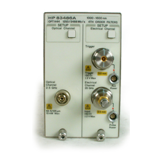
- Page 13 The front panel of the plug-in module has two channel inputs and an external trigger input. The front panel also has a Probe Power connector for HP 54700- series probes, an Aux Power connector for general purpose use, and a key for each channel that displays the softkey menu.
- Page 14 Getting Started The HP 83487A Optical/Electrical Plug-In Module Trigger The external trigger level range for this plug-in module is ±1 V. The trigger source selection depends on the plug-in module location. For example, if the plug-in module is installed in slots 1 and 2, then the trigger source is listed as trigger 2.
-
Page 15: Options And Accessories
Option 0B1 Additional set of user documentation Option 0B0 Deletes the user documentation Option UK6 Measured performance data Option 001 Latest version of operating firmware for the HP 83480A Option 002 Latest version of operating firmware for the HP 54750A Option 011 Diamond HMS-10/HP connector interface... - Page 16 Getting Started Options and Accessories HP 81000SI DIN 47256/4108.6 connector interface HP 81000VI ST connector interface HP 81000WI Biconic...
-
Page 17: Menu And Key Conventions
Getting Started Menu and Key Conventions Menu and Key Conventions The keys labeled Trigger, Disk, and Run are all examples of front-panel keys. Some front-panel keys bring up menus on the right side of the display screen. These menus are called softkey menus. Softkey menus contain functions not available directly by pressing the front- panel keys. -
Page 18: Step 1. Inspect The Shipment
If your shipment is damaged or incomplete, save the packing materials and notify both the shipping carrier and the nearest Hewlett-Packard Sales and Service office. HP will arrange for repair or replacement of damaged or incom- plete shipments without waiting for a settlement from the transportation com- pany. -
Page 19: Step 2. Install The Plug-In Module
You do not need to turn off the mainframe to install or remove the plug-in modules. Note If you wish to use the HP 83487A optical/electrical plug-in module in an HP 54750A dig- itizing oscilloscope, a firmware upgrade must first be installed. Order the HP 83480K communications firmware kit and follow the installation instructions. -
Page 20: Returning The Instrument For Service
HP Instrument Support Center ......(800) 403-0801 If the instrument is still under warranty or is covered by an HP maintenance contract, it will be repaired under the terms of the warranty or contract (the warranty is at the front of this manual). - Page 21 Getting Started Returning the Instrument for Service Preparing the instrument for shipping 1 Write a complete description of the failure and attach it to the instrument. Include any specific performance details related to the problem. The following information should be returned with the instrument. •...
- Page 22 Getting Started Returning the Instrument for Service • The carton must be large enough to allow approximately 7 cm (3 inches) on all sides of the instrument for packing material, and strong enough to accom- modate the weight of the instrument. •...
-
Page 23: Channel Setup Menu
Channel Setup Menu 2-2 Displaying the Channel Setup Menus 2-5 Channel Setup Menu... - Page 24 Channel key is pressed. There are several types of softkeys available. A description of the different softkeys and their functions is provided in the HP 83480A, 54750A User’s Quick Start Guide supplied with the mainframe.
- Page 25 Channel Setup Menu Channel Setup Menu Figure 2-1. Optical Channel Setup menu.
- Page 26 Channel Setup Menu Channel Setup Menu Figure 2-2. Electrical Channel Setup menu.
-
Page 27: Displaying The Channel Setup Menus
Channel Setup Menu Displaying the Channel Setup Menus Displaying the Channel Setup Menus To display the optical Channel Setup menu, press the Optical Channel key located above the optical input connector. To display the electrical Channel Setup menu, press the Electrical Channel key located above the electrical input connector. - Page 28 Channel Setup Menu Display Display The Display softkey turns the channel display off and on. When the channel dis- play is on, a waveform is displayed for that channel, unless the offset is adjusted so the waveform is clipped off the display. The channel number, vertical scaling, and offset are displayed at the bottom left of the waveform area.
- Page 29 The fine mode also works with offset. When an HP 54700-series active probe is connected to the probe power con- nector, the offset control adjusts the external scale factor and offset of the hybrid inside the active probe.
- Page 30 Channel Setup Menu Bandwidth/Wavelength..Bandwidth/Wavelength..You can use the Bandwidth/Wavelength..softkey to change the bandwidth and wavelength settings. Bandwidth This function is available on the electrical channel only. You can use the Bandwidth function to select either the 12.4 GHz or 20 GHz bandwidth.
- Page 31 Channel Setup Menu Channel autoscale Channel autoscale The Channel autoscale softkey provides a convenient and fast method for deter- mining the standard vertical scale setting with the highest resolution that will not clip the waveform. Timebase and trigger settings are not affected. This function is useful in manufacturing environments where the timebase and trigger settings remain constant and only the vertical scale needs to be adjusted for signal level variations in multiple devices under test.
- Page 32 Channel Setup Menu External scale..External scale..The External scale softkey allows you to set up the analyzer to use external opti- cal-to-electrical converters or attenuators. Scaling is automatically adjusted to account for the external device. Key Path Channel, External scale..Atten units The Atten units function lets you select how you want the probe attenuation factor represented.
- Page 33 Channel Setup Menu External scale..Units The Units function lets you select the unit of measure appended to the channel scale, offset, trigger level, and vertical measurement values. For the optical channel these units are Volts or Watts. For the electrical channel the units are Volts, Amperes, Watts, or unknown.
- Page 34 Channel Setup Menu Calibrate Calibrate The Calibrate softkey allows you to null any skew between probes or cables, remove the effects of offsets in the internal O/E converter, recalibrate the responsivity of the O/E converter, and check the present calibration status of the analyzer.
- Page 35 Channel Setup Menu Calibrate Cal status The Cal status function displays a screen similar to Figure 2-3. Channel, Calibrate, Cal Status Key Path Figure 2-3. A typical Cal Status display. This is the current date and time. You can compare this to the last plug-in Current Date module calibration time to see how long it has been since calibration was per- formed.
- Page 36 The analyzer also automatically compensates for any offset the probe may introduce. The CAL signal is inter- nally routed to the probe tip for HP probes. Channel, Calibrate, Calibrate probe Key Path...
-
Page 37: Calibration Overview
Factory Calibrations 3-4 User Calibrations—Optical and Electrical 3-7 Complete Calibration Summary 3-19 Calibration Overview... - Page 38 Proper calibration is critical to measurement accuracy and repeatability. The HP 54750A/83480A and their associated modules and accessories require that both factory and user calibrations be implemented at the recommended inter- vals in order to perform measurements at their published specifications.
- Page 39 To maintain specifications, periodic recalibrations are necessary. We recommend that the plug-in module be calibrated at an HP ser- vice facility every 12 months. Users are encouraged to adjust the calibration cycle based on their particular operating environment or measurement accu- racy needs.
-
Page 40: Factory Calibrations
Measurements Recommended Calibration What is calibrated Softkey Path Affected Interval Mainframe Accuracy and Channels affected: Annually at HP service Utility Calibration continuity of the optical & electrical. All center or if operating Calibrate timescale time base temp has changed and... - Page 41 Factory Calibrations drawing that shows each switch’s function and protected position. Refer to the optional HP 83480A, 54750A Service Guide for more details about the main- frame calibration, and the position of the rear-panel memory protect switches. C A U T I O N To prevent access to the mainframe calibration switch, place a sticker over the access hole to this switch.
- Page 42 The accuracy of all optical channel measurements is dependent on proper O/E calibration. O/E calibrations should be performed annually. Most customers return their optical plug-ins to an authorized HP ser- vice center for this calibration at the same time they are having their main- frames re-calibrated.
-
Page 43: User Calibrations-Optical And Electrical
Calibration Overview User Calibrations—Optical and Electrical User Calibrations—Optical and Electrical The following calibrations can be performed by the user: O/E User Wavelength Calibration Plug-in Module Vertical Calibration Offset Zero Calibration Dark Calibration Probe Calibration Channel Skew External Scale Electrical channels have calibration procedures for: •... - Page 44 Calibration Overview User Calibrations—Optical and Electrical Table 3-2. Optical and Electrical Channel User Calibration Summary Measurements Recommended Calibration What is calibrated Key Path Affected Interval O/E User Wavelength The photodetector Channels affected: Annual re-calibration Optical Channel Setup Calibration responsivity optical. All optical of user defined non- Calibrate channel...
- Page 45 Calibration Overview User Calibrations—Optical and Electrical Table 3-3. Miscellaneous User Calibration Summary Measurements Recommended Calibration What is calibrated Key Path Affected Interval Probe calibration Probe Attenuation Channels affected: Whenever a probe is Electrical Channel Setup electrical. Any connected Calibrate electrical Calibrate probe measurement taken with the probe...
- Page 46 For best results, measure the optical source power with an optical power meter such as the HP 8153A and use precision optical connectors. In addition, proper connector cleaning procedures are essential to obtaining an accurate calibration.
- Page 47 Calibration Overview User Calibrations—Optical and Electrical Plug-in Module Vertical Calibration The plug-in module vertical calibration is for both optical and electrical mea- surements. It allows the instrument to establish the calibration factors for a specific plug-in when the plug-in is installed in the mainframe. The plug-in cal- ibration factors are valid only for the specific mainframe slot in which it was calibrated.
- Page 48 If you are prompted to connect the calibrator output to the electrical channel during an optical vertical calibration, then the factory O/E calibration has been lost. The module must then be returned to HP for calibration. Offset Zero Calibration The offset zero calibration performs a quick offset calibration on the optical channel for optical measurements.
- Page 49 Calibration Overview User Calibrations—Optical and Electrical Figure 3-3. Offset Zero Calibration Dark Calibration The dark calibration is for optical measurements, or electrical measurements if an external O/E is being used. This calibration measures the optical channel offset signal when there isn’t any light present and then uses this information in performing extinction ratio measurements.
- Page 50 Calibration Overview User Calibrations—Optical and Electrical To initiate a dark calibration 1 Press the Display key. Press the Color grade softkey, and set its setting to on. Color grade must be enabled to perform an extinction ratio measurement and a dark calibration. In addition, the dark level (amplitude when there is no signal present) must be on the screen to perform a dark calibration.
- Page 51 Probe Calibration Probe calibration applies to electrical measurements only. For active probes such as the HP 54701A, which the instrument can identify through the probe power connector, the instrument automatically adjusts the channel vertical scale factors to the probe’s nominal attenuation, even if a probe calibration is not performed.
- Page 52 You can use the probe calibration to calibrate any network, including probes or cable assemblies. The instrument calibrates the voltage at the tip of the probe or the cable input. To calibrate an HP identifiable probe 1 Press the plug-in module’s front-panel-channel SETUP key. 2 Press Calibrate and then Calibrate Probe.
- Page 53 Calibration Overview User Calibrations—Optical and Electrical Figure 3-5. Electrical Channel Calibrate Menu To calibrate other devices The information in this section applies to both optical and electrical measure- ments. Since the mainframe’s CAL signal is a voltage source, it cannot be used to calibrate to the probe tip when the units are set to Ampere, Watt, or Unknown.
- Page 54 Calibration Overview User Calibrations—Optical and Electrical External Scale Both optical and electrical channels have an External scale setting which allows the user to enter in an offset value to compensate for gains or losses not associated with the device under test. This feature is useful for adjusting out the effects of devices such as test fixtures and attenuators so that the reading on the display gives the measurement value associated with only the actual device under test.
-
Page 55: Complete Calibration Summary
Recommended Calibration What is calibrated Key Path Affected Interval Mainframe Calibration Accuracy and Channels affected: Annually at HP service Utility continuity of the optical & electrical. All center or if operating Calibrate timescale time base temp has changed and Calibrate frame measurements such remains 5°C or more... - Page 56 Calibration Overview Complete Calibration Summary Table 3-4. Complete Calibration Summary (2 of 3) Measurements Recommended Calibration What is calibrated Key Path Affected Interval Offset Zero Calibration Vertical offset is Channels affected: Perform a plug-in Optical Channel Setup calibrated for the optical.
- Page 57 Calibration Overview Complete Calibration Summary Table 3-4. Complete Calibration Summary (3 of 3) Measurements Recommended Calibration What is calibrated Key Path Affected Interval External Scale Compensates for gain Channels affected: Whenever using Channel Setup or loss associated optical & electrical. external devices External Scale with external devices...
- Page 58 Calibration Overview Complete Calibration Summary 3-22...
- Page 59 Specifications 4-3 Characteristics 4-8 Declaration of Conformity 4-9 Specifications and Regulatory Information...
- Page 60 Specifications apply over the temperature range +15°C to +35°C (unless otherwise noted) after the instrument’s temperature has been stabilized after 60 minutes of continuous operation. Refer to the HP 54701A Active Probe Service Guide for complete probe speci- fications. Specifications Specifications described warranted performance.
- Page 61 Specifications and Regulatory Information Specifications Specifications Table 4-1. HP 83487A Electrical Channel Vertical Specifications Bandwidth (–3 dB) dc to 12.4 GHz or 20 GHz, user selectable dc Accuracy—single voltage marker ± 12.4 GHz 0.4% of full scale ± ± 2 mV 1.5% (reading –...
- Page 62 Specifications and Regulatory Information Specifications Table 4-1. HP 83487A Electrical Channel Vertical Specifications (Continued) ≤ 20 GHz 1 mV (0.5 mV typical) Scale Factor (full scale is eight divisions) Minimum 1 mV/div Maximum 100 mV/div ± dc Offset Range 500 mV Ω...
- Page 63 Specifications and Regulatory Information Specifications Table 4-2. HP 83487A Optical Channel Vertical Specifications Bandwidth (–3 dB) dc to 2.85 GHz (dc to 3.0 GHz characteristic) Maximum Specified Peak Input Power Continuous Wave 0.6 mW (–2.2 dBm) Modulated 0.4 mW (–4 dBm) ±...
-
Page 64: Specifications And Regulatory Information Specifications
Specifications and Regulatory Information Specifications Table 4-2. HP 83487A Optical Channel Vertical Specifications (Continued) µ µ Specified operating range (average power) –30 dBm to –2.2 dBm (1 W to 500 µ Maximum peak power input (typical) (4000 W (6 dBm) typical) °... - Page 65 Specifications and Regulatory Information Specifications Table 4-4. Power Requirements Supplied by mainframe. Table 4-5. Weight approximately 1.2 kg (2.6 lb.) Shipping approximately 2.1 kg (4.6 lb.)
-
Page 66: Characteristics
Specifications and Regulatory Information Characteristics Characteristics The following characteristics are typical for the HP 83487A optical/electrical plug-in module. Refer to the HP 54701A Active Probe Service Guide for complete probe characteristics. Table 4-6. Trigger Input Characteristics for Electrical and Optical Channels Ω... -
Page 67: Declaration Of Conformity
Specifications and Regulatory Information Declaration of Conformity Declaration of Conformity... - Page 68 Specifications and Regulatory Information Declaration of Conformity 4-10...
-
Page 69: Reference
In Case of Difficulty 5-2 Measuring High Power Waveforms 5-6 Error Messages 5-10 Electrostatic Discharge Information 5-12 Cleaning Connections for Accurate Measurements 5-14 Hewlett-Packard Sales and Service Offices 5-25 Reference... -
Page 70: In Case Of Difficulty
This chapter also includes information regarding measuring high power wave- forms with the HP 83480/HP 83487A, electrostatic discharge (ESD), proce- dures for cleaning both optical and electrical connections, and a list of HP Sales and Service Offices. - Page 71 • Is the rear-panel line switch set to on? • Will the mainframe power up without the plug-in module installed? If the mainframe still does not power up, refer to the optional HP 83480A, 54750A Service Guide or return the mainframe to a qualified service depart-...
- Page 72 Reference In Case of Difficulty If the plug-in does not operate 1 Make the following checks: • Is the plug-in module firmly seated in the mainframe slot? • Are the knurled screws at the bottom of the plug-in module finger-tight? •...
- Page 73 3.5 inch diskette. To load new firmware, follow the instructions provided with this diskette. If you do not have the optional diskette, contact your local HP Sales and Service Office (refer to “Hewlett- Packard Sales and Service Offices” on page 5-25).
-
Page 74: Measuring High Power Waveforms
100% overshoot is that the average power should not exceed 100 µW (–10 dBm). 1. While the HP 83487A module is specified to receive a continuous wave peak power of up to µ W (–2.2 dBm), high frequency ringing in a modulated signal can cause compression at µ... - Page 75 Average power can be measured directly using the internal power meter of the HP 83487A, by pressing: blue Shift key, More meas key on the numeric keypad and then the Avg Power softkey. Then select the data to be reported in dBm.
- Page 76 In order to find out if your device under test may be exceeding the input power requirements for the HP 83487A, first measure the average power with the internal power meter, and then measure the peak power on the eye dia- gram.
- Page 77 Using the fixed 5 dB attenuator The HP 83487A is shipped with a nominal 5 dB attenuator (±1.5 dB), which will provide correct attenuation for most signals up to –5 dBm average power (the current allowable standard). Follow the procedure outlined above to use this attenuator and enter in the correct offset value.
-
Page 78: Error Messages
If the suggestions do not eliminate the error message, then additional troubleshooting is required that is beyond the scope of this book. Refer to the HP 83480A, 54750A Service Guide for additional troubleshooting information. - Page 79 2 Verify the plug-in module is firmly seated in the mainframe slot. 3 Verify the knurled screws at the bottom of the plug-in module are finger tight. 4 The standard HP 54750A mainframe does not accept the HP 83487A optical/ electrical plug-in module optical/electrical plug-in module. To use the module, a firmware upgrade must first be installed.
-
Page 80: Electrostatic Discharge Information
Reference Electrostatic Discharge Information Electrostatic Discharge Information Electrostatic discharge (ESD) can damage or destroy electronic components. All work on electronic assemblies should be performed at a static-safe work station. The following figure shows an example of a static-safe work station using two types of ESD protection: •... - Page 81 • Personnel should be grounded with a resistor-isolated wrist strap before re- moving any assembly from the unit. • Be sure all instruments are properly earth-grounded to prevent a buildup of static charge. Table 5-2. Static-Safe Accessories HP Part Number Description × × 9300-0797 Set includes: 3M static control mat 0.6 m...
-
Page 82: Cleaning Connections For Accurate Measurements
Reference Cleaning Connections for Accurate Measurements Cleaning Connections for Accurate Measurements Today, advances in measurement capabilities make connectors and connec- tion techniques more important than ever. Damage to the connectors on cali- bration and verification devices, test ports, cables, and other devices can degrade measurement accuracy and damage instruments. - Page 83 HP instruments typically use a connector such as the Diamond HMS-10, which has concentric tolerances within a few tenths of a micron. HP then uses a spe- cial universal adapter, which allows other cable types to mate with this preci- sion connector.
- Page 84 0.2 µm. This process, plus the keyed axis, allows very precise core-to-core alignments. This connector is found on most HP lightwave instruments. 5-16...
- Page 85 Reference Cleaning Connections for Accurate Measurements The soft core, while allowing precise centering, is also the chief liability of the connector. The soft material is easily damaged. Care must be taken to mini- mize excessive scratching and wear. While minor wear is not a problem if the glass face is not affected, scratches or grit can cause the glass fiber to move out of alignment.
- Page 86 Reference Cleaning Connections for Accurate Measurements Figure 5-4. Clean, problem-free fiber end and ferrule. Figure 5-5. Dirty fiber end and ferrule from poor cleaning. Figure 5-6. Damage from improper cleaning. 5-18...
- Page 87 Reference Cleaning Connections for Accurate Measurements While these often work well on first insertion, they are great dirt magnets. The oil or gel grabs and holds grit that is then ground into the end of the fiber. Also, some early gels were designed for use with the FC, non-contacting con- nectors, using small glass spheres.
- Page 88 Reference Cleaning Connections for Accurate Measurements Measuring insertion loss and return loss Consistent measurements with your lightwave equipment are a good indica- tion that you have good connections. Since return loss and insertion loss are key factors in determining optical connector performance they can be used to determine connector degradation.
- Page 89 The procedures in this section provide the proper steps for cleaning fiber- optic cables and HP universal adapters. The initial cleaning, using the alcohol as a solvent, gently removes any grit and oil. If a caked-on layer of material is...
- Page 90 Reference Cleaning Connections for Accurate Measurements Table 5-4. Dust Caps Provided with Lightwave Instruments Item HP Part Number ST dust cap 5040-9366 To clean a non-lensed connector C A U T I O N Do not use any type of foam swab to clean optical fiber ends. Foam swabs can leave filmy deposits on fiber ends that can degrade performance.
- Page 91 Cleaning Connections for Accurate Measurements To clean an adapter The fiber-optic input and output connectors on many HP instruments employ a universal adapter such as those shown in the following picture. These adapt- ers allow you to connect the instrument to different types of fiber-optic cables.
- Page 92 Caring for electrical connections The following list includes the basic principles of microwave connector care. For more information on microwave connectors and connector care, consult the Hewlett-Packard Microwave Connector Care Manual, HP part number 08510-90064. Handling and Storage • Keep connectors clean •...
-
Page 93: Hewlett-Packard Sales And Service Offices
Reference Hewlett-Packard Sales and Service Offices Hewlett-Packard Sales and Service Offices Before returning an instrument for service, call the HP Instrument Support Center at (800) 403-0801. Hewlett-Packard Sales and Service Offices (1 of 2) U.S. FIELD OPERATIONS Headquarters California, Northern... - Page 94 Reference Hewlett-Packard Sales and Service Offices Hewlett-Packard Sales and Service Offices (2 of 2) INTERCON FIELD OPERATIONS Headquarters Australia Canada Hewlett-Packard Company Hewlett-Packard Australia Ltd. Hewlett-Packard Ltd. 3495 Deer Creek Rd. 31-41 Joseph Street 17500 South Service Road Palo Alto, California 94304-1316 Blackburn, Victoria 3130 Trans-Canada Highway (415) 857-5027...
- Page 95 Index fiber-optic connections, 5-14, 5-22 non-lensed connectors, 5-22 accessories, compressed dust remover, 5-21 active probe, connector Atten units softkey, 2-10 care, 5-14 attenuation care manual, 5-24 range, 2-10 cotton swabs, 5-21 Attenuation softkey, 2-10 Current Date message, 2-13 attenuator, scaling, 2-10, Current Frame Delta Temp, 2-13 automatic measurement,...
- Page 96 Index plug-in message, 2-14 plug-in module high power signals, features, horizontal waveform, 2-12 front panel, HP offices, 5-25 serial number, 1-10 plug-in module vertical calibration, 3-11 power level, IEC Publication 1010, maximum input, input probe connector, 5-14 attenuation, 2-10, 2-14...
- Page 97 Index external, level, 2-11 source, troubleshooting, Units softkey, 2-7, 2-11 user calibrations, vertical measurement, 2-11 scale, 2-6–2-9 waveform, voltage measurement, 2-10 probe, 2-14 voltage probe calibration, 3-15 wattage measurement, 2-10 waveform display, horizontal, 2-12 waveforms high power, Wavelength key, wavelength settings, Index-3...
- Page 98 Index Index-4...
Need help?
Do you have a question about the 83487A and is the answer not in the manual?
Questions and answers