Sign In
Upload
Download
Table of Contents
Contents
Add to my manuals
Delete from my manuals
Share
URL of this page:
HTML Link:
Bookmark this page
Add
Manual will be automatically added to "My Manuals"
Print this page
×
Bookmark added
×
Added to my manuals
Manuals
Brands
Vatech Manuals
Medical Equipment
Green 16
Installation manual
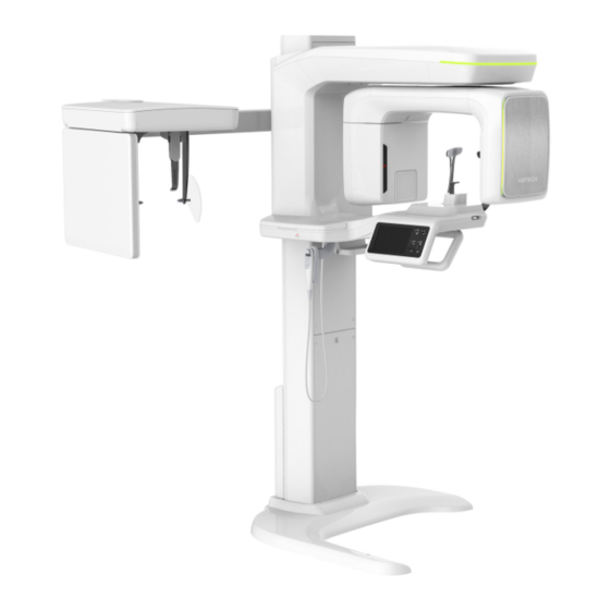
Vatech Green 16 Installation Manual
Hide thumbs
1
2
3
4
Table Of Contents
5
6
7
8
9
10
11
12
13
14
15
16
17
18
19
20
21
22
23
24
25
26
27
28
29
30
31
32
33
34
35
36
37
38
39
40
41
42
43
44
45
46
47
48
49
50
51
52
53
54
55
56
57
58
59
60
61
62
63
64
65
66
67
68
69
70
71
72
73
74
75
76
77
78
79
80
81
82
83
84
85
86
87
88
89
90
91
92
93
94
95
96
97
98
99
100
101
102
103
104
105
106
107
108
109
110
111
112
113
114
115
116
117
118
119
120
121
122
123
124
125
126
127
128
129
130
131
132
133
134
135
136
137
138
139
140
141
142
143
144
145
146
147
148
149
150
151
152
153
154
155
156
157
158
159
160
161
162
page
of
162
Go
/
162
Contents
Table of Contents
Bookmarks
Table of Contents
Table of Contents
Introduction
Customer's Responsibility
Manufacturer's Liability
Conventions in this Manual
Marks and Symbols
Standards and Regulations
Choosing an Installation Site
Room Requirements
Specifications for Electrical Installation
Electrical Requirement
Environmental Specifications
Exposure Switch Installation Options
Installation Versions
Installing the Warning Lamp and Door Interlock Switch
Installing the Emergency Stop Switch
Before Installing the System
Required Tools
Checking the Shockwatch and Tiltwatch Indicators
Unpacking Boxes
Checking the Parts
Installing the Equipment: Base Stand (Optional)
Assembling the Base and Main Units
Installing the CEPH Unit (Optional)
Installing the Wall and Column Brackets
Fixing the Base (Optional)
Connecting the Cables to the Equipment
Removing the Transportation Safety Bolts
Leveling the Equipment
Tightening the Bolts
Installing the Equipment: Wall Mount
Installing the Equipment
Installing the CEPH Unit (Optional)
Installing the Wall and Column Brackets
Connecting the Cables to the Equipment
Removing the Transportation Safety Bolts
Leveling the Equipment
Tightening the Bolts
Completing Miscellaneous Works
Assembling Various Covers
Assembling the Temple Supports and the Chinrest
Installing the Switch Holders
Setting up PC
Direct Connection Diagram
The Recommended PC Requirements
Disabling Windows Defender
Installing the Internal Peripherals
Connecting the Cables to PC
Setting up PC Environment Variables
Before Beginning
Turning off the Firewall
Setting up the Power Management Options
Turning off the User Account Control
Setting Folder Exclusions with Anti-Virus Software
Installing Software
Before Beginning
Software Installation Flow
Installing the Image Viewer Program
Installing the Install-Package
Configuring User Information
Disabling the Packing Mode
Selecting an Announcement Mode (Optional)
10. Technical Specifications
Mechanical Specifications
Electrical Specifications
Environmental Specifications
Installing the Warning Lamp and Door Interlock Switch
Installing the Emergency Stop Switch
Limiting the Column Height
Connecting the
Party Exposure Switch (Optional)
Checking PC BIOS Settings
Installation Checklist
Advertisement
Quick Links
1
Table of Contents
2
10. Technical Specifications
Download this manual
Installation Manual
Model : PHT-65LHS
Version : 1.49
English
Full Version
Table of
Contents
Previous
Page
Next
Page
1
2
3
4
5
Advertisement
Table of Contents
Need help?
Do you have a question about the Green 16 and is the answer not in the manual?
Ask a question
Questions and answers
Related Manuals for Vatech Green 16
Medical Equipment Vatech Green 18 Installation Manual
(162 pages)
Medical Equipment Vatech GREEN SMART User Manual
(200 pages)
Medical Equipment Vatech Green 21 PCT-90LH User Manual
(128 pages)
Medical Equipment Vatech Pax-i PCH-2500 Installation Manual
(200 pages)
Medical Equipment VATECH EzSensor Classic Installation & User Manual
(69 pages)
Medical Equipment Vatech Smart Plus PHT-35LHS Technical Manual
(190 pages)
Medical Equipment Vatech A9 User Manual
(196 pages)
Medical Equipment Vatech PaX-Primo Installation Manual
(72 pages)
Medical Equipment VATECH EzSensor Installation & User Manual
Digital x-ray intraoral sensor system latest cmos technology usb2.0 (50 pages)
Medical Equipment VATECH PaX-i3D User Manual
Extra-oral imaging system (167 pages)
Medical Equipment Vatech Premium PAX-i3D User Manual
(204 pages)
Medical Equipment VATECH PAX-I User Manual
(137 pages)
Medical Equipment Vatech EzRay Air Wall User Manual
(193 pages)
Medical Equipment Vatech EzRay Chair User Manual
(86 pages)
Medical Equipment Vatech PaX-i Plus PCH-30CS User Manual
(249 pages)
Medical Equipment Vatech PaX-i3D Smart User Manual
(157 pages)
This manual is also suitable for:
Green 18
Pht-65lhs
Table of Contents
Print
Rename the bookmark
Delete bookmark?
Delete from my manuals?
Login
Sign In
OR
Sign in with Facebook
Sign in with Google
Upload manual
Upload from disk
Upload from URL


Need help?
Do you have a question about the Green 16 and is the answer not in the manual?
Questions and answers