Table of Contents
Advertisement
Advertisement
Table of Contents

Related Manuals for Vatech Green 21 PCT-90LH


Summary of Contents for Vatech Green 21 PCT-90LH
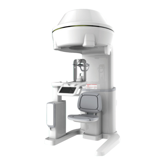
- Page 1 User Manual Model : PCT-90LH Version : 1.49 English Full version...
- Page 3 All brand names and logos used in this manual are copyrighted. For further information not covered in this manual or in the accompanying documentation, please contact us with any method listed below: Manufacturer: VATECH Co., Ltd. Telephone: +82-1588-9510 E-Mail: gcs@vatech.co.kr Manual name: Green 21 (Model: PCT-90LH) Installation Manual Version: 1.49...
- Page 4 Conventions Used in this Manual Conventions Used in this Manual The following symbols are used throughout this manual. Make sure that you fully understand each symbol and follow the instructions accompanied. To prevent physical injury and/or damage to the equipment, please observe all warnings and safety information included in this document.
- Page 5 Conventions Used in this Manual This Page Left Blank Intentionally Green21 (Model: PCT-90LH) Installation Manual...
- Page 6 Important Precautions Important Precautions To avoid improperly balanced equipment, install the device on a flat surface to maintain stability. If the equipment is not stable, property damage and/or personal injury may occur. DO NOT push or pull the equipment. Make sure the X-ray align is correct Equipment should only be installed by an authorized technician, complying with proper installation procedures.
- Page 7 5. Do not connect any items or equipment to this system which are not part of the system: IEC60601-1-1 (3rd edition: 2005). 6. Any equipment not approved by VATECH must comply with the applicable standards: IEC 60950-1 (2nd edition: 2005) for IT equipment (Ex: PC) and IEC 60601-1 (3rd edition: 2005) for medical electrical equipment.
- Page 8 Important Precautions Never touch or hold the following areas while moving, installing, or operating the equipment. 2) Handle Frame, Touch Screen, and 1) Rotating Unit Column Unit Installation Site 1. The PC monitor, emergency cut off switch and X-Ray exposure switch should be installed near the operator so that he or she can manage them simultaneously in an emergency.
- Page 9 Important Precautions Before installation, unload the Rotating Unit and place it on the floor as shown in the following figure. To install the equipment safely, at least three installers are required. Green21 (Model: PCT-90LH) Installation Manual...
- Page 10 Important Precautions Locations of the Main Power and the Emergency Stop Switches <Main Power Switch> <Emergency Stop Switch> viii Green21 (Model: PCT-90LH) Installation Manual...
-
Page 11: Table Of Contents
Table of Contents Table of Contents Notice Conventions Used in this Manual Important Precautions Table of Contents Introduction Manufacturer’s Liability ............... 3 Customer’s Responsibility ..............3 Marks and Symbols ................4 Standards and Regulations ..............6 Choosing an Installation Site Room Requirements ................ - Page 12 Table of Contents Setting Chinrest & Column Limit ............ 44 4.10 Check X-ray align (4% Cut) .............. 46 4.11 Air Calibration ................... 54 Setting up PC Direct Connection Diagram ............... 57 Recommended PC Requirements ............58 Recommended UPS Specification (Option) ........59 Installing the Grabber Card...............
- Page 13 Table of Contents This Page Left Blank Intentionally Green21 (Model: PCT-90LH) Installation Manual...
- Page 14 0. Table of Contents This Page Left Blank Intentionally Green21 (Model: PCT-90LH) Installation Manual...
-
Page 15: Introduction
Introduction Introduction Manufacturer’s Liability As the manufacturer, VATECH assumes liability for the safe and reliable installation and operation of this equipment only when: Equipment installation, including software installation, was conducted by an authorized agent in accordance with this installation manual. -
Page 16: Marks And Symbols
1. Introduction Marks and Symbols Symbols Description Location Alternate current Dangerous voltage Power board Protective earth (Ground) Power board Off (power: disconnected to the Main Main Power Switch Power Switch) On (power: connected to the Main Main Power Switch Power Switch) Type B Applied Equipment (IEC60601-1: Degree of protection Label... - Page 17 1. Introduction Symbols Description Location Indicates that electrical and electronic equipment must not be disposed of as Label unsorted municipal waste and must be collected separately. MCU board Warns ESD hazard. / Board package Indicates that this equipment is classified as a CLASS 1 LASER Label PRODUCT in accordance with IEC 60825-1 ED.3 regulations.
-
Page 18: Standards And Regulations
1. Introduction Standards and Regulations Standards Green 21 (Model: PCT-90LH) was designed and developed to comply with the following international standards and regulations: MEDICAL EQUIPMENT WITH RESPECT TO ELECTRICAL SHOCK, FIRE AND MECHANICAL HAZARDS ONLY IN ACCORDANCE WITH UL 60601-1, CAN/CSA-C22.2 No.60.1 This is Class IIb equipment and obtained CE marking in April 2007 for regulations compliance in accordance with the revised European Union’s MDD (Medical Devices... -
Page 19: Choosing An Installation Site
2. Choosing an Installation Site Choosing an Installation Site Room Requirements The location of this equipment should allow for high visibility of the patient by the operator and the operator should be as about the patient as possible. This equipment should not be installed on thick carpets for stability reasons. - Page 20 2. Choosing an Installation Site Ceiling Height: ≥ 2,500mm/98” Dimension (mm/inch) 2,500mm(L) x 2,000mm(W) x 2,500mm(H) / 98”(L) x 79”(W) x 98”(H) If the ceiling height is less than 2,285 mm (= max. height of the Column Unit + 100 mm), refer to ‘Appendix B. Limiting the Column Height’...
-
Page 21: Electrical Requirements
2. Choosing an Installation Site Electrical Requirements This equipment must be connected to a grounded outlet to fulfill the safety provisions specified in IEC 60364: the 2nd edition (2006). It is mandatory that both PC and equipment use the same power line if connected to an MPSO. - Page 22 The user operates the exposure switch outside of the X-ray room. The exposure switch holder is mounted on the wall. The 3rd party exposure switch (not VATECH’s) is used on demand of the customers. For this scenario, follow the procedures as described below.
-
Page 23: Before The Installation
3. Before the Installation Before the Installation Labor To install the equipment safely, at least three installers are required. Required Tools The following tools are required to install the equipment. Item Figure Size Wrench set 1.5 mm-10 mm/0.05-0.4” Monkeywrench 10” Ratchet wrench Tips:3mm-8mm/0.12-0.3”... - Page 24 3. Before the Installation Item Figure Size Hammer Multi-meter Hammer drill Cutting pliers Green21 (Model: PCT-90LH) Installation Manual...
-
Page 25: Unpacking The Boxes
Check the packaging for signs of damage visually before opening the package. If it appears damaged, do not open the package, and immediately contact the shipping company, agent or VATECH. Wear the ant-static or general-purpose gloves. Package Size The package sizes have been measured including the palettes. -
Page 26: Checking The Parts
3. Before the Installation Checking the Parts Base Packing Item Qty. Comment Confirmed Base Assay YES □ NO □ Handle Frame YES □ NO □ Chair YES □ NO □ PC Box Option YES □ NO □ Accessory Box YES □ NO □ Monitor Option YES □... - Page 27 3. Before the Installation 3.5.1 Location Layout of the Parts and Accessories Green21 (Model: PCT-90LH) Installation Manual...
- Page 28 3. Before the Installation 3.5.2 Parts and Accessories List Item Specification Figure Qty. Confirmed User Manual YES□ NO□ Installation YES□ NO□ Manual Easy Dent or Manuals EzDent-I YES□ NO□ Manual Ez3D plus or Ez3D-I YES□ NO□ Manual Wheelchair Height Limit YES□...
- Page 29 3. Before the Installation Item Specification Figure Qty. Confirmed Chinrest Up/Down Chinrest Switch, Up/Down YES□ NO□ Chinrest Switch Up/Down Switch Holder Double Sided YES□ NO□ Sticker Flat Head Bolt M3 x 8 YES□ NO□ Anti-static YES□ NO□ gloves Chin Block YES□...
- Page 30 3. Before the Installation Item Specification Figure Qty. Confirmed Headrest YES□ NO□ Cradle Blank Blank Silicon Cap YES□ NO□ Base Cap YES□ NO□ Vertical Cap YES□ NO□ Wrench Bolt M3 x 6 YES□ NO□ Cable Tie L=100mm YES□ NO□ IFG Card (or) YES□...
- Page 31 3. Before the Installation Item Specification Figure Qty. Confirmed M10 x 40 w/spring YES□ NO□ washer Wrench Bolt M10 Nut YES□ NO□ Wrench Bolt M10 x 60 YES□ NO□ M10 x 40 Wrench Bolt w/spring and YES□ NO□ flat washer M10 x 30 Wrench Bolt w/spring...
- Page 32 3. Before the Installation This Page Left Blank Intentionally Green21 (Model: PCT-90LH) Installation Manual...
-
Page 33: Installation Procedures
4. Installation Procedures Installation Procedures Installing the Column Unit Put the Column Unit on the floor. Figure 4-1. Placement of the Column Unit Remove the Transfer Handle from the Column Unit. Transfer Handle Figure 4-2. Removing the Transfer Handle Green21 (Model: PCT-90LH) Installation Manual... - Page 34 4. Installation Procedures Put two wrench bolts into the holes on the bottom of the Column Unit. Part No.: No.24 Wrench Bolt Size: M10 x 60 Qty.: 2 EA Figure 4-3. Putting two wrench bolts into the holes Put the bolts into the holes until about 35mm is left outside.
- Page 35 4. Installation Procedures Hold the Base Unit to keep it from falling. The rear cable may be pushed when assembling the base unit. Use a cable tie at the rear to tie it up, and work around the cable to prevent it from being pushed. When connecting the base unit, the base unit may hang on the bundled cable exposed in the column.
- Page 36 4. Installation Procedures Figure 4-5. Putting the wrench bolts and tightening them Hold the Upper Handle and stand the equipment up vertically. Upper Handle Figure 4-6. Standing the equipment up vertically Green21 (Model: PCT-90LH) Installation Manual...
- Page 37 4. Installation Procedures Unscrew three bolts on the rear side and remove the bracket. Bracket Figure 4-7. Removing the bracket Unscrew the bolts on the left and right sides and remove the Upper Handle. Upper Handle When removing the shrink wrap first and remove the handlebar bolt, the bolt can be accidentally dropped and get into the column.
- Page 38 4. Installation Procedures Unscrew the transfer screws and labels shown in the following figure since they have been tightened only for transfer. Figure 4-8. Removing the transfer screws and labels Figure 4-9. After removal of the transfer screws DO NOT perform the next step unless the screws have been removed.
-
Page 39: Installing The Rotating Unit
4. Installation Procedures Installing the Rotating Unit Assemble the Rotating Unit with the Column Unit as shown below. At least three installers are required for this step. Figure 4-10. Assembling the Rotating Unit with the Column Unit Tighten five bolts with ten nuts as shown below. Part No.: 23 w/spring and flat Wrench Bolt... - Page 40 4. Installation Procedures Remove the Transfer Handle from the Rotating Unit. Figure 4-12. Removing the transfer handle Connect the cables to the Rotating Unit referring to Section 4.4.1. Unscrew two bolts in the Rotating Unit as shown below. Figure 4-13. Unscrewing two bolts Green21 (Model: PCT-90LH) Installation Manual...
- Page 41 4. Installation Procedures Remove the transfer screws with labels, and spacers. Check if they have been correctly removed as shown below. Figure 4-14. Checking removed screws with labels, and spacers DO NOT perform the next step unless the screws with labels and spacers have been removed.
-
Page 42: Installing The Handle Frame And Chair
4. Installation Procedures Installing the Handle Frame and Chair 4.3.1 Installing the Handle Frame Handle frame knob locking is released so that the damage will be reduced, even if there is an impact outside the packing box. Put the Handle Frame into the Base Unit and tighten two bolts on the front side as shown in the following figures. - Page 43 4. Installation Procedures Tighten two bolts on the rear side as shown in the following figures. Part No.: 26 w/spring Wrench Bolt Size: M10 x 30 Qty.: 2 ea Figure 4-16. Tightening two bolts on the rear side Connect the cables to the rear side of the Handle Frame referring to Section 0.
- Page 44 4. Installation Procedures 4.3.2 Installing the Chair Turn on the system and raise the Column Unit (with the Rotating Unit) to assemble the Chair. Assemble the Chair with the Column Unit as shown below. Figure 4-17. Assembling the Chair Green21 (Model: PCT-90LH) Installation Manual...
-
Page 45: Connecting The Cables
4. Installation Procedures Connecting the Cables 4.4.1 Connecting the Cables to the Rotating Unit Check if there are six cables before performing the connection. Figure 4-18. Checking cables USB is not connected at the time of manufacture. Connect USB when installing. Green21 (Model: PCT-90LH) Installation Manual... - Page 46 4. Installation Procedures Connect the vertical LED cable, Optic cable, and power cables including USB cable to the top of the Rotating Unit as shown below. Refer to the Cable Information in Table 4-1. Figure 4-19. Connecting the cables to the Rotating Unit After connecting the Cable No.
- Page 47 4. Installation Procedures Table 4-1. Cable Information Cable No. Description Qty. H001747A USB CABLE 4 H000099A OPTIC CABLE 16 H001717A VERTICAL LED CABLE 1 H001705A GENERATOR INVERTER POWER CABLE 2 H001715A ROTATOR POWER & SIGNAL CABLE 1 4.4.2 Connecting the cables to the Handle Frame Connect the cables to the rear side of the Handle Frame.
-
Page 48: Leveling The Equipment
4. Installation Procedures Leveling the Equipment Place the spirit level for leveling the front/rear on top of the Rotating Unit as shown below. Figure 4-21. Leveling the front/rear Adjust the level foot on the Base Unit until the bubble in the middle of the spirit level is centered. - Page 49 4. Installation Procedures For leveling the left/right, place the spirit level as shown below. Figure 4-22. Leveling the left/right Repeat Step 2). Green21 (Model: PCT-90LH) Installation Manual...
-
Page 50: Assembling Covers
4. Installation Procedures Assembling Covers After assembling covers by tightening screws, cover the holes with silicon caps. Assemble the cover on the rear side of the Handle Frame by tightening two screws. Part No.: 27 Truss Screw Size: M4 x 8 Qty.: 2 ea Figure 4-23. - Page 51 4. Installation Procedures Assemble the covers on the Base Unit by tightening five wrench bolts. Make sure to use wrench bolts for assembling the Base Unit’s covers. Part No.: 29 Wrench Bolt Size: M4 x 12 Qty.: 5 ea Figure 4-24.
- Page 52 4. Installation Procedures For assembling the covers on the Rotating Unit, attach the covers on the left/right bottom and rear sides. Tighten four truss screws on the bottom right side first as below and repeat the same procedure for the bottom left side. Part No.: 27 Truss Screw Size: M4 x 8...
- Page 53 4. Installation Procedures Finally, assemble the rear cover of the Rotating Unit by tightening seven screws. Part No.: 30 Pan Head Screw Size: M4 x 8 Qty.: 7 ea Figure 4-26. Assembling the rear cover of the Rotating Unit Green21 (Model: PCT-90LH) Installation Manual...
- Page 54 4. Installation Procedures Assemble the rear cover of the Column Unit and tighten four screws on the left and right sides of the cover. Part No.: 27 Truss Screw Size: M4 x 8 Qty.: 4 ea <Assemble the rear cover> <Left side of the cover>...
-
Page 55: Aligning The Chinrest
4. Installation Procedures Aligning the Chinrest The original position setting of the Chinrest may be changed while transferring the equipment, so aligning the Chinrest is required. Check if the system is turned on, and adjust the Chinrest checking the image. Checking Chinrest Block Alignment Check that the position of the chinrest block is out of the criteria value. -
Page 56: Setting Chinrest & Column Limit
4. Installation Procedures Setting Chinrest & Column Limit Make sure to remove the inner Carbon Cover of the Rotating Unit before conducting this section. * Disassembly of the inner Carbon Cover. Check the height of the chinrest block. Make sure that the position of the chinrest ... - Page 57 4. Installation Procedures * If CSET_1 value is greater than CRDL value, input CRDL value as CSET_1 value. (ex: CSET_1 value is 43 and CRDL value is 39, enter [SPM_CRDL_43].) Up limit setting Place the Column at the topmost (using the LCD button.) Column Topmost limit setting: [SPM_CLUL] iii.
-
Page 58: Check X-Ray Align (4% Cut)
4. Installation Procedures 4.10 Check X-ray align (4% Cut) Make sure to remove the inner Carbon Cover of the Rotating Unit before conducting this section. * Disassembly of the inner Carbon Cover. Make sure the X-ray align is correct. The criteria for left, right, top and bottom are ... - Page 59 4. Installation Procedures 4.10.1 How to Modify Copy the Collimator.ini file and back up to C:\VCaptureSW\SettingFiles folder. Remove Carbon case and chair. When performing the collimator correction, wait for 10 minutes after performing one CT sequence shot and then take another shot.
- Page 60 4. Installation Procedures Before inputting speed correction value, [SPM_CLV?] & [SPM_CLV?] Check the value set by the command first and add [SPM_CLVC_xxxx] & [SPM_CRVC_xxxx] by adding the calculated value to the set value. ex) Check setting value: [SPM_CLV?] 0006(=+6) Calculate input values: +11 (calculated value) +6 (set value) = 17 Input [SPM_CLVC_0017] If the calculated value is negative, enter 1 for the first digit.
- Page 61 4. Installation Procedures Initial Collimator position correction (start position compensation between sensor and collimator) After running C:\VCaptureSW\Util\EzEval_Phantom\EzEval.exe, open the previously backed up PROJ folder and check the collimator invasion area on the left and right side, respectively. * Backup folder: PROJ_4%cut * Backup folder: PROJ_Velo Left side Right side...
- Page 62 4. Installation Procedures Before inputting position correction value, [SPM_CLI?] & [SPM_CRI?] Check the value set by the command first and add [SPM_CLIC_xxxx] & [SPM_CRIC_xxxx] by adding the calculated value to the set value. ex) Check setting value: [SPM_CLI?] 0006(=+6) Calculation of input values: +39 (calculated value) + +6 (set value) = +45 Input [SPM_CLIC_0045]...
- Page 63 4. Installation Procedures CT - 4% cut align work Perform 4% cut according to the following criteria. CT: Threshold – 95 Collimator Left (T-80%) 6 pixels 8 pixels Right (T-80%) 4 pixels 6 pixels Top (T-80%) 4 pixels 10 pixels Bottom (T-80%) 4 pixels 10 pixels...
- Page 64 4. Installation Procedures Pano - 4% cut align work Perform 4% cut according to the following criteria. Pano: Threshold – 80 Collimator Left (T-80%) 3 pixels 5 pixels Right (T-80%) 2 pixels 4 pixels Top (T-80%) 275 pixels 290 pixels Bottom (T-80%) 15 pixels Run C:\VCaptureSW\Util\CollimatorAlign\CollimatorAlign.exe file.
- Page 65 4. Installation Procedures Ceph (Carpus) - 4% cut align work Perform 4% cut according to the following criteria. Pano: Threshold – 80 Collimator Left (T-80%) 3 pixels 5 pixels Right (T-80%) 2 pixels 4 pixels Top (T-80%) 275 pixels 290 pixels Bottom (T-80%) 15 pixels 30 pixels...
-
Page 66: Air Calibration
4. Installation Procedures 4.11 Air Calibration Make sure to remove the inner Carbon Cover of the Rotating Unit before conducting this section. * Disassembly of the inner Carbon Cover. Creates air calibration data that compensates for 4% cut align. 4.11.1 How to Modify Run C:\VCaptureSW\Exe\VCaptureSW.exe file and select FOV 21x19 th en shoot (No Reconfiguration Required). - Page 67 4. Installation Procedures Check "UseAirCal = 1" in the C:\VCaptureSW\Acquisition\CBCT\WidePano\RE C\L2setting.vxm file. (0: No aircal, 1: Aircal applied) (Same as ENCT, AutoCeph) Green21 (Model: PCT-90LH) Installation Manual...
- Page 68 4. Installation Procedures This Page Left Blank Intentionally Green21 (Model: PCT-90LH) Installation Manual...
-
Page 69: Setting Up Pc
5. Setting up PC Setting up PC Direct Connection Diagram Figure 5-1. Direct Connection Diagram Fiber Optic Cable - Used to transfer image data to the PC. Warning System Panel - Used to provide a visible indicator: Light on when the ... -
Page 70: Recommended Pc Requirements
5. Setting up PC Recommended PC Requirements 1. It is mandatory to ensure that the PC system configuration is compatible with the PC system requirements for the imaging and image viewer software. 2. Since image quality may be deteriorated from lack of resources, observe the requirement guideline specified in the following table. -
Page 71: Recommended Ups Specification (Option)
5. Setting up PC Item Specification 1 PCI Express Gen2 x 1 Slot 1 PCI Express Gen2 x 4 Slot 1 PCI Express Gen3 x 8 Slot Slots 2 PCI Express Gen3 x 16 Slot 1 PCI 32bit/33MHz CD/DVD Drive DVD Writer 5.25"... -
Page 72: Installing The Grabber Card
5. Setting up PC Installing the Grabber Card Unplug the power cable from the back of PC and wait for a while. Open the PC cover. Insert the grabber card carefully into the x16 slot as shown below and lock it. Figure 5-2. -
Page 73: Connecting The Cables To Pc
5. Setting up PC Connecting the Cables to PC Always check the cable condition visually. Unexpected errors affecting image acquisition may be caused by defective cables or bad contact conditions. Connect the basic cables for PC in advances, such as a keyboard, mouse, and video cables. - Page 74 5. Setting up PC Insert the 3D viewer USB key into the USB port. Figure 5-4. Inserting the 3D viewer USB key Connecting the Exposure switch cable Figure 5-5. Connecting the Exposure switch cable Table 5-2. Cable Information Cable No. Description Qty.
-
Page 75: Setting Up Pc's Environment Variables
6. Setting up PC’s Environment Variables Setting up PC’s Environment Variables Disregard this section in case the PC system is supplied with the equipment. (The environment variables of the PC have already been set on the PC.) Before Beginning Ensure that the Emergency Stop Switch is in OFF ... -
Page 76: Turning Off The Firewall
6. Setting up PC’s Environment Variables Turning off the Firewall The LAN port and/or local IP may be blocked by the Windows Firewall property, leading to interruptions in imaging acquisition and data transmission. For this reason, it is required to disable the Windows Firewall by using the following procedures. Open the Start screen, type Windows Firewall in the search box. -
Page 77: Setting Up The Power Management Options
6. Setting up PC’s Environment Variables Setting up the Power Management Options To avoid disruptive and abnormal operation while acquiring an image, it is required to reconfigure some parameters on the Windows operating system. Disable the Screen Saver Open the Start screen, type Screen Saver in the search box. On Screen Saver Settings screen, select (None) in the pull-down menu. - Page 78 6. Setting up PC’s Environment Variables Selecting the Power Options: Monitor and System Open the Start screen, type Power Options in the search box. Click Choose when to turn off the display. Select Never for both Turn off the display and Put the computer to sleep fields.
-
Page 79: Turning Off The User Account Control
6. Setting up PC’s Environment Variables Turning off the User Account Control Open the Start screen, type User Account Control in the search box. Disable the UAC by moving the slider bar down to the bottom, Never notify. Then, click OK to apply change settings. Green21 (Model: PCT-90LH) Installation Manual... -
Page 80: Setting Folder Exclusions With Anti-Virus Software
For the Green21, the following folders and files inside for relevant software should be excluded with the virus scan. Path Software C:\Program Files\Vatech EzDent-i / EasyDent C:\VCaptureSW Console Software Suppose the anti-virus program from McAfee is running in ... -
Page 81: Installing Software
7. Installing Software Installing Software If the PC system is supplied with the equipment, the software is already installed. Ignore this section. Before Beginning Ensure that the emergency stop switch is in OFF position prior to starting InstallShield installation. The image viewer program such as EasyDent or the one from the 3rd party should be installed in advance of the InstallShield installation. -
Page 82: Installing The Installshield
7. Installing Software Installing the InstallShield The InstallShield installation information is included in the USB drive provided as an accessory. Please check the serial number.txt (e.g. 047-011752.txt) file. Turn on the PC and the Equipment. Insert the CD into CD-ROM drive or connect the USB Drive to the USB connector, and perform virus scan for the PC and the install CD. - Page 83 7. Installing Software Select the Model and click on Next. Figure 7-3. Selecting the Model Select the Modality and click on Next. Note that if the CEPH feature comes with the equipment, also check the CEPH. Figure 7-4. Selecting the Modality Green21 (Model: PCT-90LH) Installation Manual...
- Page 84 7. Installing Software Select the CT sensor type ‘WidePano’ and click on Next. Figure 7-5. Selecting the CT sensor type Green21 (Model: PCT-90LH) Installation Manual...
- Page 85 7. Installing Software Select the PANO sensor type ‘WidePano’ and click on Next. Figure 7-6. Selecting the PANO sensor (Optional) Select the CEPH sensor ‘WidePano’ and click on Next. Figure 7-7. Selecting the CEPH sensor Green21 (Model: PCT-90LH) Installation Manual...
- Page 86 7. Installing Software 10. Select the default port number ‘COM4’ and click on Next. Select the port No. ‘COM4’. The same COM port No. should be used between the equipment and PC. 11. Select the language and click on Next. 12.
- Page 87 7. Installing Software 13. Select the check boxes according to the product options: Touch LCD, Auto Save, and Frame Grabber Type. Note that the acquired image data is saved automatically when the Auto Save is checked. Figure 7-9. Selecting additional options 14.
- Page 88 7. Installing Software 15. The following figure displays the information entered so far. If necessary, you can modify it by clicking on Back. Figure 7-11. Ready to begin installing 16. Click on Install to continue. Figure 7-12. The last step of installation Green21 (Model: PCT-90LH) Installation Manual...
- Page 89 7. Installing Software 7.4.1 Installing the DICOM Viewer Click on Next to install the DICOM viewer. Figure 7-13. Starting installation Read the following license agreement and select “I accept the terms of the license agreement” and click on Next. Figure 7-14. Reading the license agreement Green21 (Model: PCT-90LH) Installation Manual...
- Page 90 7. Installing Software Enter the User Name and the Company Name and click on Next. Figure 7-15. Entering the User Name and the Company Name Click on Install. After it is completed, click on Finish to exit the wizard. Figure 7-16. The last step of installation Green21 (Model: PCT-90LH) Installation Manual...
- Page 91 7. Installing Software 7.4.2 Installing the DirectX To install the DirectX, select “I accept the agreement” and click on Next to continue. Figure 7-17. Starting installation of DirectX Wait until it is completed. Figure 7-18. During the installation After it is completed, click on Finish. Figure 7-19.
- Page 92 7. Installing Software 7.4.3 Installing the Frame Grabber (Virtual Serial 1.x) <Inform Grabber> After completing Direct X® installation, Virtual Serial 1.x installation will be started.Click Install in the Welcome window. During installation, VA_4x Cap 1.x installation wizard will appear. Click Install to start the installation.
- Page 93 7. Installing Software If Windows Security pop-up window appears, click Install. Click Finish to exit the wizard. (Optional) When Microsoft Visual C++ 2010 x64 Redistributable installation window appears, click Install to continue the process and click Finish when completed. (Optional) When Microsoft .NET Framework 4.x.x installation window appears, click Install to continue the process and click Finish when completed.
- Page 94 7. Installing Software <Flectron Grabber> After completing Direct X® installation, Grabber Driver Setup will be started. Select the language in the installer language window and press the OK button. When the Grabber Driver Setup window appears, click the Next button. Enter the installation location and click the Install button.
- Page 95 7. Installing Software The "Installing" window will appear and disappear, and the Completing Grabber Driver Setup window will appear. Choose the Reboot now or I want to reboot later and click the button manually. If an error occurs during installation, it will be displayed in red font color below.
- Page 96 7. Installing Software 7.4.4 Finalizing Installation The installation has just been completed. Click on Finish and restart PC. 7.4.5 Verifying Installation Locate the file ‘Green21_Install_Log.txt’ on the Desktop. Open it to check the file. You can find out that all components are installed. Green21 (Model: PCT-90LH) Installation Manual...
-
Page 97: Uninstalling Software
7. Installing Software Uninstalling Software Click on Start Control Panel. Click on Uninstall a program under Program. Find the programs you want to uninstall and double-click the program to uninstall. If you want to continue, click Yes or OK and follow the prompts to finish the uninstallation. - Page 98 7. Installing Software Interfacing EzDent-i with imaging program (one-time linking) From the main screen of EzDent-i, click on EzDent-i Setting. Figure 7-21. Settings for EzDent-i Click on Acquisition Console Program. Make sure that the console program settings are as follows: - Console Program Path: C:/VCaptureSW/exe/VCaptureSW.exe - Capture Message: Green21 Captured - Patient Information File Path: C:/VCaptureSW/PatientInfo.ini...
- Page 99 7. Installing Software Creating a new patient record To create a new patient record, follow the procedure outlined below: EzDent-i Click the PATIENT tab and click the Add Patient icon from the main GUI window. Enter the required patient information. Chart Number, First Name, and Last Name are required fields which must be filled in.
- Page 100 7. Installing Software Initiating the Imaging Program Click on ACQUISITION. The imaging mode selection buttons appear. Figure 7-22. Starting ACQUISITION Select the imaging mode. Then, the main GUI in the selected imaging mode appears. Figure 7-23. Selecting the imaging mode The imaging mode selection buttons in the left panel may appear differently, depending on the equipment’s capacity to acquire an image.
- Page 101 From the main GUI window, click on the icon in the red box. Figure 7-24. Clicking on the icon for settings Select Engineer and type the password ('vatech') and then click on Log In. Figure 7-25. Typing the password and logging in Click on User.
- Page 102 7. Installing Software Check if the default DAP (Dose Area Product) Level and DAP Unit are displayed in the DAP. Figure 7-28. Checking the default DAP Level and DAP Unit In the Language Option, change the language if necessary and click on Machine Set.
- Page 103 7. Installing Software In the Patient information setting, configure Link type and file path as shown below. Figure 7-31. Patient information setting In the Link information setting, configure Link type and file extension as follows. Figure 7-32. Link information setting Green21 (Model: PCT-90LH) Installation Manual...
- Page 104 7. Installing Software 10. Click on Default tab and configure the user-defined parameters. Figure 7-33. Default tab 11. Click on Save if the settings have been completed. Figure 7-34. Saving the settings Green21 (Model: PCT-90LH) Installation Manual...
- Page 105 7. Installing Software Disabling the packing mode Green21 has a packing mode built into the system to prevent the unit from being damaged while shipping and transporting. Thus, it is in the packing mode by factory default. Disabling the packing mode is required at this step for successful installation.
- Page 106 7. Installing Software Enter the command PKEN_0000] to exit the packing mode. Now note that the equipment is out of the packing mode. To re-enter the packing mode, use the command: PKEN_0001]. Figure 7-36. Exiting the packing mode Click on Exit and terminate the control panel. Make sure to exit the imaging program (main GUI).
- Page 107 7. Installing Software Selecting an Announcement Mode: Music or Beep (Optional) When you need to select an announcement between music and beep, perform the following procedures. Commands specifications: Command format: [SPM_MPOP_XXXX] XXXX Imaging Modes Announcement mode Division 0000 CT/PANO Music Different for each mode 0001 CT/PANO...
- Page 108 7. Installing Software When the same music announcement is desired for CT and PANO imaging modality, enter the command [MPOP_0002] in the command field and click on Send. Figure 7-38. Serial Communication Green21 (Model: PCT-90LH) Installation Manual...
- Page 109 7. Installing Software Finalizing the Parameters Settings Click on Exit Close and terminate the control panel. Make sure to exit the imaging program (main GUI). Reset the equipment to apply the changes. Setting Up the IP Address for the LCD For the LCD to communicate with the PC, the proper IP address should be set on the PC.
-
Page 110: Acquiring A Test Image
8. Acquiring a Test Image Acquiring a Test Image Perform the test image acquisition after the software is installed. Acquire a test image using the phantom jig. For further details about the image acquisition, refer to the system User Manual. For other issues related to the image, refer to the section(s) regarding X-ray alignment in the accompanying technical manual. - Page 111 8. Acquiring a Test Image This Page Left Blank Intentionally Green21 (Model: PCT-90LH) Installation Manual...
-
Page 112: Technical Specifications
9. Technical Specifications Technical Specifications Dimension (unit=mm) Item Description Weight 321 kg (708 lbs., with the Base) Total Height Max. 2185 mm (86.0 inch) Rotating Unit Vertical Max. 680 mm (26.8 inch) Movement Dimension 1575(L) x 1527(W) x 2185(H) mm (Length x Width x (62.0(L) x 60.1(W) x 86.0(H) inch) Height) -
Page 113: Electrical Specifications
9. Technical Specifications Electrical Specifications Item Description Power supply voltage AC 100 ~ 240 V Frequency 50 / 60 Hz Power rating 1.3 - 1.6 kVA The input line voltage depends on the local electrical distribution system. Allowable input voltage fluctuation requirement: ± 10 % ... -
Page 114: Environmental Specifications
9. Technical Specifications Environmental Specifications Item Description Temperature 10 ~ 35 ℃ During operating Relative humidity 30 ~ 75 % Atmospheric pressure 860 ~ 1060 hPa Temperature -10 ~ 60 ℃ Transport and storage Relative humidity 10 ~ 75 % Atmospheric pressure 860 ~ 1060 hPa Green21 (Model: PCT-90LH) Installation Manual... - Page 115 9. Technical Specifications This Page Left Blank Intentionally Green21 (Model: PCT-90LH) Installation Manual...
-
Page 116: Appendix
Appendix Appendix A. Installation Checklist General information: Information about the equipment purchaser (Customer) Name of Clinic or Hospital Address Phone E-Mail Website Information about the equipment seller (Dealer) Name of dealer Address Phone E-Mail Website Installation information: Installation information Address of Installation site Names of installers Scheduled date of installation Date of installation... - Page 117 Appendix System delivery to site: While installing equipment Did you review and identify the delivery route and □ □ method for equipment in advance? Is the freight elevator available? □ □ Are three installers available to move and unload the □...
- Page 118 Appendix While installing the equipment While installing equipment Were the installers careful with any sensitive parts □ □ during the installation (including transfer)? Did installers make sure that various cables, □ □ especially optic cable, are not coiled too much? Did the installers perform installation according to the □...
-
Page 119: Limiting The Column Height
Appendix B. Limiting the Column Height This section explains how to limit the column height within the permissible range. Before you perform limiting the Column Height, measure the ceiling height in the X-ray shield room (H ceiling Raise the Rotating Unit to the maximum height and check if the wheelchair height limit label is in the right spot. - Page 120 If the label is not located in the right spot, detach it, and attach the new label provided by VATECH. If it is hard to detach the label because most part of the label is covered under the lower column part, you need to remove the lower front cover of the Column Unit referring to the Green21 Technical Manual.
- Page 121 Appendix Determining the Height Determine the screw height using the following formula. =100 mm – d screw height 100 mm: the minimum desired distance between ceiling and the top of the equipment when the column is fully extended. d = H –...
- Page 122 Appendix Removing the column covers Raise the Column Unit until the height from the floor to the bottom line of the Rotating Unit becomes about 1,539 mm. 1,539 mm Remove the lower rear cover of the Column Unit. (Perform ①->②) Unscrew two screws and remove the deco cover as shown in the following figures.
- Page 123 Appendix Unscrew six screws and remove the lower rear cover as shown in the following figures. Unscrew twelve screws and remove the upper rear cover of the Column Unit as shown in the following figures.
- Page 124 Appendix Lower the Column Unit to the 300 mm point from the bottom line of the Rotating Unit. Perform the next step ‘Adjusting the Limit Block’ on page 90. 300 mm...
- Page 125 Appendix Adjusting the Limit Block As described in ‘Determining the Height’ on page 86, the sample H screw height 135 mm. Perform the following procedures to adjust the Limit Block from the default (current) position to a new one. Check the Limit Block’s default (current) position. Limit Block Unscrew two screws in the Limit Block and move the Limit Block up to lower the column height.
- Page 126 No part of this manual may be reproduced, transmitted, or transcribed without the expressed written permission of the manufacturer. We reserve the right to make any alterations which may be required due to technical improvement. For the most current information, contact your VATECH representative. Manufactured by VATECH Co., Ltd. Tel: +82-1588-9510 gcs@vatech.co.kr...
Need help?
Do you have a question about the Green 21 PCT-90LH and is the answer not in the manual?
Questions and answers