
Related Manuals for Otto Bock 490E163 Series


Summary of Contents for Otto Bock 490E163 Series
- Page 1 490E163=* Instructions for use (user) ..................
- Page 2 490E163=*...
-
Page 3: Table Of Contents
Table of contents Table of contents Foreword ................................Product description ............................Function .............................. Product overview ..........................Intended use ................................ Indications for use ..........................Indications ............................Contraindications ..........................3.3.1 Absolute Contraindications ........................3.3.2 Relative Contraindications ........................Safety ..................................Explanation of warning symbols ...................... - Page 4 Table of contents 7.7.9 Adapting the driving characteristics ....................... Enabling/disabling the brakes ....................... Batteries/charging process ........................7.9.1 Safety instructions ..........................7.9.2 General ............................. 7.9.3 Battery charging information ......................... 7.9.4 Battery charger ........................... 7.9.5 Charging the batteries ......................... 7.10 Seat ..............................7.10.1 Safety instructions ..........................
- Page 5 Table of contents 12.2 Sound emission information ......................... 490E163=*...
-
Page 6: Foreword
Foreword 1 Foreword INFORMATION Date of last update: 2021-03-30 ► Please read this document carefully before using the product and observe the safety notices. ► Obtain instruction from the qualified personnel in the safe use of the product. ► Please contact the qualified personnel if you have questions about the product or in case of problems. ►... -
Page 7: Product Overview
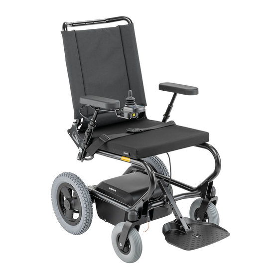
Product description 2.2 Product overview Back support Leg support with foot plate Arm support (flip-up) Caster wheel Control panel with joystick Drive wheel Seat cushion Anti-tipper with anti-tipper rollers Positioning belt (lap belt) Motors with brake release Cantilever frame Back support angle adjustment Battery cover Push bar 490E163=*... -
Page 8: Intended Use
Intended use 3 Intended use The safe use of the product can only be ensured in case of intended use in accordance with the information con tained in these instructions for use. The user is ultimately responsible for accident-free operation. 3.1 Indications for use The wheelchair is intended for indoor and outdoor transportation of people with temporary or permanent limitations of the ability to walk, inability to walk or difficulty standing up. -
Page 9: Side Effects
Safety WARNING Exceeding the service life Serious injuries due to failure to observe the manufacturer’s requirements ► Using the product beyond the specified expected service life leads to increased residual risk. ► Observe the specified service life. CAUTION Skin damage Skin damage or pressure points due to overloading ►... -
Page 10: Further Information
Safety INFORMATION ► Interference with other devices in the vicinity (e.g. alarm systems in department stores or automatic doors) by the product's own electromagnetic fields cannot be excluded. ► In this case, move your product out of interference range or turn off the power wheelchair's control device. 4.5 Further information INFORMATION The serial number required for enquiries and ordering spare parts and accessories is found on the nameplate. -
Page 11: Warning Labels
Delivery Label Meaning L Symbol for medical device M WARNING! Read the instructions for use before using the product. Observe important safety-related information (e.g. warnings, precautions). N Symbol for separate collection of electrical and electronic devices. Components of the power wheelchair and batteries may not be disposed of in household waste. -
Page 12: Preparing The Product For Use
Preparing the product for use Storage conditions • Store the power wheelchair in a dry, enclosed room with sufficient air circulation and protection from external influences. Specific information about storage conditions: see page 45. • Protect the wheels against ground frost, for example by taking all weight off them using an assembly stand or by setting them onto wooden blocks. -
Page 13: Settings
• Charging the battery (see page 26) • Folding up the backrest (see page 15) • Installing the arm supports (see page 14) 6.3 Settings The user or attendant may only perform the fine-tuning adjustments described in the following. The user should be sitting upright in the power wheelchair while making adjustments. -
Page 14: Removing/Installing The Arm Supports
INFORMATION Please contact the qualified personnel for subsequent adjustment of the control panel position. The arm supports offer the user support for the forearms. 7.2.1 Removing/installing the arm supports The arm supports can be removed if necessary. Removing the arm support 1) Pull out the clamping pins (clamps) by hand (see fig. 4, item 1). -
Page 15: Folding The Foot Plate Up/Down
7.3.1 Folding the foot plate up/down CAUTION Exposed pinch points Crushing, pinching due to incorrect handling ► Do not reach into the danger area with your fingers when folding the foot plate up or down. The user's feet can be placed on the footplate. To make getting into the wheelchair easier, the footplate can be folded up. -
Page 16: Getting In And Transferring
1) Pull out the clamping pins (clamps) by hand on the bottom of the back support tube on the right and left sides (see fig. 8, item 1). 2) Adjust the back support forward or back to the desired position (see fig. 8, item 2). 3) Reinsert the clamping pins (clamps) into the appro... -
Page 17: Buttons And Display Functions
Joystick [On/off] button [Decrease speed] button [Increase speed] button [Horn] button [Charge level] LED display [Selected speed level] LED display Charging receptacle 7.6.2 Buttons and display functions Joystick The speed and driving direction are controlled with the joystick (see page 22). [On/off] button Pressing this button turns the power wheelchair on or off (see page 21). -
Page 18: Driving Functions
Display Information Battery is charging Sequential indicator Battery charging urgently required Battery undervoltage (see page 43) Flashing* Battery overvoltage (see page 43) Notice: All five LEDs flash ten times briefly each. They briefly flash ten times again after a pause, etc. 10x flashing * The left LED flashes. - Page 19 CAUTION Driving in the dark Risk of collisions with other traffic participants due to lack of lighting ► Wear bright clothing or clothing with reflectors. ► Install active lighting on your product. ► Ensure that the reflectors on the product are clearly visible. Hazards during use of public transportation, elevators, lifting platforms CAUTION Use of elevators, lifting platforms...
-
Page 20: Driving Notes
7.7.2 Driving notes General information: • Prior to each use, the charge level of the batteries must be checked to avoid stalling due to drained batteries. • Beginners should always drive at a low speed level. • Always take curves slowly. •... -
Page 21: Switching On And Off
Further instructions for use • Attaching loads such as backpacks and the like can adversely affect stability. Therefore, suspending additional loads on the wheelchair is not permitted. The recommended overall width for category B power wheelchairs when ready for operation is 700 mm •... -
Page 22: Driving
Display Information Example: Selected speed level = 3 7.7.5 Driving WARNING Driving on unsuitable surfaces Risk of falling or tipping over due to operator error ► Do not operate the power wheelchair on very smooth surfaces (e.g. icy surfaces) or very rough surfaces (e.g. gravel or rubble). -
Page 23: Anti-Tipper
• Body weight of user • Tyres (air pressure, tyre tread depth) 7.7.7 Anti-tipper The anti-tipper rollers stabilise the power wheelchair when braking while driving downhill. The anti-tipper is mounted so that the ground clearance is at least 50 mm. 7.7.8 Drive-away lock INFORMATION This function is enabled. -
Page 24: Enabling/Disabling The Brakes
7.8 Enabling/disabling the brakes WARNING Uncontrolled rolling away Risk of collision with persons or nearby objects due to unlocked brakes ► Note that there is no braking function when the brakes are unlocked. The brake function may only be unlocked in the presence of an attendant. ►... -
Page 25: Batteries/Charging Process
7.9 Batteries/charging process 7.9.1 Safety instructions CAUTION Failure to check the charge level before putting into operation Injury to the user due to stopping suddenly, problems due to unplanned stalling ► Check the charge level of the batteries before each use. ►... -
Page 26: Battery Charger
7.9.4 Battery charger NOTICE Improper handling of the battery charger Damage to the battery charger, damage to the battery due to user error ► Only use battery chargers from Ottobock, which have been verified and approved by the manufacturer for use with the respective batteries (observe information on the battery charger). -
Page 27: Seat
WARNING Insufficient ventilation of the battery charger while charging Burns due to the battery charger overheating/catching fire ► Make sure the battery charger cannot overheat during the charging process. ► Ensure that the cooling fins/ventilation slots on the back of the device are not covered. NOTICE Improper charging Damage to the battery due to user error... -
Page 28: Seat Cushion
NOTICE Improper use Damage to the seat surface due to user error ► Do not allow the seat to come into contact with sharp objects. This also applies to animals such as pet cats with sharp claws. ► If the seat is expected to come into contact with liquid, such as spilt drinks or episodes of incontinence, always use it in conjunction with a liquid-repellent cover. -
Page 29: Use
• If the lap belt is too loose, the user can shift/slide out to the front. • During the assembly/adjustment, the lap belt is routed over parts of the seating system (e.g. over forearm sup ports or seat pads). This causes the lap belt to lose its retaining function. Adjusting the belt length 1) Position the user in the seat. -
Page 30: Additional Options
Putting on the positioning belt (lap belt) Prerequisite: Note the positioning instructions in > the previous section. 1) Push the two halves together until you hear the snap buckle engage (see fig. 15, item 1). WARNING! The positioning belt (lap belt) has to fit closely but not too tightly so the user is not injured. -
Page 31: Lighting (Not Intended For Road Traffic)
Overview of the lighting push-button module [Direction indicator left] button (with LED dis play) [Lights on/off] button (with LED display) [Warning flashers on/off] button [Direction indicator right – on/off] button (with LED display) [Lights on/off] button The front and rear lights are activated/deactivated by pressing this button. When the lighting is switched on, the LED above the button is illuminated. -
Page 32: Foot Positioning Belt
Swinging away the control panel holder 1) Apply some pressure to push the control panel holder to the side. → The pivot element is released. 2) Swing the control panel holder away to the side. INFORMATION: The pivot element locks in place again when the holder is rotated back to the original position. -
Page 33: Adaptation
7.12.4.1 Adaptation CAUTION Improper adjustments Injuries, malpositions, illness of the user due to adjustment changes ► The belt system is an important part of an individual seating unit/seating solution. Do not modify the installa tion position and basic settings established by the qualified personnel. ►... -
Page 34: Storage Bag
CAUTION Improper use Falls, user falling out due to improper use ► Only open the belt system and the applied lap belt when the user is ready to get out of the product. ► Do not leave the user unsupervised if the cognitive abilities of the user could lead to unintentional opening of the belt system. -
Page 35: Overview Of Additional Options
Using the storage bag 1) To open the storage bag, pull on the loop (see fig. 22, item 1) on the side until the magnetic clos ure is released (see fig. 22, item 2). 2) Fill the storage bag. 3) To close the magnetic closure, fold it against the tube of the base frame (see fig. 22, item 2/3). -
Page 36: Reducing The Transportation Size
NOTICE Incorrect lifting of the power wheelchair Damage to the power wheelchair due to failure to observe transportation instructions ► Be sure to lay the back support down onto the seat surface or place it in the vertical position before loading and for transporting the power wheelchair. -
Page 37: Use In Vehicles For Transporting Persons With Reduced Mobility
7.14 Use in vehicles for transporting persons with reduced mobility WARNING Use in vehicles for transporting persons with reduced mobility Serious injuries in case of accidents due to user error ► Always use the seats and personal restraint systems in the vehicle for transporting persons with reduced mobility first. - Page 38 WARNING Inadequate transportation safety Loss of safe restraint due to failure to observe transportation instructions ► Observe the following instructions for correct transport safety in the vehicle for transporting persons with reduced mobility. ► If necessary, instruct the qualified personnel on the following information. Securing the product in the vehicle for transporting persons with reduced mobility The wheelchair is secured in the vehicle for transporting persons with reduced mobility with the help of four belt loops, on which the vehicle side wheelchair restraint belts are attached.
-
Page 39: Restrictions For Use
4) Engage the hook of the vehicle side wheelchair restraint belt in both ends of the belt loop from the outside on the left and right sides respectively (see fig. 27, item 4). 5) Tighten the vehicle side wheelchair restraint belts at the front and rear as firmly as possible. -
Page 40: Care
Accessories* Transportation in a Remove option Secure option on vehicle for trans product porting persons with reduced mobil ity not possible Storage bag under the seat X*** Crutch holder X**** Beverage holder X*** Pocket for mobile phone X*** Control panel holder, swing-away, height- adjustable Foot positioning belt X*****... -
Page 41: Maintenance And Repair
Maintenance and repair 8 Maintenance and repair 8.1 Maintenance WARNING Insufficient maintenance Severe user injuries, damage to the product due to failure to observe maintenance intervals ► Only carry out the maintenance tasks described in this section. All other maintenance and service tasks may only be carried out by qualified personnel. -
Page 42: Repair
Maintenance and repair Component Activity Prior to Weekly Monthly every use Electronics Check whether the battery charger is functioning prop erly (inform qualified personnel of any LED error mes sages) Check plug connections Brake With brake unlocked: check whether the indicator on the control panel is flashing and an audible warning is emitted With brake engaged: check the braking function by try... -
Page 43: Procedure For Warnings And Error Messages
Maintenance and repair Error An error impairs one or more functions of the power wheelchair. The power wheelchair and its functions are not fully operational until the error is corrected. 8.3.2 Procedure for warnings and error messages • If a warning or error message appears, the power wheelchair can often no longer be driven. In this case, the error message must be noted and the control device has to be switched off. -
Page 44: Behaviour In Case Of Breakdowns
Disposal Flashing LED Error/warning Cause Possible measure If the plug connections are OK: Con tact qualified personnel Information for qualified personnel: Read the error code and proceed according to the service manual Brake release Brake disabled Check motor brakes Check connections to the controller 9x flash* Battery overvoltage Voltage too high... -
Page 45: Legal Information
Legal information 10 Legal information All legal conditions are subject to the respective national laws of the country of use and may vary accordingly. 10.1 Liability The manufacturer will only assume liability if the product is used in accordance with the descriptions and instruc tions provided in this document. - Page 46 Technical data Dimensions and weights Angle of the seat surface (seat inclina 4° tion)* Angle of leg to seat (knee angle) Minimum: 93°; maximum: 96° Distance from arm support to seat (arm 200–300 mm (7.9"–11.8") support height) Front position of the arm supports 92–172 mm (3.6"–6.8") Length of the forearm support 260 mm (10.2")
- Page 47 Technical data **** The braking distance can be correspondingly longer due to user weight, luggage and condition of the tyres, and due to weather and surface conditions. Driving distance range (on level surfaces)* All battery types Approx. 25 km (16 miles) * The specified driving distance range was determined under defined conditions according to ISO 7176-4. In prac tice, the driving distance range can be reduced by up to 50 per cent.
-
Page 48: Appendices
Appendices 12 Appendices 12.1 Threshold values for wheelchairs transportable by train INFORMATION ► The products in this series fully satisfy the minimum technical requirements of regulation (EU) No. 1300/2014 regarding train accessibility for people with disabilities. However, not all versions can comply with all threshold values due to different settings. - Page 49 490E163=*...
- Page 50 490E163=*...
- Page 51 · www.ottobock.de 143441 Moscow Region/Krasnogorskiy Rayon info@ottobock.com.co · www.ottobock.com.co Russian Federation Otto Bock Healthcare Products GmbH Otto Bock de Mexico S.A. de C.V. T +7 495 564 8360 · F +7 495 564 8363 Brehmstraße 16 · 1110 Wien · Austria Prolongación Calle 18 No. 178-A info@ottobock.ru · www.ottobock.ru F +43 1 5267985...
- Page 52 Ihr Fachhändler | Your specialist dealer Otto Bock Mobility Solutions GmbH Lindenstraße 13 · 07426 Königsee/Germany www.ottobock.com...
Need help?
Do you have a question about the 490E163 Series and is the answer not in the manual?
Questions and answers