
Subscribe to Our Youtube Channel
Related Manuals for Otto Bock 490E75 1 C Series


Summary of Contents for Otto Bock 490E75 1 C Series
- Page 1 490E75=1_C Instructions for use (user) ..................
- Page 2 490E75=1_C...
-
Page 3: Table Of Contents
Table of contents Table of contents Foreword ................................Product description ............................Function .............................. Product overview ..........................Intended use ..............................Indications for use ..........................Indications ............................Contraindications ..........................3.3.1 Absolute Contraindications ........................3.3.2 Relative Contraindications ........................Safety .................................. Explanation of warning symbols ...................... - Page 4 Table of contents 7.6.2.2 Buttons and display functions ....................... 7.6.2.3 Adjustment possibilities ........................7.6.3 R-Net control device with JSM-LED-L control panel ................. 7.6.3.1 Control panel ............................. 7.6.3.2 Buttons and display functions ....................... 7.6.3.3 Adjustment possibilities ........................7.6.4 R-Net control device with TEN° control panel/TEN° LCD module ..............
- Page 5 Table of contents 7.11.4 Power seat tilt ............................. 7.11.5 Combined seat height adjustment/seat tilt ....................7.11.6 Power back angle adjustment ....................... 7.11.7 Power legrests ............................ 7.11.8 Controlling power seat functions ......................7.11.8.1 VR2 control unit ..........................7.11.8.2 R-Net control unit ..........................
- Page 6 Table of contents Troubleshooting ..........................8.3.1 Types of notifications ......................... 8.3.2 Procedure for warnings and error messages ..................8.3.3 Wheelchair control unit error overview ....................8.3.4 Attendant control error overview ......................Behaviour in case of breakdowns ......................Disposal ................................Safety instructions ..........................
-
Page 7: Foreword
Foreword 1 Foreword INFORMATION Date of last update: 2020-10-23 ► Please read this document carefully before using the product and observe the safety notices. ► Obtain instruction from the qualified personnel in the safe use of the product. ► Please contact the qualified personnel if you have questions about the product or in case of problems. ►... -
Page 8: Product Overview
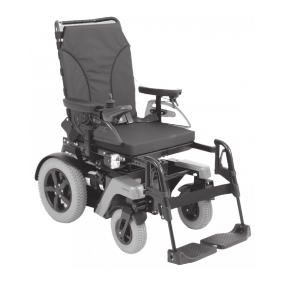
Product description • Individual control adaptation possibilities through programming and options. • Customisation using options (chassis, seating system, control device, accessories) • Compact design and ease of use. • Serviceability due to easy, straightforward access to all components. 2.2 Product overview Head support (option) Anti-tipper Attendant control (option) - Page 9 Product description Back support Anti-tipper Module carrier for control electronics (installa Caster wheel tion dependent on choice of options) Side panel with arm support Motor with brake release Back support angle adjustment (power adjust Front light ment, option) VAS seat Leg support (power adjustment, option) Rear light Seat cushion...
-
Page 10: Intended Use
Intended use 3 Intended use The safe use of the product can only be ensured in case of intended use in accordance with the information con tained in these instructions for use. The user is ultimately responsible for accident-free operation. 3.1 Indications for use The wheelchair is intended for indoor transportation, by the user, of people with temporary or permanent limitations of the ability to walk, inability to walk or difficulty standing up. -
Page 11: Safety
Safety 4 Safety 4.1 Explanation of warning symbols Warning regarding possible serious risks of accident or injury. WARNING Warning regarding possible risks of accident or injury. CAUTION Warning regarding possible technical damage. NOTICE 4.2 General safety instructions Hazards due to improper use of the product WARNING Improper product operation Falling, tipping over, collision due to user error... -
Page 12: Side Effects
Safety CAUTION Extreme temperatures Hypothermia or burns due to contact with components, failure of components ► Do not expose the product to any extreme temperatures (e.g. direct sunlight, sauna, extreme cold). ► Do not leave the product in the immediate vicinity of heaters. NOTICE Use under incorrect environmental conditions Damage to the product due to excessively high or low temperatures... -
Page 13: Nameplate And Warning Labels
Safety 4.6 Nameplate and warning labels 4.6.1 Signage on the product The warning signs and nameplates are attached at the following mounting points to the power wheelchair: 4.6.2 Nameplate The nameplates are found on the mobility base. Label Meaning A Manufacturer’s product name B CE marking C Maximum load (see section “Technical data”) D Maximum climbing ability (see section “Technical data”) -
Page 14: Warning Labels
Delivery YYYY = year of manufacture; MM = month of manufacture; DD = day of manufacture UDI-PI to GS1 standard; UDI = Unique Device Identifier, PI = Product Identifier UDI-DI to GS1 standard; UDI = Unique Device Identifier, DI = Device Identifier Rótulo/etiqueta Significado A ADVERTÊNCIA! Leia as instruções de utilização antes de usar... -
Page 15: Accessories
Delivery • Instructions for use (user) • Instructions for use for accessories (depending on equipment) 5.2 Accessories The standard model can be fitted to the user's personal requirements thanks to a large range of options. A full list of the available modules and accessories is shown on the order form and in the accessories catalogue. For use of the options, see the section "Use". -
Page 16: Preparing The Product For Use
Preparing the product for use The tyres should be replaced every 2 years regardless of wear and tear. • • When power wheelchairs with PU tyres are parked for longer periods, the tyres may become deformed (flat spots). This deformation will go away on its own over time while driving. 6 Preparing the product for use 6.1 Safety instructions WARNING... -
Page 17: Adjusting The Control Device
6.3.1 Adjusting the control device WARNING Incorrect configuration settings Falling, tipping over, collision due to programming errors ► Programming may only be performed by qualified personnel. The manufacturer of the product and the control device manufacturer are not liable in case of damage caused by programming which was not performed prop erly and/or which was not adjusted properly according to the user’s abilities. -
Page 18: Elevating The Side Panels
Removing the side panel 1) Loosen the thumb screw on the side panel holder (see fig. 5, item 1). 2) Pull the side panel out from the side panel holder and set it aside (see fig. 5, item 2). 3) Only for side panel with control panel: →... -
Page 19: Adjusting The Side Panels
Elevating the side panel 1) Turn the control device off. 2) Grasp the arm support with your hand. 3) Swivel up the side panel all the way to the stop (see fig. 7). Moving the side panel back to the front 1) Grasp the arm support with your hand. -
Page 20: Legrests
Adjusting the depth of the control panel position 1) Loosen the set screws on the bottom of the armrest (see fig. 10, item 1). 2) Slide the rail with the control panel forwards or backwards. INFORMATION: If the control panel rail is too long it can be shortened. -
Page 21: Adjusting The Leg Supports
INFORMATION For detaching/attaching the mechanically elevating leg supports: see page 82. The leg supports can be removed if needed to make getting in and out easier or for transportation. Removing the legrests 1) Fold up the footplate. 2) Push the legrest locking mechanism back and down (see fig. 12, item 1). - Page 22 Adjusting the lower leg length 1) If present: Remove the calf strap (not illustrated). 2) Loosen the set screw on the inside of the footplate bar (see fig. 14, item 1). 3) Adjust the footplate bar to match the user's lower leg length. INFORMATION: Ensure that the footplate bar is inserted into the swivel segment up to at least the marking (= 50 mm).
-
Page 23: Backrest
Adjusting the foot support angle 1) Loosen the Allen head screw on the foot support. 2) Turn the foot support to the desired angle. 3) Tighten the Allen head screw. Adjusting the foot support angle 1) Loosen the Allen head screw on the foot support (see fig. 19, item 1). -
Page 24: Adjusting The Back Support Angle
Folding up the back support 1) Fold the back support up. 2) Push the lock lever down (see fig. 21, item 1). 3) Place the cross bolt on the end of the actuator into the bracket (see fig. 21, item 2). 4) Release the lock lever until the cross bolt engages. 5) Check to ensure the lock is securely engaged by pulling on the back support. -
Page 25: Getting In And Transferring
4) Check to ensure the lock is securely engaged. Power back angle adjustment The back angle is adjusted as needed by using this seat function (see page 75). 7.5 Getting in and transferring CAUTION Incorrect handling when getting in Falling, tipping over due to incorrect handling ►... -
Page 26: Control Unit
Getting in from the front 1) Turn the control device off. 2) Fold up the foot supports (see fig. 25; item 1). If needed, swing the leg supports aside or remove them (see page 20). 3) Have an attendant assist you or use a transfer lifter to get into and out of the power wheelchair. -
Page 27: Buttons And Display Functions
Joystick [Decrease speed] button [Increase speed] button [Selected speed level] LED display [Horn] button [On/off] button [Charge level] LED display Charging/programming receptacle 7.6.1.1.1 Buttons and display functions Joystick The speed and driving direction are controlled with the joystick (see page 59). [On/off] button Pressing this button turns the power wheelchair on or off (see page 58). -
Page 28: Control Panel
Display Information Battery undervoltage, battery charging urgently required Flashing light Battery overvoltage Flashing light Further LED display functions Further LED display symbols are described in the following sections: • Section "Selecting the speed levels" (see page 58) • Section "Drive-away lock" (see page 61) •... - Page 29 [Seat function 1/2] LED display This LED display shows the currently active additional power function. [Horn] button The horn sounds as long as the button is pressed. [Warning flasher on/off] button All 4 warning flashers are activated/deactivated when this button is pressed. If the wheelchair is not fitted with lights for road traffic, this button is deactivated (no function).
-
Page 30: R-Net Control Device With Cjsm Control Panel
Display Information Battery overvoltage Flashing light Further LED display functions Further LED display symbols are described in the following sections: • Section "Selecting the speed levels" (see page 58) • Section "Drive-away lock" (see page 61) • Section "Troubleshooting" (see page 106) • Section "Power seat functions"... -
Page 31: Buttons And Display Functions
Back Connection for external [Mode] button Charging receptacle Connection for external [On/Off] button 7.6.2.2 Buttons and display functions LCD screen The LCD screen is the communication interface between the user and the control device. It indicates the selected profile, the battery charge level and the status of power options and special functions as well as warnings and errors. - Page 32 [Charge level] LCD screen Display Information Constant illumination – battery is charged Flashing slowly – charge battery immediately Row of lights illuminating individually – charging in progress Joystick The speed and driving direction in a driving profile (e.g. "Drive") are controlled with the joystick (see page 59). If the control device is in "Seating"...
-
Page 33: Adjustment Possibilities
Display Information when a brief joystick command is executed in the opposite direction; the wheelchair stops when the joystick is moved more than 50% in the opposite direction Message window with various information notices (see symbols below) Message in message window: The control device has to be restarted (symbol flashing) Message in message window: Configuration in progress, please wait Message in message window: Drive-away lock (see page 61) -
Page 34: R-Net Control Device With Jsm-Led-L Control Panel
• To call up the "Settings" menu, the [Slow Speed] and [Fast Speed] buttons have to be pressed at the same time for 1 second. • To navigate through the menu, move the joystick up and down. • The desired setting function (e.g. [Set Time]) is selected by moving the joystick to the right. -
Page 35: Buttons And Display Functions
The control panel consists of buttons, LED displays and the joystick. The charging/programming receptacle is on the underside. The control panel is used to switch the power wheelchair on and off, enter driving commands and display the cur rent status of certain functions and components. [Charge level] LED display [On/off] button [Lights on/off] button... - Page 36 Display Information Flashing light [Horn] button The horn will sound as long as the button is pressed. [Lights on/off] button and LED The front and rear lights are activated/deactivated by pressing this button. The LED above the button lights up after activation.
-
Page 37: Adjustment Possibilities
INFORMATION At temperatures of < 0 °C/32 °F the battery capacity drops by up to 35% in relation to the capacity for an outside temperature of 20 °C/68 °F. This shortens the range of the power wheelchair accordingly. Moreover at low tem peratures the charge level displayed on the control panel can differ more significantly from the actual battery capacity. -
Page 38: Push-Button Functions
Back side – TEN° control panel Transmitter for infrared signals Charging receptacle Connection for external [Profile] or [Pro file/mode] button (programmable) Connection for external [on/off] button 7.6.4.1.1 Push-button functions Joystick The speed and driving direction in a driving profile (e.g. "Drive") are controlled with the joystick (see page 59). If the control unit is in "Seating"... -
Page 39: Ten° Lcd Module
Rotary multi-selector left: [Decrease speed] Moving the rotary multi-selector to the left decreases the speed level (see page 58). The acoustic signal changes when the minimum speed level is reached. Depending on the programming of the control system, additional sym bols may be displayed when the rotary multi-selector is operated. External piko buttons Connected on the control panel (see fig. 35, item 3/4). -
Page 40: Display Functions
Menu"). Use the navigation buttons on the connected input device (e.g. joystick, special control input devices) to navigate within the operating modes. Navigation buttons These buttons can be used by the qualified personnel to navigate through the settings and programming menus. The user can navigate through the programmed menus and select functions. - Page 41 Restricted speed (creep speed/drive-away lock) User menu INFORMATION The scenario for standard programming is described below. The sequence of the sub-items can be varied indi vidually by the qualified personnel. The display shown above appears on the LCD screen of the TEN° LCD module after it is switched on. After pressing a connected user switch for the first time, the User Menu is displayed.
- Page 42 Display Function Provides access to user settings (e.g. setting the back light and time; see page ). Battery indicator [Charge level] The battery indicator [Charge level] is divided into 10 segments and shows the current charge level: • Immediately after the power wheelchair is switched on, the battery indicator shows the battery charge level that was saved before the wheelchair was last switched off.
- Page 43 Display Information "Specialty Control" profile This profile enables operation of a special control (e.g. chin control, sip and puff control). The profile image appears automatically on the LCD screen when the spe cial control is activated. Additional LCD display for model equipped with a gyro module Display Information "No Assist"...
- Page 44 Display Information Temperature warning Thermometer symbol lights up orange: e.g. overheating due to excessive load Connected additional input device (e.g. attendant control) Symbol next to the battery indicator lights up green: TEN° control panel or TEN° LCD module is active Connected additional input device (e.g. attendant control) Symbol next to the battery indicator lights up red: additional input device is act...
-
Page 45: Adjustment Possibilities
Display Information The control device has to be restarted (symbol flashing) Sleep symbol (control device is about to switch to sleep mode) This symbol is displayed during configuration procedures Procedure successful This symbol is displayed during configuration procedures Procedure unsuccessful This symbol is displayed during configuration procedures Procedure running;... - Page 46 TEN° control panel only: Press and hold the • [Warning flashers on/off] button to call up the “Settings” menu. TEN° LCD module only: Press the [Settings] but ton to call up the “Settings” menu. • Scroll up and down in the menus using the respect ive installed input devices (e.g. joystick, navigation buttons on the TEN° LCD module, special control input devices).
-
Page 47: Environmental Control Via Bluetooth
[Diagnostics] menu item For qualified personnel only. [Exit] menu item Exit the Settings menu by moving the joystick to the right. The display switches to the first driving profile. 7.6.4.5 Environmental control via Bluetooth NOTICE Use of devices with electromagnetic emissions Restriction of function due to electromagnetic fields ►... -
Page 48: Pairing
7.6.4.5.2 Pairing INFORMATION The name of the connected device (display name) can be customised by the qualified personnel (e.g. first name of the user, here "Tom"). Mutual authentication is required prior to initial Bluetooth communication between devices. This procedure, which needs to be carried out once for each device, is called "pairing". The procedure, which can also be carried out by an attendant if necessary, is described below. - Page 49 8) After the device has been added successfully, the Bluetooth symbol is continually displayed in blue on the LCD screen. Now the PC can be operated using respective installed input devices (e.g. joystick, navigation buttons on the TEN° LCD module, special control input devices). INFORMATION: If the connection is not estab...
- Page 50 10) After the device has been added successfully, the Bluetooth symbol is continually displayed in blue on the LCD screen. Now the Android device can be operated using the respective installed input devices (e.g. joystick, navigation buttons on the TEN° LCD module, special control input devices). Pairing with an iDevice INFORMATION Please observe the operating and configuration instructions of your iOS device.
-
Page 51: Selecting The Connected Devices
7.6.4.5.3 Selecting the connected devices LCD screen in "Bluetooth Device" mode Display Information The pairing is maintained as soon as the Bluetooth connection to the devices has been established. The device can be selected by scrolling (forwards/back). The selection is confirmed by moving right/left. After a few seconds, a Bluetooth symbol is continually displayed in blue on the LCD screen. -
Page 52: Operating Ios Device Functions
The qualified personnel can also change assignments using individual programming, for example so that a single input device movement is interpreted as a double-click. b) Mouse actions using external buttons: • One button corresponds to the left mouse button, the other button corresponds to the right mouse button. •... -
Page 53: Learning And Assigning Ir Codes
LCD screen in "IR Menu" mode Display Information When "IR Menu" mode is selected, a list of the devices that can be operated using environmental control is displayed. A list of assigned control commands (IR codes) is stored for each device. Using the example of a television set (TV), the following commands are available: [On], [Off], [Volume up], [Volume down], [Mute], [HDMI]. -
Page 54: Activating And Deactivating Ir Codes
Display Information Select the command which needs to be learned, e.g. [Volume down]. Select [Learn code]. Point the TV remote control towards the control panel or TEN° LCD module and press the desired button (e.g. [Volume down]) twice in succession. The learning pro gress is displayed on the control panel or TEN° LCD module in learning mode. -
Page 55: Driving Functions
Display Information Deactivating an IR code TEN° control panel: An IR code can be deactivated by turning the rotary multi- selector to the left. TEN° LCD module: An IR code can be deactivated by a movement to the left in the menu using the respective installed input device (e.g. joystick, +/- navigation buttons on the TEN° LCD module, special control input devices). -
Page 56: Driving Notes
CAUTION Safe positioning when using public transit Crushing, pinching, impacts, collision with persons or objects, damage to the product due to human error ► Only use public transit approved for the transportation of power wheelchairs. ► Always observe the current applicable transportation guidelines of the transit company and/or the legal requirements in your country when using public transit. - Page 57 • Note the information on the critical obstacle height (see the section "Technical data"). Crossing over obstacles greater than the height difference specified there is not permitted. • Avoid jumping down from steps. • Do not lean out of the wheelchair while crossing obstacles. •...
-
Page 58: Switching On And Off
7.7.3 Switching on and off WARNING Lack of brake functionality Falling, tipping over, collision with persons or nearby objects due to lack of inspection ► Ensure that the brake release lever is in the driving position every time before you drive (see page 64). ►... -
Page 59: Driving
• The pitch of the audible signal changes once the highest or lowest speed level is reached. • The [Selected speed level] LED display shows the speed level selected. Display Information Selected speed level = 3 • The power wheelchair has a programmable number of speed levels (delivery condition = 5 speed levels). •... -
Page 60: Range
WARNING Driving on slopes, over obstacles Falling, tipping over due to user error ► Only cross obstacles or negotiate ascents or descents that are within the permitted maximums. For more information, see the section "Technical data" (see page 117). ► Do not cross over any obstacles while ascending or descending inclines. ►... -
Page 61: Anti-Tipper
7.7.7 Anti-tipper The anti-tipper makes driving safer (see fig. 48). With rear-wheel drive, it prevents the wheelchair from tipping too far backward. 7.7.8 Drive-away lock 7.7.8.1 VR2 control unit INFORMATION This function is currently not enabled. For questions related to enabling it, please consult the qualified personnel that adapted the product or the manu facturer's service (see inside back cover or back page for addresses). -
Page 62: R-Net Control Unit
7.7.8.2 R-Net control unit INFORMATION This function is currently not enabled. For questions related to enabling it, please consult the qualified personnel that adapted the product or the manu facturer's service (see inside back cover or back page for addresses). The power wheelchair control unit features an electronic drive-away lock. -
Page 63: Adapting The Driving Characteristics
Activating the drive-away lock 1) Press and hold the [On/off] button while the control unit is turned on. 2) Release the [On/off] button after a beep sounds (approx. 1 second). 3) Push the joystick all the way forward until a beep sounds. 4) Push the joystick all the way back until a beep sounds. -
Page 64: Enabling/Disabling The Brakes
7.8 Enabling/disabling the brakes WARNING Uncontrolled rolling Risk of collision with persons or nearby objects due to unlocked brake ► Note the lack of brake functionality when the brake is deactivated. The brake function may only be released in the presence of an attendant. ►... -
Page 65: Batteries/Charging Process
Brake deactivated: warning on control panel Display Information Brake released Brake deactivated: warning on TEN° control panel or TEN° LCD module Display Information Brake unlocked 7.9 Batteries/charging process 7.9.1 Safety instructions CAUTION Failure to check the charge level before putting into operation Injury to the user due to stopping suddenly, problems due to unplanned stalling ►... -
Page 66: Battery Charger
• The batteries will gradually discharge if the wheelchair is not used for extended periods of time. If the power wheelchair is not used for an extended period, the batteries should be charged 1 x per week to maintain their capacity. - Page 67 WARNING Discharge of explosive gases during battery charging Burns due to explosion after a user error ► Ensure sufficient ventilation in enclosed spaces. ► Do not smoke or light fires. ► Sparks must be avoided. Switch the battery charger off and disconnect the mains plug before you disconnect the battery.
- Page 68 Charging process via the control panel 1) Turn the control device on the power wheelchair off. 2) Plug the battery charger plug into the charging receptacle on the power wheelchair control panel. INFORMATION: Please note that charging via the charging receptacle on the control panel may only be carried out at a current of maxim...
-
Page 69: Seat
5) Disconnect the battery charger plug from the con trol panel. 6) Turn the power wheelchair control unit on. The power wheelchair is ready to use. Charging process via the external charging recept acle 1) Turn the control device on the power wheelchair off. 2) Open the charging receptacle (see fig. 54, right). -
Page 70: Contoured Pads
The product is equipped with a VAS seat (Variable Adjust Seat). This seat type allows the technician to vary the seat depth, seat and back width and centre of gravity set tings. 7.10.3 Contoured pads The contoured pads provide the user with good lateral support. The contoured pads are offered in the flat contoured and deep contoured versions. -
Page 71: Cleaning The Covers
Putting on the cover 1) Remove the cover. 2) Slide the foam pad into the incontinence cover (top left). 3) Pull the open end of the incontinence cover up and lay it onto the foam pad (top right). 4) Pull the overhanging end of the incontinence cover down and close it on the underside of the foam pad (bottom). -
Page 72: Seat Cushion
With an anatomically shaped rigid back plate made of aluminium, the back system enables the best possible positioning. Large openings in the back shells provide for a low weight and easy handling. Detailed information regarding use, cleaning and main tenance can be found in the included instructions for use. -
Page 73: Power Seat Functions
7.11 Power seat functions 7.11.1 Safety instructions WARNING Driving with power seat functions Falling, tipping over due to driving with unallowable seat settings ► Only drive in road traffic and on inclines and downgrades with the seat tilt and seat height adjustments lowered and with a vertical backrest. -
Page 74: Speed Reduction
7.11.2 Speed reduction Depending on the configuration, using a seat adjustment may lead to a speed reduction. When speed reduction is active, this is indicated on the control panel as follows: VR 2 control device Display Information Restricted speed (creep speed) The [Selected speed level] LED display flashes: Automatic speed reduction (e.g. because a seat function was activated) R-Net control device –... -
Page 75: Power Seat Tilt
The power seat height adjustment feature raises the seat bottom by 350 mm (13.8") using a motor drive. The seat can be moved up continuously to the height specified. The driving function can be used indoors even when the seat is raised. The speed is decreased when the seat is raised (see previous section). -
Page 76: Power Legrests
INFORMATION ► Please also observe the generally applicable safety instructions in the section "Power seat functions" > "Safety instructions" (see page 73). ► Observe the instructions for use in the sections "Controlling power seat functions" (see page 77) and "Joy stick functions" (see page 79). The power back angle adjustment feature enables the backrest to be tilted up to 30°. -
Page 77: Controlling Power Seat Functions
The leg supports prevent a constant pressure load or provide anti-shock support. The leg supports can be operated individually or at the same time, depending on the configuration. The foot supports can be flipped up to increase the entry and exit area. In addition, the electrically adjustable leg supports can be lifted up and out of their brackets (item 1). -
Page 78: R-Net Control Unit
Version with a toggle for a third seat function • If the power wheelchair is equipped with three power seat functions, a toggle is mounted under the armrest on the control panel side. • The third seat function can only be activated when the LED display on the right is lit up ("Seat function 2"... -
Page 79: Joystick Functions
Procedure when using the TEN° LCD module • Activate the "Seating" mode by pressing the [Mode] button (see page 37 ff.). The LCD screen indicates the selected mode (see the following section). Depending on programming, the [Mode] button may need to be pressed a number of times. •... - Page 80 Display Function Deflection using the input device Power back support angle adjustment Back: Back support tilts backward Forward: Back support tilts forward Combined seat height adjustment and Forward: Seat functions move forward seat tilt Back: Seat functions move back Power leg support left Back: The left leg support moves up Forward: The left leg support moves down...
-
Page 81: Manual Seat Functions
JSM display Function Joystick deflection (standard setting) Power foot supports - right Forward: Right foot support moves for ward Back: Right foot support moves back Power foot supports, coupled Forward: Both foot supports move for ward Back: Both foot supports move back Direction of movement can be modified by the specialist dealer. -
Page 82: Manually Elevating Legrests
WARNING Lack of maintenance Severe user injuries, damage to the product due to maintenance errors ► Check the adjustment functions for visible signs of damage at least 1 x per month and ensure all screw con nections are tight. WARNING Exposed pinch points Pinching, crushing of limbs (e.g. fingers) due to lack of caution in danger areas, damage to the product ►... -
Page 83: Lap Belt
7.13 Lap belt The lap belt provides additional stabilisation and prevents the user from sliding out of the seat. 7.13.1 Adaptation CAUTION Improper adjustments Injuries, malpositions, illness of the user due to adjustment changes ► The belt system is an important part of an individual seating unit/seating solution. Do not modify the installa tion position and basic settings established by the qualified personnel. -
Page 84: Use
7.13.2 Use WARNING Incorrect application Throttling, suffocation or strangulation due to sliding forward in the product ► The lap belt must be put on when getting into the product and used at all times while using the product. ► Ensure that the buckle lies in the middle of the body. ►... -
Page 85: Suspension
7.14 Suspension This power wheelchair has drive wheel suspension as standard equipment. The suspension is located to the left and right of the battery case at the drive unit. 7.15 Control unit accessories 7.15.1 Attendant control 7.15.1.1 VR2 attendant control The power wheelchair has been equipped with a separate control panel for attendant operation. -
Page 86: R-Net Attendant Control
Pressing the button one more time returns to driving mode (seat function LED display is not lit). [Seat function 1/2] LED display This LED display shows the currently active additional power function. [Select speed level] button Pressing the button increases/decreases the speed level. The acoustic signal changes when the maximum speed level is reached. - Page 87 [Primary control active] LED display The red LED lights up when the attendant control is deactivated and the power wheelchair control panel is activ ated. [Mode] button Pressing this button toggles through the programmed profiles and operating modes. The joystick is used to navig ate within the profiles and operating modes (see above).
-
Page 88: Joystick Top
Display Information Attendant control active [Attendant control active] LED display The green LED lights up when the attendant control is activated and the user's control module is deactivated. [Primary control active] LED display The red LED lights up when the attendant control is deactivated and the user's control module is activated. [Mode] button Pressing this button toggles through the programmed profiles and operating modes. - Page 89 Swinging away the control panel holder 1) Apply slight pressure to push the control panel holder to the side. → The pivot element is unlocked. 2) Swing the control panel holder away to the side. INFORMATION: The pivot element locks in place again when the holder is rotated back to the original position.
-
Page 90: Lighting
7.16.2 Lighting Information on replacing broken lamps: see page 105. 7.16.2.1 Lighting for road traffic The installed lighting permits driving in road traffic during hours of darkness, and is only approved for use on motorised wheelchairs. The light, the right and left direction indicators and the warning flashers are operated via the control panel. Front lighting The front lighting consists of 2 front lights with integ... -
Page 91: Belts/Belt Systems
7.16.3 Belts/belt systems INFORMATION Information on the lap belt: see page 83. The following instructions for adjustment and use apply to four-way chest straps, upper body straps and vests as well as chest/shoulder straps. 7.16.3.1 Adaptation CAUTION Improper adjustments Injuries, malpositions, illness of the user due to adjustment changes ►... -
Page 92: Caster Wheel Swivel Lock
CAUTION Incorrect application Risk of pressure points, constriction due to user error ► Applies only to upper body straps/vests, chest/shoulder straps: Follow the positioning instructions. Ensure that the belt system lies against the chest evenly on both sides and is not too tight. ►... -
Page 93: Spring-Loaded Caster Fork
Engaging the caster wheel swivel lock 1) Push the release lever down and back (see fig. 84, item 1). 2) The caster wheel swivel lock bolt engages in the front fork. The power wheelchair drives straight in both forward and reverse. NOTICE! Please note that the caster wheel swivel lock function is mechanical and has no impact on the joystick functions. -
Page 94: Using The Product
WARNING Inflammable product Burns due to user error ► The product is flame retardant but nevertheless flammable. Therefore the utmost caution must be exercised in the vicinity of an open flame. ► Keep away from all ignition sources, especially lit cigarettes. CAUTION Improper adjustment Crushing or pinching due to adjustments which are too tight... -
Page 95: Cleaning
Readjusting the tray depth 1) Open the clamping lever on the swivel mechanism and pull the tray forward slightly (see fig. 87). 2) Pull the pin and swing the tray away to the side (see fig. 86). 3) Seat the user in the seat. 4) Fold the tray down and lock it with the pin. -
Page 96: Curb Climbing Assist
NOTICE Improper use of the seat tilt/back angle adjustment Damage to the luggage carrier due to collision with the seat back ► Note that the seat back may collide with the luggage carrier when the seat tilt or back angle adjustment is fully tilted. -
Page 97: Hand Heater
Possible connections: USB: The connection can be used to charge or operate devices with a standard USB battery charger (see fig. 91, item 1). Outputs: 5 V; to 1 A; 5 V to 2.1 A. 12 V: The connection can be used to charge or operate devices with a 12 V motor vehicle power adapter ("Cigarette lighter plug";... -
Page 98: Reducing The Transportation Size
CAUTION Securing the power wheelchair insufficiently during transport Crushing, pinching of body parts due to failure to observe transportation instructions ► During transportation in vehicles or aircraft, on lifting platforms or in lifts, turn the control unit of the power wheelchair off and lock the brake. -
Page 99: Preparing For Transport
7.17.3 Preparing for transport Transporting the power wheelchair 1) Position the power wheelchair in its transport loca tion. 2) Turn the control device off (see page 26 ff.). 3) Verify brake locking. It should not be possible to push the power wheelchair. If needed: Lock the brake (see page 64). - Page 100 The product must be sufficiently secured during transport in vehicles for transporting persons with reduced mobil ity. The illustrations that follow show an example for anchoring in a motor vehicle. The manufacturer is not responsible for the fastening systems that are used. Ensure that only fastening systems that meet the applicable legal requirements and are designed for the overall weight of the product including the user are used.
- Page 101 Securing the power wheelchair in the vehicle 1) Position the power wheelchair in the vehicle for transporting persons with reduced mobility. For more information, refer to section 5 in the brochure "Transporting persons with reduced mobility", order number 646D158. 2) Turn the control device off (see page 58). 3) Verify brake locking.
- Page 102 Information on correct transport safety of the user in the vehicle for transporting persons with reduced mobility • Using the personal restraint system of the vehicle for transporting persons with reduced mobility is required. Attaching personal restraint systems of the vehicle for transporting persons with reduced mobility to the wheel chair is not permitted.
-
Page 103: Prohibited Use
** The belt can be used to position the passenger during transportation. Using the personal restraint system is nev ertheless required. 7.18.4 Prohibited use WARNING Improper use in vehicles for transporting persons with reduced mobility Risk of serious injury when using the product as a seat ►... -
Page 104: Maintenance And Repair
Maintenance and repair 8 Maintenance and repair 8.1 Maintenance WARNING Insufficient maintenance Severe user injuries, damage to the product due to failure to observe maintenance intervals ► Only carry out the maintenance tasks described in this section. All other maintenance and service tasks may only be carried out by qualified personnel. -
Page 105: Repair
Maintenance and repair Component Task Prior to Weekly Monthly every use Lights Check for external damage Verify functionality Electronics Check that the control device is functioning properly (inform qualified personnel of any error messages on the control panel) Check that the battery charger is functioning properly (inform qualified personnel of any LED error messages) Check plug connections Brake... -
Page 106: Replacing The Battery
Maintenance and repair 8.2.3 Replacing the battery Batteries may only be replaced by qualified personnel. 8.3 Troubleshooting INFORMATION In the event of communication problems in the bus system of the controls, the system triggers an emergency stop and thus prevents any uncontrolled functions. ►... -
Page 107: Wheelchair Control Unit Error Overview
Maintenance and repair 8.3.3 Wheelchair control unit error overview INFORMATION Depending on the version or country-specific equipment, the list of relevant error messages may deviate from the overview provided here. VR2 control panel Flashing LED Error/warning Cause Possible corrective action Battery undervoltage Battery deep discharge Charge as soon as possible... - Page 108 Maintenance and repair Display Error/warning Cause Possible measure Fault on an actuator (seat e.g. defective cable, Check cabling/plug connections to function adjustment loose plug connection to defective actuator motor), defective actuat actuator or flashes Errors and warning messages in the message window on the CJSM control panel Display Contents Errors or warning messages appear in the message window with the following inform...
- Page 109 Maintenance and repair Error message Error no. Contents Cause Possible measure Left Lamp Short 7205 Short circuit in elec e.g. defective plug Check plug connec trical circuit of left connection, cable tions and cable to front/rear light break front/rear light Defective front/rear If error persists: con...
- Page 110 Maintenance and repair Error message Error no. Contents Cause Possible measure Error in control mod in displayed control nections and cables ules module If error persists: con Displayed control tact specialist dealer module defective System Error (None) System error Non-attributable error Check all plug con...
- Page 111 Maintenance and repair Error message Error no. Contents Cause Possible measure Electronic track sta is disrupted by the portation, select the biliser (gyro module) movement of a differ "No Assist" driving is activated ent means of trans profile for safety reas portation (e.g. train, ship) in standby...
- Page 112 Maintenance and repair Flashing LED Error/warning Cause Possible corrective action Fault on an actuator (seat e.g. defective cable, Check cabling/plug connections to function adjustment loose plug connection to defective actuator motor) actuator TEN° control panel; TEN° LCD module Display Error/warning Cause Possible action Emergency stop Serious control...
- Page 113 Maintenance and repair Error message Error no. Contents Cause Possible action If error persists, con tact qualified person M1 Motor Error 3B00 Left motor not con e.g. defective plug Check plug connec nected connection, cable tions and cable to break motor M2 Motor Error 3C00 Right motor not con...
- Page 114 Maintenance and repair Error message Error no. Contents Cause Possible action Memory Error (None) Unspecified memory e.g. defective plug Contact qualified error in control mod connection, cable personnel ules break Defective control module PM Memory Error (None) Memory error in con e.g. defective plug Check all plug con...
-
Page 115: Attendant Control Error Overview
Maintenance and repair Error message Error no. Contents Cause Possible action JS Static Timeout (None) Joystick holding time Excessive joystick Switch control device exceeded deflection detected off/on (control device stops error persists: drive system to pre replace control pan vent potential dam el/joystick;... -
Page 116: Behaviour In Case Of Breakdowns
Disposal Flashing LED Error/warning Cause Possible measure Attendant control fault Defective attendant control Switch off attendant control and turn control panel off/on Joystick error Attendant control joystick Switch off attendant control and move not in home position when joystick home position before the unit is turned on... -
Page 117: Lifetime
Technical data Depending on the model and version, malfunctions and faults of components relevant for safety as well as status messages of individual components are recorded. The data are available in anonymised/pseudonymised form when the data storage modules are read in case of service. Ottobock stores, processes and uses the data accord ing to the applicable data protection regulations. - Page 118 Technical data Dimensions – standard seat, small Effective seat width* 380–420 mm (15"–16.5") Front seat height* 380–500 mm (15"–19.7") Lower leg length** 150–470 mm (5.9"–18.5") Back support height 450/500/550 mm (17.7"/19.7"/21.6") * In increments of 20 mm ** In increments of 10 mm Dimensions – standard seat, large Effective seat depth* 420–500 mm (16.5"–19.7") If equipped with contour pads: 400–480 mm (15.7"–18.9")
- Page 119 Technical data Dimensions and weights (standard seat) Transport weights*** See "Weight", thereof weight of removable components: Leg support (standard): approx. 2.2 kg (4.9 lbs) Detachable side panel: approx. 3 kg (6.6 lbs) Leg support (power, with aluminium foot plate): approx. 6.5 kg (14.3 lbs) Minimum turning radius**** 800 mm (31.5") Turning circle**** 1335 mm (52.2")
- Page 120 Technical data * Depending on equipment and configuration ** Deviations are possible due to special seat configurations and other equipment versions *** Weight of the heaviest component **** Depending on configuration and options; specified value = smallest setting ***** DIN EN 12184, class A Transportation size (storage length x storage width x storage height) Storage length* 1100 mm (43.3")
- Page 121 Technical data Drive wheels Tyre type PU tyres Caster wheels Wheel size 10" Tyre type Pneumatic tyres Tyre pressure Adjust the tyre pressure according to the specifications on the tyre sidewall to prevent injuries or damage to the product: 3.5 bar/350 kPa/50 PSI Caster wheels Wheel size...
- Page 122 Technical data * The specified driving distance range was determined under defined conditions according to ISO 7176-4. In prac tice the driving distance range can be reduced by up to 50%. For information on this, see the section "Driving dis tance range"...
- Page 123 Technical data Battery charger (not delivered by Ottobock)* batteries to at least 80% within 8 hours; battery charger includes information regarding nominal capacity and the possibility of charging overnight; battery charger indicates that the battery is properly con nected) The device fulfils the normative requirements of ISO 7176-21 * For further details, see the instructions for use supplied with the battery charger.
-
Page 124: Appendices
Appendices Control device accessories Model TEN° LCD module Nominal input voltage 24 V Operating voltage range 16–33 V Absolute maximum voltage 35 V Weight Display module: 120 g Connection module: 200 g Case material Plastic Protection rating IPX4 IR frequency range 10–455 kHz Sip and puff control port Full puff pressure: approx. -
Page 125: Sound Emission Information
Appendices 12.2 Sound emission information INFORMATION ► The products in the series were tested for compliance with maximum sound emission requirements according to the ISO 7176-14 standard. ► They fully meet the requirements according to the areas of application identified below. Area of application Maximum sound pressure level In enclosed rooms... - Page 126 490E75=1_C...
- Page 127 · www.ottobock.de 143441 Moscow Region/Krasnogorskiy Rayon info@ottobock.com.co · www.ottobock.com.co Russian Federation Otto Bock Healthcare Products GmbH Otto Bock de Mexico S.A. de C.V. T +7 495 564 8360 · F +7 495 564 8363 Brehmstraße 16 · 1110 Wien · Austria Prolongación Calle 18 No. 178-A info@ottobock.ru · www.ottobock.ru F +43 1 5267985...
- Page 128 Ihr Fachhändler | Your specialist dealer Fabricante Legal: Otto Bock Mobility Solutions GmbH Lindenstraße 13 · 07426 Königsee/Germany www.ottobock.com Fabricado por: Ottobock Ind. E Com. Imp. E Export. De Cadeiras de Rodas Ltda Alfredo Achcar, 970. Bairro Nova Vinhedo 13280-000 – Vinhedo/SP – Brasil CNPJ: 20.445.801/0001-78...
Need help?
Do you have a question about the 490E75 1 C Series and is the answer not in the manual?
Questions and answers