Table of Contents
Advertisement
Quick Links
Advertisement
Table of Contents

Related Manuals for Barco XDL


Summary of Contents for Barco XDL
- Page 1 Installation Manual ENABLING BRIGHT OUTCOMES...
- Page 2 Barco NV President Kennedypark 35, 8500 Kortrijk, Belgium www.barco.com/en/support www.barco.com Registered office: Barco NV President Kennedypark 35, 8500 Kortrijk, Belgium www.barco.com/en/support www.barco.com...
- Page 3 Changes Barco provides this manual 'as is' without warranty of any kind, either expressed or implied, including but not limited to the implied warranties or merchantability and fitness for a particular purpose. Barco may make improvements and/or changes to the product(s) and/or the program(s) described in this publication at any time without notice.
- Page 4 Barco. If the purchaser or a third party carries out modifications or repairs on goods delivered by Barco, or if the goods are handled incorrectly, in particular if the systems are operated incorrectly or if, after the transfer of risks, the goods are subject to influences not agreed upon in the contract, all guarantee claims of the purchaser will be rendered invalid.
-
Page 5: Table Of Contents
HD for fully enclosed projection systems...........................17 HD in function of modifying optics ............................19 Radio equipment (optional) ...............................19 Download Product Manual ................................20 2 System overview....................................21 XDL series projector..................................22 Chillers and hoses..................................23 Safety system....................................25 3 Installation process....................................27 Preparation process ..................................28 Installation process ..................................28 Additional install options ................................29... - Page 6 7 Removal and installation of the projector covers....................75 Opening the front and rear cover doors ..........................76 Removal of the top cover................................76 Removal of the side covers ...............................77 A Dimensions........................................79 Dimensions of the XDL series projector..........................80 Glossary .........................................81 Index ..........................................83 R5906150 /05...
-
Page 7: Safety
Ensure that you understand and follow all safety guidelines, safety instructions and warnings mentioned in this chapter before installing the XDL projector. Clarification of the term “XDL” used in this document When referring in this document to the term “XDL” means that the content is applicable for following Barco products: •... -
Page 8: General Considerations
• Before operating this equipment please read this manual thoroughly and retain it for future reference. • Installation and preliminary adjustments should be performed by qualified Barco personnel or by authorized Barco service dealers. • All warnings on the projector and in the documentation manuals should be adhered to. -
Page 9: Safety Training To Be Provided By The Installer
1.2 Safety training to be provided by the installer Users definition The XDL projector is intended for persons who have been instructed and trained by a skilled person (installer or service personnel) to identify energy sources that may cause injury and to take precautions to avoid unintentional contact with or exposure to those energy sources. -
Page 10: Important Safety Instructions
The building installation has to be provided with a circuit breaker of 40 A to protect the complete unit. • REMARK for XDL-4K60/75 projector: In case of a Delta system (3W+PE) the circuit breakers rated lower than 40A can trip unwanted because of the internal laser power supply redundancy system. The projector remains working if one internal laser power supply module fails or is removed, but this results in a higher current in one mains power line. - Page 11 Safety • Lightning - For added protection for this video product during a lightning storm, or when it is left unattended and unused for long periods of time, remove all power from the projector. This will prevent damage to the projector due to lightning and AC power-line surges.
- Page 12 In the event of fire, use sand, CO or dry powder fire extinguishers. Never use water on an electrical fire. Always have service performed on this projector by authorized Barco service personnel. Always insist on genuine Barco replacement parts. Never use non-Barco replacement parts as they may degrade the safety of this projector.
- Page 13 Therefore a liquid cooling system is provided consisting of liquid circuits inside the projector which are connected via hoses to external chillers. Only chiller models and hoses exclusively developed for this application and approved by Barco are allowed to be used. Barco approved chillers models are listed on the Barco website.
-
Page 14: Product Safety Labels
Safety 1.4 Product safety labels Light beam related safety labels Label image Label description Label location Hazard RG3: not for household use symbol Hazard RG3: optical radiation warning symbol WARNING! DO NOT LOOK INTO THE LIGHT BEAM NO DIRECT EYE EXPOSURE TO THE BEAM IS PERMITTED. -
Page 15: High Brightness Precautions: Hazard Distance
Safety Electric related safety labels Label image Label description Label location Disconnect the power to the unit mains 200-240V 3W+PE XXA 50-60 Hz terminals and unplug power cord at UPS inlet Déconnecter l’alimentation des bornes du réseau et déconnecter le câble de la prise UPS pour la coupure de toute l’alimentation de l’appareil. - Page 16 Safety unrestrained behavior is reasonably foreseeable, the minimum separation height should be greater than or equal to 3.0 meter to prevent potential exposure, for example by an individual sitting on another individual's shoulders, within the HD. These values are minimum values and are based on the guidance provided in IEC 62471-5:2015 section 6.6.3.5.
-
Page 17: Hd For Fully Enclosed Projection Systems
The LIP shall be installed by Barco or by a trained and Barco-authorized installer or shall only be transferred to laser light show variance holders. This is applicable for dealers and distributors since they may need to install the LIP (demo install) and/or they transfer (sell, rent, lease) the LIP. - Page 18 Safety Restriction Zone (RZ) based on the HD The projector is also suitable for rear projection applications; projecting a beam onto a defuse coated projection screen. As displayed in Image 1– 3 two areas should be considered: the restricted enclosed projection area (RA) and the observation area (TH).
-
Page 19: Hd In Function Of Modifying Optics
The XDL is restricted to indoor use only when operating in the 5150 to 5250 MHz frequency range. Hereby, Barco declares that the radio equipment type XDL is in compliance with Directive 2014/53/EU. The full text of the EU declaration of conformity is available at the following internet address: https://www.barco.com/support... -
Page 20: Download Product Manual
Safety 1.9 Download Product Manual Download Product Manual Product manuals and documentation are available online at www.barco.com/td. Registration may be required; follow the instructions given on the website. IMPORTANT! Read Installation Instructions before connecting equipment to the mains power supply. -
Page 21: System Overview
Safety system ..........................25 About this chapter This chapter briefly describes all different components of the complete projection system based on the XDL series projector. For more detailed information related to the projector we refer to other chapters in this document. For the other components in the system we refer to its own documentation set of the component. -
Page 22: Xdl Series Projector
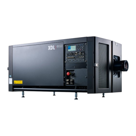
The XDL projector is a RGB laser-illuminated compact projector. This high-brightness laser projector is capable of showing 4K content at 120 fps and 3D content in full 4K resolution at 120 fps. The XDL–4K30 and 4k60 projectors have an integrated color 3D system, with 6-Primary (6P) color laser modules. This Barco Laser 3D system maximizes 3D efficiency from a single projector, delivering constant and uniform images in excellent contrast, without lamp flicker. -
Page 23: Chillers And Hoses
Projector ID label Air flow The XDL series projector has two air flow channels (reference A & B) to cool the projector electronics. The air intake is at the front side of the projector, the air outlet is at the back. - Page 24 Hoses Only hoses specified by Barco can be used to couple the cooling liquid of the chiller with the cooling circuit of the projector. The hoses specified are specially designed for this purpose. Using other hoses than those will...
-
Page 25: Safety System
Image 2–8 Hose with 90° angle male coupling. coupling. For chillers and hoses ordering information see Barco website. 2.3 Safety system Safety controller The projector is equipped with a safety controller which is located inside the mains compartment. This safety controller operates independent from the projector electronics and has its own power supply. - Page 26 System overview There are three cable glands (reference 4 Image 2–9) at the base of the mains compartment for the cabling of the external interlock devices. The projector is shipped with a connector of which the external beam enable key and the 2 external interlocks are bypassed.
-
Page 27: Installation Process
Installation process Preparation process........................28 Installation process ........................28 Additional install options........................29 About this chapter This chapter gives an overview of all the different stages in the installation process that has to be followed in chronological order to set the projector up and running. The stages are grouped in three processes: Preparation, Installation and Options. -
Page 28: Preparation Process
• Projector configuration: In case of a standing installation: ◦ Use a solid pedestal to place a single XDL projector on (with or without dedicated external frame) In case of a hanging installation: ◦ Use an external frame to suspend the XDL projector (Table Mount or Ceiling Mount). -
Page 29: Additional Install Options
Install the batteries of the Remote Control Unit (RCU). See chapter “Remote control, battery installation”, page Installation of the Projector Toolset on local laptop. Download and install the latest version from the Barco website. See chapter “Download Projector Toolset”, page Switch on the projector and start image projection. - Page 30 Installation process R5906150 /05...
-
Page 31: Installation Preparations
Download Projector Toolset ......................43 About this chapter Read this chapter before installing the XDL projector. It contains important information concerning installation requirements for the projector, such as minimum and maximum allowed ambient temperature, humidity conditions, required safety area around the installed projector, required power net, etc. -
Page 32: Installation Requirements
Therefore a liquid cooling system is provided consisting of liquid circuits inside the projector which are connected via hoses to external chillers. Only chiller models and hoses exclusively developed for this application and approved by Barco are allowed to be used. Barco approved chillers models are listed on the Barco website. - Page 33 Main Power requirements The XDL series projector operates from a nominal 3W+N+PE or 3W+PE power net. The projector must be switched internally between a star connection to a delta connection or vice versa. See installation instructions.
-
Page 34: Unpacking The Projector
The XDL series projector does not have a built in UPS unit. Projection screen The XDL series projector performs best when the image is projected on white screen with minimum gain (between 1 and 1.8). Very high gain screens (e.g. silver screens with gain 2.4) are not recommended. - Page 35 Installation preparations surrounded by foam. Once the projector has arrived at the installation site, it needs to be removed from its carton box and wooden/plastic pallet in a safe manner without damaging the projector. Required tools 10 mm Allen wrench. How to unpack the projector? Loosen the banding (reference 1 Image...
-
Page 36: Initial Inspection
This check should confirm that there are no broken knobs or connectors, that the cabinet and panel surfaces are free of dents and scratches, and that the operating panel is not scratched or cracked. The Barco Sales and Service office should be notified as soon as possible if this is not the case. -
Page 37: Projector Configurations
Installation preparations 4.4 Projector configurations The different configurations While the XDL projector can do both front projection as rear projection, the projector can only be installed in table-mount position. 1. Front / Table (F/T) 2. Rear / Table (R/T) Front projection The projector is installed at the same side of the screen as the audience. - Page 38 Installation preparations Positioning the projector Image 4–5 Positioning the projector The projector should be installed at right angles (horizontally and vertically) to the screen at a distance PD. Note the distance (A) between lens centre and table surface is slightly variable. This distance (A) is nominal 223 mm in case all feet are turned in completely and the vertical lens shift is set to zero (0).
- Page 39 Installation preparations +75% +75% -35% +35% -60% -35% -60% +35% Image 4–6 Vertical and horizontal shift range Field of view It is mechanical possible to shift outside the recommended field of view, but it will result in a decline of image quality depending on the used lens and the zoom position of the used lens. Furthermore, shifting too much in both directions will result in a blurred image corner.
-
Page 40: Additional Vertical Shift Of The Lens Holder
Introduction The lens of the XDL can be shifted vertically. The maximum vertical shift range is –65 to +75%, which is not sufficient in some situations. To extend the vertical shift range in a certain direction, the Lens Holder can be shifted manually. -
Page 41: Available Lenses
Close the front projector cover again. 4.6 Available lenses Which lenses are available for my projector? The table below is subject to changes and was last updated on 20/02/2018. Consult Barco's web site for the most recent information about available lenses. Type... -
Page 42: Lens Selection
How to select the right lens Determine the required screen width (SW). Determine the approximate position of the projector in the room. Start up the Lens Calculator on the Barco website: https://lenscalculator.barco.com/ to determine the possible lenses for your configuration. -
Page 43: Download Projector Toolset
4.9 Download Projector Toolset About Projector Toolset Projector Toolset is a software tool to set up, configure, manage and control Barco projectors. The Projector Toolset software works with configurations that can be loaded. Several configurations can be controlled simultaneously. Even when the configurations are connected via different ways. - Page 44 Installation preparations To download the reference manual, select Reference Guide and download the latest version of the manual for your projector. Installation Download first the reference manual and follow the installation instructions as written in this manual. R5906150 /05...
-
Page 45: Installation Procedures
Installation procedures Remote control, battery installation ....................46 Removing the transport protection bars ..................47 Connecting the hoses with projector and chillers ................48 Connecting the data cable with projector and chillers...............49 Accessing the mains compartment....................50 Connecting the external safety interlocks..................51 Three phase power input configuration of the projector ..............52 Connecting the projector with the mains electricity................54 Power loop through to the projector electronics ................55 5.10 Connecting a UPS to the projector electronics ................56... -
Page 46: Remote Control, Battery Installation
Installation procedures 5.1 Remote control, battery installation Where to find the batteries for the remote control ? The batteries are not placed in the remote control unit to avoid control operation in its package, resulting in a shorter battery life time. At delivery the batteries can be found in a separated bag attached to the remote control unit. -
Page 47: Removing The Transport Protection Bars
Installation procedures CAUTION: Replace with the correct battery type. Use two AA size batteries. There is a risk of explosion if the battery is replaced with an incorrect type. CAUTION: Replace the battery as explained above. There is a risk of explosion if the battery is incorrectly installed. -
Page 48: Connecting The Hoses With Projector And Chillers
This procedure assumes that the chiller(s) and projector are already installed. It is also advised to use the XDL accessory kit and install the support frames before you connect the hoses and use the hose shells after connecting the hoses. See the Accessory kit installation manual for more details. -
Page 49: Connecting The Data Cable With Projector And Chillers
Next to connecting the hoses, the communication port of the chillers has to be connected with each other and with the projector. Depending on the projector model one or two chillers are required! For the XDL-4K30 series projector one chiller has to be installed. The XDL-4K60/75 series needs two chillers. -
Page 50: Accessing The Mains Compartment
Installation procedures Image 5–8 5.5 Accessing the mains compartment Required tools • Phillips screwdriver PH1 • Torx screwdriver T10 • Allen wrench 3 mm How to access the mains compartment? Loosen the four retaining screws (reference 1 Image 5–9) of the mains cover. Remove the mains cover. -
Page 51: Connecting The External Safety Interlocks
Installation procedures Image 5–10 Loosen the retaining screw (reference 3 Image 5–11) of the inner front door (door with the Stop button). Use a 3 mm Allen wrench. Pivot the inner front door to have full access the mains compartment parts. Image 5–11 5.6 Connecting the external safety interlocks The terminal for the external safety interlocks is located inside the mains compartment. -
Page 52: Three Phase Power Input Configuration Of The Projector
Installation procedures Note: Only remove the shunt wires from these pins which have to be connected with an external safety interlock device. All other shunt wires must remain in place. Note: Maximum two external safety interlock devices can be connected. These interlock devices must have double pole normal open contacts. - Page 53 Installation procedures Image 5–13 Υ/Δ configuration block (left: delta, right: star) WARNING: Ensure that the mains is disconnected from the projector prior to start with this procedure. The Υ/Δ configuration block is located inside the mains compartment. This procedure assumes that the cover of the mains compartment is already removed.
-
Page 54: Connecting The Projector With The Mains Electricity
Installation procedures Image 5–15 Take off the mounted links (A, B and C). Connect the left pins together. Place 2 links between the upper pin and the middle pin (A, B) and 1 link between the middle pin and the lower pin (C). 5.8 Connecting the projector with the mains electricity WARNING: The total electrical installation should be protected by an appropriate rated and readily... -
Page 55: Power Loop Through To The Projector Electronics
Image 5–17) which was delivered with the projector. Warning: Always use the Barco short power cable which is delivered with the projector. Secure both plugs of the short cable with a fixation spring (reference 2 Image 5–17). Handle as follow: •... -
Page 56: Connecting A Ups To The Projector Electronics
Installation procedures Image 5–17 5.10 Connecting a UPS to the projector electronics WARNING: Only use UPS units which are suitable for the XDL series projector. See chapter “Installation requirements” for more information about the requirements of the UPS. Required tools No tools required. -
Page 57: Lens Installation
Installation procedures CAUTION: The electrical connection with the UPS INLET socket of the projector must be done with a certified AC power supply cord (minimum 0,75 mm² or 18 AWG and minimum 300V) CAUTION: Do not use the power OUTLET socket of the projector to provide power to other equipment! 5.11 Lens installation How to install a lens into the Lens Holder? -
Page 58: Lens Safety Cable
• 4 x Cable clip (16x16 mm, Ø4 mm) • XDL safety cable bracket kit How to mount the cable Paste four cable clips on the lens as illustrated (reference 1). Orient the open side of the clips towards the front of the lens. - Page 59 Installation procedures Image 5–22 Image 5–23 Snap the first loop end of the safety cable into the upper clip on the side of the cable bundle (reference 2, Image 5–22). and let the loop end point downwards. Slide the rest of the cable around the lens counterclockwise. Click the cable into every clip it passes in this loop.
- Page 60 Installation procedures Image 5–25 Close the U-bolt and tighten it. Note: Make sure the safety cable is tightened around the lens before tightening the U-bolt nuts. Place the shackle through the free loop end of the safety cable. How to mount the cable Make sure the transport protection bars are removed from the projector.
-
Page 61: Lens Removal
Installation procedures Image 5–27 5.13 Lens removal How to remove a lens from the Lens Holder? Support the lens with one hand while you unlock the lens holder by sliding the lock handle (reference 1 Image 5–28) towards the “unlocked” position as illustrated. Gently pull the lens out of the lens holder, maintaining its coaxial direction. -
Page 62: Using The Xlr Connector Of The Rcu
Installation procedures How to Program an Address into the RCU? Press the Address button until the Button pressed indicator lights up continuously (proximately 5 seconds). Enter the address with the digit buttons within the time the indicator lights up (also proximately 5 seconds). Note: That address can be any value between 0 and 31. -
Page 63: Alignment Of A Table Mounted Projector
For detailed instructions see user guide of the projector. 5.17 Alignment of a table mounted projector Barco offers a pedestal for the XDL series projector. This pedestal allows for a solid and easy setup of the projector and chillers that fit underneath the pedestal. -
Page 64: Installation Of An Input Board
When this is achieved, the projector is set horizontal and vertical at right angles to the screen. Image 5–31 Angle adjustment 5.18 Installation of an input board WARNING: The procedures below may only be performed by Barco trained and qualified technicians. CAUTION: Always wear a wrist band which is connected to the ground while handling the electrostatic discharge (ESD) sensitive parts. -
Page 65: Removal Of An Input Board
5.19 Removal of an input board WARNING: The procedures below may only be performed by Barco trained and qualified technicians. CAUTION: Always wear a wrist band which is connected to the ground while handling the electrostatic discharge (ESD) sensitive parts. -
Page 66: Software Update
Download the latest firmware (format .fw) from Barco's website in the same way as for Projector Toolset. Start Projector Toolset and make a connection with the projector. For more information, see the “Projector Toolset”... - Page 67 Power on the projector. Wait until the Power on/off button is either lit white or blue. Download the latest firmware file ( format .fw) from Barco's website. The firmware can be downloaded for free from Barco's website, (URL: http://www.barco.com). Click on myBarco and log in to get access to secured information.
- Page 68 Always contact Barco if you want to make sure a downgrade will not hurt your device.
-
Page 69: Pulse Sfp Input Use Cases
Pulse SFP input use cases Use case 1: SFP+ transceiver + Fiber connection (integrated or separated) ........70 Use case 2: Neutrik OpticalCon Duo + SFP+ transceiver + internal fiber ...........71 Use case 3: Neutrik OpticalCon Quad + SFP+ transceiver + internal fiber .........72 Use case 4: Loop-through mode ....................73 About this chapter This chapter describes the several use cases of the SFP input. -
Page 70: Use Case 1: Sfp+ Transceiver + Fiber Connection (Integrated Or Separated)
Optional breakout Optical adapter Dustproof Gasket Barco delivers only the SFP input and SFP+ fiber transceivers. The customer has to buy the SFP+ transceiver and the optional breakout adapter or the fiber integrated cable. How to configure the SFP input Remove the plate covering the access to the SFP cages. -
Page 71: Use Case 2: Neutrik Opticalcon Duo + Sfp+ Transceiver + Internal Fiber
Neutrik OpticalCon DUO Cable Internal fiber cable Barco delivers only the SFP input and SFP+ fiber transceivers. The customer has to buy the SFP+ transceiver and the optional breakout adapter or the fiber integrated cable. How to configure the SFP input Remove both plates covering the access to the Neutrik connector locations. -
Page 72: Use Case 3: Neutrik Opticalcon Quad + Sfp+ Transceiver + Internal Fiber
Advanced quad cable Internal fiber cable Barco delivers only the SFP input and SFP+ fiber transceivers. The customer has to buy the SFP+ transceiver and the optional breakout adapter or the fiber integrated cable. How to configure the SFP input Remove one plate covering the access to a Neutrik connector location. -
Page 73: Use Case 4: Loop-Through Mode
Neutrik OpticalCon Quad Advanced Quad cable Barco delivers only the SFP input and SFP+ fiber transceivers. The customer has to buy the SFP+ transceiver and the optional breakout adapter or the fiber integrated cable. How to configure the SFP input Remove both plates covering the access to a Neutrik connector locations. - Page 74 Pulse SFP input use cases R5906150 /05...
-
Page 75: Removal And Installation Of The Projector Covers
Removal and installation of the projector covers Opening the front and rear cover doors ..................76 Removal of the top cover.......................76 Removal of the side covers ......................77 WARNING: Switch off the projector prior to opening or removing the projector covers, unless otherwise specified in the procedure. -
Page 76: Opening The Front And Rear Cover Doors
Removal and installation of the projector covers 7.1 Opening the front and rear cover doors This procedure assumes that the lens is removed and that the hoses are disconnected from the projector. This procedure is applicable for all four cover doors. To access the thumbscrews of the top cover it is sufficient to open de cover doors a few centimeters. -
Page 77: Removal Of The Side Covers
Removal and installation of the projector covers Image 7–2 Slide the top cover in horizontal direction a few centimeters away from the center of the projector (this to unhook), then remove it from the projector. Image 7–3 7.3 Removal of the side covers The illustrations in this procedure are based on the left-side cover. - Page 78 Removal and installation of the projector covers Remove the two screws located at the middle bottom of the side cover (reference 4Image 7–4). Use a 3 mm Allen wrench. Lift up the side cover about two centimeters and then remove it from the projector. Image 7–4 R5906150 /05...
-
Page 79: A Dimensions
Dimensions R5906150 /05... -
Page 80: Dimensions Of The Xdl Series Projector
Dimensions A.1 Dimensions of the XDL series projector Dimensions PONT OF GRAVITY EXIT DRAIN EXIT DRAIN 1135 293,5 293,5 33,3 33,3 1446 741,6 117,5 1211 117,5 Image A–1 R5906150 /05... -
Page 81: Glossary
Glossary Broadcast address Projector will always execute the command coming from a RCU programmed with that broadcast address. Dew point The dew point is the saturation temperature for water in air. The dew point is associated with relative humidity. A high relative humidity implies that the dew point is closer to the current air temperature. Relative humidity of 100% indicates the dew point is equal to the current temperature and that the air is maximally saturated with water. - Page 82 Glossary R5906150 /05...
-
Page 83: Index
Remove 75 Access Mains compartment 50 Additional vertical shift Lens Holder Delta (Δ) configuration 52 additional 40 Dimensions 79 Lens Holder 40 XDL 80 vertical shift 40 DMD cooling 24 Address Download Program Product manual 20 RCU 61 Projector Toolset 43... - Page 84 Index Input & communication unit Front projection 37 Communication board Rear projection 37 Installation 64 Removal 65 Input board Installation 64 Physical Installation 45 Removal 65 Positioning 38 Install Power input setup 52 Covers 75 Power loop through Hoses 48 Installation 55 Lens 57 Prepare...
- Page 85 Shift range 38 Side cover Remove 77 Software update 66 Stacking 34 Star (Y) configuration 52 System overview 21 Chillers and hoses 23 XDL 22 Table mounted projector Alignment 63 Three phase Configuration 52 Tilt range Horizontal 39 Vertical 39...
- Page 86 Index R5906150 /05...
- Page 88 R5906150 /05 | 2021-08-02 www.barco.com...
Need help?
Do you have a question about the XDL and is the answer not in the manual?
Questions and answers