
Related Manuals for Barco DP2K C


Summary of Contents for Barco DP2K C
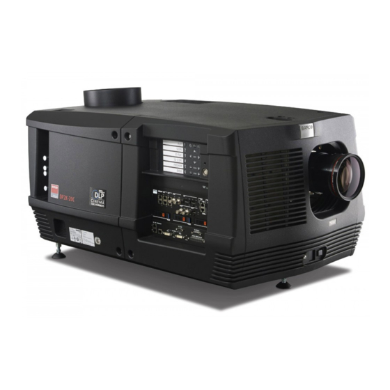
- Page 1 DP2K C For DP2K-12C, DP2K-15C, DP2K-20C User and Installation manual ENABLING BRIGHT OUTCOMES...
- Page 2 Barco NV Beneluxpark 21, 8500 Kortrijk, Belgium www.barco.com/en/support www.barco.com Registered office: Barco NV President Kennedypark 35, 8500 Kortrijk, Belgium www.barco.com/en/support www.barco.com...
- Page 3 Changes Barco provides this manual 'as is' without warranty of any kind, either expressed or implied, including but not limited to the implied warranties or merchantability and fitness for a particular purpose. Barco may make improvements and/or changes to the product(s) and/or the program(s) described in this publication at any time without notice.
- Page 4 Barco. If the purchaser or a third party carries out modifications or repairs on goods delivered by Barco, or if the goods are handled incorrectly, in particular if the systems are operated incorrectly or if, after the transfer of risks, the goods are subject to influences not agreed upon in the contract, all guarantee claims of the purchaser will be rendered invalid.
- Page 5 Trademarks Brand and product names mentioned in this manual may be trademarks, registered trademarks or copyrights of their respective holders. All brand and product names mentioned in this manual serve as comments or examples and are not to be understood as advertising for the products or their manufacturers.
-
Page 7: Table Of Contents
Installation of the lamp house ..............................51 Resetting the lamp parameters...............................53 Realignment of the lamp in its reflector ..........................54 5 Lenses & lens holder..................................57 Available lenses....................................58 Lens selection....................................58 Lens installation ....................................59 Lens removal.....................................62 Lens shift, zoom & focus................................62 Scheimpflug adjustment................................64 R5905752 /16 DP2K C... - Page 8 10.9 Installation of the top cover..............................131 10.10 Installation of the rear cover..............................132 10.11 Installation of the side cover ..............................132 10.12 Installation of the front cover..............................133 10.13 Installation of the input cover..............................134 R5905752 /16 DP2K C...
- Page 9 Pin configurations of the ICMP-X communication ports..................167 Pin configurations of the inputs............................170 C Environmental information................................ 171 Disposal information................................... 172 Turkey RoHS compliance................................ 172 Contact information..................................173 Production address..................................173 Download Product Manual ..............................173 Glossary ........................................175 Index ..........................................179 R5905752 /16 DP2K C...
- Page 10 R5905752 /16 DP2K C...
-
Page 11: Safety
DP2K-xxC projector. Furthermore, it includes several cautions to prevent damage to the DP2K-xxC projector. Ensure that you understand and follow all safety guidelines, safety instructions and warnings mentioned in this chapter before installing the DP2K-xxC projector. R5905752 /16 DP2K C... -
Page 12: General Considerations
• Before operating this equipment please read this manual thoroughly and retain it for future reference. • Installation and preliminary adjustments should be performed by qualified Barco personnel or by authorized Barco service dealers. • All warnings on the projector and in the documentation manuals should be adhered to. -
Page 13: Important Safety Instructions
Switch off the projector and unplug the power cord from the UPS INLET for removal of all power from the projector. • Warning: High leakage current. Earth connection essential before connecting supply. • Do not allow anything to rest on the power cord. Do not locate this projector where persons will walk on the cord. R5905752 /16 DP2K C... - Page 14 UV exposure for an-8 hour day to be less than 0,1 micro-watts per square centimeters of effective UV radiation. An evaluation of the workplace is advised to assure employees are not exposed to cumulative radiation levels exceeding these government guidelines. R5905752 /16 DP2K C...
- Page 15 Do not place flammable or combustible materials near the projector! • Barco large screen projection products are designed and manufactured to meet the most stringent safety regulations. This projector radiates heat on its external surfaces and from ventilation ducts during normal operation, which is both normal and safe.
- Page 16 Replacement parts: When replacement parts are required, be sure the service technician has used original Barco replacement parts or authorized replacement parts which have the same characteristics as the Barco original part. Unauthorized substitutions may result in degraded performance and reliability, fire, electric shock or other hazards.
-
Page 17: Safety Precautions Hazardous Chemicals
Safety Data Sheets for Hazardous Chemicals For safe handling information on chemical products, consult the Safety Data Sheet (SDS). SDSs are available upon request via safetydatasheets@barco.com. 1.4 High Brightness precautions: Hazard Distance Hazard Distance (HD) is the distance measured from the projection lens at which the intensity or the energy per surface unit becomes lower than the applicable exposure limit on the cornea or on the skin. - Page 18 (RZ) in the theater must be established. This can be done by using physical barrier, like a red rope as illustrated in Image 1–3. The restricted area sticker can be replaced by a sticker with only the symbol. R5905752 /16 DP2K C...
-
Page 19: Hd For Fully Enclosed Projection Systems
: the distance that has to be kept restrictive related to the reflected light from the rear projection reflection screen. • : the relevant distance to be considered while observing the diffuse surface of the rear projection diffuse screen. R5905752 /16 DP2K C... -
Page 20: Hd In Function Of Modifying Optics
5000 diffuse cd/m² or 15000 LUX. 1.6 HD in function of modifying optics Hazard Distance DP2K-20C DP2K-15C DP2K-12C Throw Ra o Image 1–5 Hazard Distance in meter Throw Ratio R5905752 /16 DP2K C... -
Page 21: General
DP2K-20C • DP2K-20Cx Barco provides a guarantee relating to perfect manufacturing as part of the legally stipulated terms of guarantee. Observing the specification mentioned in this chapter is critical for projector performance. Neglecting this can result in loss of warranty. -
Page 22: Installation Requirements
The projector must be installed with sufficient space around the projector head, minimum 20 cm (8 inch) to ensure sufficient air flow. For PRC (People's Republic of China) the certified altitude is specified on the product label. R5905752 /16 DP2K C... - Page 23 In no event shall this projector be operated without an adequate cabinet ground connection. The AC supply must be installed by a qualified electrician in conformance to local codes. Hardware, wire sizes and conduit types must comply with local codes. R5905752 /16 DP2K C...
-
Page 24: Unpacking The Projector
DP2K-20Cx ±102 kg (±225 lb.) Barco offers a pedestal for the DP2K-xxC. This universal pedestal allows a solid and easy setup of the projector. The universal pedestal has a separate compartment to install the UPS unit for the DP2K-xxC. Futhermore, the universal pedestal contains a standard 19” rack to build in the projector peripherals such as alternative content switchers. - Page 25 Rotate the wooden support plate with projector 90° and slide the front side over the edge of the pallet until the fixation screw (reference 4) is visible as illustrated. Remove the hexagon socket head cap screw (reference 4). Use an 8 mm Allen wrench. 90° Image 2–4 R5905752 /16 DP2K C...
-
Page 26: Initial Inspection
Save all packing material until the inspection is completed. If damage is found, file claim with carrier immediately. The Barco Sales and Service office should be notified as soon as possible. -
Page 27: Installation Process Overview
This check should confirm that there are no broken knobs or connectors, that the cabinet and panel surfaces are free of dents and scratches, and that the operating panel is not scratched or cracked. The Barco Sales and Service office should be notified as soon as possible if this is not the case. - Page 28 See the user guide of the Communicator (Touch Panel) for more detailed information. (not for Taiwan market) In case the projector is equipped with an Integrated Media Block (IMB) or Integrated Media Server (IMS) see user guide of the IMB or IMS for detailed instructions. (Not for Taiwan market) R5905752 /16 DP2K C...
-
Page 29: Physical Installation
This chapter describes how the mechanical set up of the projector has to be done and how to realize the electrical connections. The light pipe is made out of magnesium. If used in high humidity conditions, there might be some corrosion visible. However, this does not affect the performance of the projector. R5905752 /16 DP2K C... -
Page 30: Positioning The Projector At The Port Window
20 cm Image 3–1 Positioning at port window Barco offers a pedestal for the projector. This universal pedestal allows a solid and easy setup of the projector. The universal pedestal has a separate compartment to install the UPS unit (if available) for the projector. - Page 31 Tilt the projector to closely match this screen tilt angle as follows: • Loosen the nuts (A), using a wrench of 17 mm, on the threaded rod. • Adjust the height of the legs until the projected image matches the projection port window and the screen tilt. R5905752 /16 DP2K C...
-
Page 32: Installation Of The Exhaust System
CAUTION: The projector may tilt maximum 15° forward and maximum 15° backwards. This includes the tilt created by the projector feet and the tilt created by the pedestal. Barco offers a pedestal for the projector. This pedestal allows you to easily tilt the projector forward up to 6°. -
Page 33: Connecting The Projector With The Power Net
It is possible to convert the top exhaust into a rear exhaust. For that you need to order the upgrade kit “Rear cover with air exit”. For ordering information see Barco website. 3.3 Connecting the projector with the power net WARNING: The total electrical installation should be protected by an appropriate rated and readily accessible disconnect switch, circuit breakers and ground fault current interrupters. - Page 34 Guide the AC power cord through the cable gland and connect the wires to the 3-terminal strip as illustrated. Warning: Always connect first the PE wire. Image 3–7 Secure the power cord with the chassis of the projector by using two cable ties (A) and by fastening the cable gland (B) as illustrated. R5905752 /16 DP2K C...
-
Page 35: Power Loop Through To The Projector Electronics
INLET/OUTLET fixation accessories The plugs of the power cable which are inserted in the power INLET or OUTLET socket of the projector have to be secured. The projector is equipped with fixation accessories as illustrated below. R5905752 /16 DP2K C... - Page 36 Plug in the short power cable (reference 4) which was delivered with the projector. Warning: Always use the Barco short power cable which is delivered with the projector. Secure both plugs of the short power cable with a fixation plate. Use two thumbscrews (reference 5) per fixation plate.
-
Page 37: Connecting A Ups With The Projector Electronics
CAUTION: The electrical connection with the UPS INLET socket of the projector must be done with a certified AC power supply cord (minimum 0,75 mm² or 18 AWG and minimum 300V) CAUTION: Do not use the power OUTLET socket of the projector to provide power to other equipment! R5905752 /16 DP2K C... - Page 38 Physical installation R5905752 /16 DP2K C...
-
Page 39: Lamp & Lamp House
WARNING: Always wear face protection (full face shield) when handling xenon lamps. WARNING: Always wear protective clothing (welder's jacket) when handling xenon lamps. WARNING: Always wear clean leather gloves with wrist protectors when handling xenon lamps. R5905752 /16 DP2K C... -
Page 40: Introduction
A cathode adaptor is required to mount the xenon lamp in the lamp house. The cathode adapter has to be mounted upon the cathode side of the xenon lamp prior to mounting the lamp in the lamp house. The purpose R5905752 /16 DP2K C... -
Page 41: Removal Of The Lamp House
CAUTION: Due to its high internal pressure, the lamp may explode in either hot or cold states if improperly handled. Required tools • Flat screw driver or • Nut driver 8 mm How to remove the lamp house of the projector Switch off the projector. Remove the lamp cover. R5905752 /16 DP2K C... -
Page 42: Removal Of The Xenon Lamp
WARNING: DO NOT PERMIT UNAUTHORIZED PERSONNEL TO PERFORM OR ATTEMPT ANY PHASE OF XENON LAMP HANDLING OR SERVICE. ONLY TRAINED AND QUALIFIED TECHNICAL SERVICE PERSONNEL ARE ALLOWED TO HANDLE THE XENON LAMP. WARNING: This procedure may only be performed by qualified technical service personnel. R5905752 /16 DP2K C... - Page 43 Release the xenon lamp from its socket by removing the hexagon socket head cap screw and washer as illustrated. Use a 5 mm Allen wrench. Image 4–6 Remove the Lamp House side cover by releasing the two retaining thumbscrews as illustrated. R5905752 /16 DP2K C...
- Page 44 Support the xenon lamp inside the Lamp House with one hand while removing the UV blocker assembly from the Lamp House. Note that some xenon lamps are installed with an anode adaptation bushing. Caution: Ensure that you wear protective clothing, a full face shield and protective gloves. Image 4–9 R5905752 /16 DP2K C...
- Page 45 Remove the cathode lamp adaptor (reference 11) from the xenon lamp (reference 13) as illustrated. Use a 5 mm Allen wrench to release the adaptor fixation screw (reference 12) of the adaptor. R5905752 /16 DP2K C...
-
Page 46: Installation Of The Xenon Lamp
WARNING: Always wear face protection (full face shield) when handling xenon lamps. WARNING: Always wear protective clothing (welder's jacket) when handling xenon lamps. WARNING: Always wear clean leather gloves with wrist protectors when handling xenon lamps. R5905752 /16 DP2K C... - Page 47 5 mm Allen socket. Make sure that there is full contact between the cathode adapter and the lamp base. Note: Do not take the lamp out of its protective container or protective cloth while mounting the adapter. 2, 5 N m Image 4–14 Mount cathode adaptor R5905752 /16 DP2K C...
- Page 48 While inserting the lamp, rotate it slightly, engaging the pins of the cathode adapter in the foreseen slots. This is to ensure the lamp cathode is completely inserted. Image 4–16 Lamp bulb installation Warning: Make sure that the both pins of the cathode adapter are engaged in the foreseen slots. R5905752 /16 DP2K C...
- Page 49 Secure the UV blocker by fastening the four retaining thumbscrews as illustrated. Note: Please ensure that the thumb screws turning wires are flush with the cover or interference will occur while inserting the lamp house into the projector. R5905752 /16 DP2K C...
- Page 50 This cathode connection must be checked with every lamp change! Caution: Do not tighten the first nut (reference 1) against the connector housing. There must be some play (1 mm maximum). This is important to insert the Lamp House smoothly into the projector. R5905752 /16 DP2K C...
-
Page 51: Installation Of The Lamp House
4.5 Installation of the lamp house WARNING: This procedure may only be performed by qualified technical service personnel. CAUTION: Due to its high internal pressure, the lamp may explode in either hot or cold states if improperly handled. R5905752 /16 DP2K C... - Page 52 Image 4–25 Secure lamp house Reinstall the lamp cover of the projector. While starting up the projector, the electronics detect if a lamp is installed. If no lamp is installed, it is not possible to start up the projector. R5905752 /16 DP2K C...
-
Page 53: Resetting The Lamp Parameters
Fill out the serial number of the lamp (8). Click Reset (9). Image 4–26 Reset lamp info CAUTION: For more information about using the Communicator Touch Panel consult the user's guide of the Communicator Touch Panel. R5905752 /16 DP2K C... -
Page 54: Realignment Of The Lamp In Its Reflector
Set the “Light output mode” in normal mode and the “Lamp Dimming” on maximum (255). Note: This window on the Communicator touch panel shows in the upper left corner the measured value of the built-in light sensor of the projector. R5905752 /16 DP2K C... - Page 55 Do this for each direction and repeat this adjustment cycle twice. Image 4–29 Lamp adjustment If lock nuts are available, these nuts can be locked again. Switch off the projector. Reinstall the cover of the lamp compartment. R5905752 /16 DP2K C...
- Page 56 Lamp & Lamp House R5905752 /16 DP2K C...
-
Page 57: Lenses & Lens Holder
CAUTION: Never transport the projector with a lens mounted in the lens holder. Always remove the lens before transporting the projector. Neglecting this can damage the lens holder and prism. Each time a lens is manipulated (e.g. removed and installed in a projector), it needs to be homed and returned. R5905752 /16 DP2K C... -
Page 58: Available Lenses
Lenses & lens holder 5.1 Available lenses Available lenses The table below is subject to changes. Consult Barco's web site for the most recent information about available lenses. Type Zoom range Image Product Number R9855957 Motorized 1,2 – 1,81 Image 5–1... -
Page 59: Lens Installation
5.3 Lens installation How to install a lens into the projector lens holder ? Remove the plastic lens holder cover. 1. Put the lock (1) into the unlock position. 2. Take out the plastic cover. R5905752 /16 DP2K C... - Page 60 Ensure that the lens holder stands in the On-Axis position (horizontal and vertical mid position). Note: The lens holder is placed default in the On-Axis position at factory. Gently insert the lens in such a way that the lens connector matches the socket (B). R5905752 /16 DP2K C...
- Page 61 CAUTION: Never transport the projector with a lens mounted in the lens holder. Always remove the lens before transporting the projector. Neglecting this can damage the lens holder and prism. R5905752 /16 DP2K C...
-
Page 62: Lens Removal
It's recommended to place the plastic lens holder cover of the original projector packaging, back into the Lens opening to prevent intrusion of dust. 5.5 Lens shift, zoom & focus Motorized lens adjustment The projector is equipped with a motorized lens shift functionality and a motorized zoom & focus functionality. R5905752 /16 DP2K C... - Page 63 How to focus Is the projector equipped with a motorized zoom & focus? ► If yes, use the “+” and “-” focus keys on the local keypad to focus the image on the screen. R5905752 /16 DP2K C...
-
Page 64: Scheimpflug Adjustment
The DMD plane, the principal lens plane and the sharp focus plane will intersect in a line below the projector for downward lens tilt. R5905752 /16 DP2K C... - Page 65 Fully loosen lock nut 4. See Image 5–18. Optimize the focus of the projected image as follows: 1. Place the zoom lens in TELE position (smallest projected image) and adjust the focus using the lens focus barrel or motorized focus control. R5905752 /16 DP2K C...
- Page 66 3. Repeat steps “a” and “b” until the projected image is as sharp as possible. Image 5–20 Center focusing Sharpen bottom left corner of the screen by adjusting nut 1. Image 5–21 Left bottom focusing Sharpen bottom right corner of the screen by adjusting nut 2. R5905752 /16 DP2K C...
- Page 67 Start the fixation as follows (steps must be followed strictly) : Turn in set screw A, B and C. Tighten lightly (by hand). Tip: Any movement of the image will affect the Scheimpflug adjustment Fasten lock nuts a, b and c. R5905752 /16 DP2K C...
- Page 68 Tighten nut 4 until the offset of the image movement created in go to step 3 is canceled. Tip: The amount of image movement in steo 3 will determine how tight the nut in step 5 will need to be turned to return the image to its original position. R5905752 /16 DP2K C...
-
Page 69: Input & Communication
This chapter describes the functionality of the Local Keypad, the projector Status Light (tail light) and the different input and communication ports of your projector. Note that all information about the ICMP-X is gathered into one separated chapter. R5905752 /16 DP2K C... -
Page 70: Introduction
Removing one of the boards (except for the Cinema Controller) will result in an authorization request upon starting. 6.2 Local keypad Identification of the keys Image 6–2 Local keypad Marker area for macro name Numeric keyboard Standby key Dowser open/close switch R5905752 /16 DP2K C... -
Page 71: Integrated Cinema Processor (Icp)
In case the projector is equipped with an ICMP-X no ICP board is inserted. All ICP functionality is integrated in the ICMP-X. LEDs and ports on the Integrated Cinema Processor POWER STAT STAT STAT STAT CINEMA CONT Image 6–3 R5905752 /16 DP2K C... -
Page 72: Integrated Cinema Processor - Direct (Icp-D)
Cage of the projector. The ICP-D process and formats DCI cinema content played from a Media Block and delivers it to the projector (DMDs). In case the projector is equipped with a Barco ICMP-X no ICP-D board is inserted. All ICP-D functionality is integrated in the Barco ICMP-X. - Page 73 GDC SX4000: From software version 10.00 (build 103) onward • QSC CMS-5000: From software version 1.1.01818+ onward This list is subject to change. Please contact Barco service to obtain the updated list of supported IMB brands (models, minimum software version, etc). ICP-D LEDs, communication and input ports Image 6–4...
-
Page 74: Icp-D Hdmi 2.0 Specifications
For the ICP-D HDMI 2.0 specifications, see “ICMP-X HDMI 2.0 specifications”, page 107. 6.6 HD-SDI Input Module (optional) Not available for purchase at Barco for use in Taiwanese market. Depending on the projector configuration the projector card cage is either equipped with an ICP(-D) or ICMP-X. - Page 75 Progressive SF - 2nd field dominant Progressive SF- 1st field dominant 4:4:4 12 Progressive XYZ/ bits/color Progressive - field bit normal Progressive - field bit inverted Progressive SF- 2nd field dominant Progressive SF- 1st field dominant R5905752 /16 DP2K C...
- Page 76 3G - Level A - Single bits/color Interleaved Dual (separate left / right eye) 3G - Level B - Single Interleaved Dual (separate left / right eye) 4:4:4 12 Progressive XYR/ 3G - Level A - Single bits/color Interleaved R5905752 /16 DP2K C...
- Page 77 Calibration space 3GSDI 3D HFR 4:2:2 10 Progressive YCbCr 3G - Level A - Single bits/color Interleaved Dual (separate left / right eye) Progressive SF- 1st YCbCr 3G - Level A - Single field dominant Interleaved R5905752 /16 DP2K C...
-
Page 78: Integrated Media Block/Server (Optional)
/ right eye) 6.7 Integrated Media Block/Server (optional) Not available for purchase at Barco for use in Taiwanese market. Depending on the projector configuration the projector card cage is either equipped with an ICP(-D) or ICMP-X. In case an ICP(-D) is installed then an IMB, IMS, or HDSDI input module can be optionally inserted into the slot below the ICP(-D). -
Page 79: Cinema Controller
3D interface port (reference 5 Image 6–8. Can be used to connect external 3D devices to the projector. All signals necessary for 3D projection can be provided via this connector. The 3D interface port is disabled if the projector is in Standby mode. R5905752 /16 DP2K C... - Page 80 29 pins that handles both digital and analog video. This standard uses TMDS (Transition Minimized Differential Signal) from Silicon Image and DDC (Display Data Channel) from VESA (Video Electronics Standards Association). DVI can be single or dual link. R5905752 /16 DP2K C...
- Page 81 10 bit Twin DVI ACS (2048x1080) 50/59.94 Progressive RGB 4:4:4 12 bit DVI-3D 3D (2048x1080) Progressive RGB 4:4:4 2x8 bit DVI-3D 3D (2048x1080) Progressive RGB 4:4:4 2x8 bit DVI-3D 3D (2048x1080) Progressive RGB 4:4:4 2x8 bit R5905752 /16 DP2K C...
- Page 82 Input & communication R5905752 /16 DP2K C...
-
Page 83: Icmp-X
7.18 ICMP-X reset ..........................113 About this chapter This chapter describes the ICMP-X in general, the HDDs, the input ports and the communication ports. Furthermore, the status LEDs are described and the importance of the device certificate is illustrated. R5905752 /16 DP2K C... - Page 84 ICMP-X Image 7–1 R5905752 /16 DP2K C...
-
Page 85: Icmp-X Introduction
HDDs for ICMP-X As an integrated component of the projector, installation and maintenance of the ICMP-X requires the same skills and the same precautions as an intervention on the projector itself. For order info see www.barco.com. Front face of the ICMP-X 0123456789 Image 7–3 Front face ICMP-X (standard with storage controller GEN 2) - Page 86 ”, page 89. It’s possible to upgrade an ICMP with a GEN2 storage controller. For more info about the upgrade kit and instructions see Barco website. How to recognize an ICMP-X or an upgraded ICMP with GEN2 storage controller At the first glance ICMP-X is very similar to ICMP (the previous generation device) however both devices are not fully compatible and not interchangeable.
-
Page 87: Icmp-X Hdd
An upgraded ICMP with GEN 2 storage controller has a label “SSD READY - RAID GEN2” applied under the Barco logo). This sticker comes with the upgrade kit; it will only be there when the “upgrader” applied it. Image 7–7 It’s useful to recognize an ICMP from an ICMP-X or upgraded ICMP to know which HDDs can be... - Page 88 ICMP-X. The HDD spare part kits provided by Barco are configured by default to work with a GEN1 storage controller and it is necessary to perform a manual RAID initialization when they are deployed on a GEN2 storage controller.
-
Page 89: What Are The Possible Hdd Swaps
ICMP-X HDD models validated by Barco Only the original HDD spare parts provided by Barco or models validated by Barco (see list below) can be used in the ICMP-X. All deviations from this rule void warranty. HDD model ICMP-X ICMP 1TB: HGST –... -
Page 90: Installing A Hdd Into The Icmp-X
This procedure assumes that the HDD slot of the ICMP-X is empty. If not, see procedure “Removing a HDD from the ICMP-X”, page 92. CAUTION: Always use a new empty spare part HDD approved by Barco to replace a malfunction HDD. Do not use a HDD from another ICMP-X HDD set. - Page 91 200 GB per hour. Once the RAID is completed the red LED turns off. CAUTION: It's strongly recommended to complete the RAID recovery process prior to starting a show. This to ensure that the content integrity is preserved and that the show is not interrupted. R5905752 /16 DP2K C...
-
Page 92: Removing A Hdd From The Icmp-X
Image 7–12 Push the unlock button to open the handle. Image 7–13 Pull the HDD out of its slot. Image 7–14 To install an HDD, see the following procedure: “Installing a HDD into the ICMP-X”, page 90. R5905752 /16 DP2K C... -
Page 93: Hdd Status Leds
See procedure via the (Web) Commander. See user guide of the “Removing a HDD from the ICMP-X”, page 92, (Web) Commander. and “Installing a HDD into the ICMP-X”, page 90. Ensure to insert the HDD firmly. R5905752 /16 DP2K C... -
Page 94: Icmp-X Status Leds
(All red LEDs remain off) + Combination of three installed storage controller (see list of HDD errors (10580 “local storage not available”, 10585 models validated by Barco). “storage mount failed”, 10573 “the RAID is 2. Start “RAID Initialize”. See user guide of the broken”) -
Page 95: Icmp-X Device Certificate
7.8 ICMP-X device certificate Purpose of the Barco ICMP-X device certificate The device certificate (*. pem) of the Barco ICMP-X is a digital certificate signed by Barco which is required when ordering the KDM to play a DCP that is ingested on the ICMP-X. The device certificate is stored inside the ICMP-X and on a web server. - Page 96 The KDM is a small file, and is typically emailed to the exhibitor. To create the correct set of KDMs for a site requires knowledge of the digital certificate in the projection system´s media block. R5905752 /16 DP2K C...
-
Page 97: Obtaining The Icmp-X Certificate
Using control software to obtain the ICMP-X certificate Use your control software to download the ICMP-X certificate from the ICMP-X main board. For detailed instructions, refer to the user guide of your control software, or the projector User Guide. R5905752 /16 DP2K C... -
Page 98: Icmp-X Configuration Via Communicator
Verify internal clock of the ICMP-X. All installation and maintenance operations on the ICMP-X are performed via Communicator, the Barco configuration software. Please refer to the Communicator user guide for further information. About Default settings The restore of factory setting is a feature that allows removing all settings performed on the ICMP-X and replaces them with the default values set at the factory. -
Page 99: Icmp-X Communication Ports
These RJ45 connectors can be used to receive trigger signals from other devices. The mapping of the General Purpose Input (GPI) on each input Cues is configured via the Communicator software. Please refer to the Communicator user guide for further information. R5905752 /16 DP2K C... -
Page 100: Icmp-X Source Input Ports
ICMP and ICMP-X equipped with two HDMI 2.0 (Reference 8, Image 7–20) as video source. Image 7–20 ICMP-X (with HDMI 2.0). ICMP with DisplayPorts (Reference 11, Image 7– 21) and HDMI 1.4 (Reference 10, Image 7– 21) are still present on the field. R5905752 /16 DP2K C... -
Page 101: Icmp-X Network Streaming (Live Ip) Specifications
LIVE_IP (used to set Live IP as the input of the video mezzanine board) need to be present on the projector. To do this both the following methods are available: a new clone package that contain Icmp_Live_IP.INPUT file (and LIVE_IP macro) could be apply with (Web) Communicator. R5905752 /16 DP2K C... -
Page 102: Icmp Displayport Specifications
The specification is proprietary, and implementing HDCP requires a license. DisplayPort specifications Supported Modes: • DP1.1a, 4-lanes RBR/HBR • Audio : yes • Content Protection : HDCP1.4 • Color Depth : 8 bit/component and 10 bit/component. R5905752 /16 DP2K C... - Page 103 DisplayPort A and DisplayPort B automatically detect: Active Pixels, and Active Lines Vertical Refresh 8 bits/color - 10 bits/color Frame locked • All input resolutions are scaled towards the desired resolution specified in the screen presentation file. R5905752 /16 DP2K C...
-
Page 104: Icmp-X Sdi Specifications
1080p 50/60 (Level A) 3Gb/s 1080p 4:4:4 (Level B) 3G HD-SDI uses a higher data rate (2.97 Gb/s). This allows a single cable interface to achieve the same capabilities of a Dual-Link HD-SDI implementation. Not supported in Alchemy R5905752 /16 DP2K C... - Page 105 SMPTE 274M 1920 x 1080 23.976 23.976 Segmented frame SMPTE 428-9 2048 x 1080 Y Cb Cr 4:2:2 10-Bit (SMPTE RP211) 29.97 29.97 SMPTE 274M 1920 x 1080 Interlaced 29.970 59.940 Y Cb Cr 4:2:2 10-Bit R5905752 /16 DP2K C...
- Page 106 The Dual-Link HD-SDI interface can be used to carry a single 4:4:4 image, having a color depth of 10 or 12 bit per component. Both RGB (XYZ) and Y Cb Cr color spaces are supported. mainly used to carry stereoscopic images. R5905752 /16 DP2K C...
-
Page 107: Icmp-X Hdmi 2.0 Specifications
HDMI is a digital replacement for existing analog video standards. HDMI 2.0 specifications HDMI only supported in 3G level A mapping, others formats are supported in both level A and level B mapping. R5905752 /16 DP2K C... - Page 108 The ICMP is not supporting Ethernet-over-HDMI and such specific cables are thus not required. HDMI 2.0 Supported 2D Formats Color coding Bit depth Format Frame Rate 1280x720 23.976 YCbCr 4:4:4 YCbCr 4:2:2 29.97 59.94 1280x720 119.88 YCbCr 4:4:4 YCbCr 4:2:2 1920x1080 23.976 2048x1080 YCbCr 4:4:4 YCbCr 4:2:2 29.97 R5905752 /16 DP2K C...
- Page 109 YCbCr 4:4:4 YCbCr 4:2:2 3840x2160 23.976 4096x2160 24 25 YCbCr 4:4:4 29.97, 30 YCbCr 4:2:2 3840x2160 4096x2160 59.94 YCbCr 4:4:4 YCbCr 4:2:2 HDMI 2.0 Supported Audio Formats Sample Rate Sample coding Bit depth Format L-PCM 44.1 88.2 R5905752 /16 DP2K C...
-
Page 110: Icmp Hdmi 1.4 Specifications
HDMI- compliant device ("the source device") to a compatible computer monitor, video projector, digital television, or digital audio device. HDMI is a digital replacement for existing analog video standards. R5905752 /16 DP2K C... - Page 111 YCbCr 4:2:2 1280x720 23.976 YCbCr 4:4:4 YCbCr 4:2:2 29.97 59.94 119.88 1680x720 23.976 YCbCr 4:4:4 YCbCr 4:2:2 29.97 59.94 119.88 1920x1080 23.976 2048x1080 YCbCr 4:4:4 YCbCr 4:2:2 29.97 59.94 1920x1080 2048x1080 119.88 YCbCr 4:4:4 YCbCr 4:2:2 R5905752 /16 DP2K C...
- Page 112 HDMI 1.4 Supported 3D (Frame Packing) Formats Color coding Bit depth Format Frame Rate 1280x720 59.94 1920x1080 23.98 HDMI 1.4 Supported 3D (Top Bottom) Formats Color coding Bit depth Format Frame Rate 1280x720 59.94 1920x1080 23.98 R5905752 /16 DP2K C...
-
Page 113: Icmp-X Reset
► If yes, perform a hardware reset as follows: 1. switch off the lasers of the projector or switch of the projector lamp. 2. press the ICMP-X hardware reset button a few seconds (reference 3 Image 7–22) . R5905752 /16 DP2K C... - Page 114 ICMP restarts. Image 7–22 WARNING: Resetting the ICMP-X with the hardware reset button may cause damage to the content on the HDDs. A re-configuration of the whole system may be required! R5905752 /16 DP2K C...
-
Page 115: Communicator Touch Panel
Communicator touch panel Introduction ..........................116 Installing the touch panel interface ....................117 Reposition the touch panel interface..................... 118 R5905752 /16 DP2K C... -
Page 116: Introduction
The touch panel interface requires a +12 VDC voltage, 1,5 ampere. The use of a separate +12 VDC adaptor (1,5 ampere minimum) is required. Parts location of the touch panel interface Image 8–2 Communicator touch panel A Touch screen B Communication panel C Knob to operate central swivel clamp D Base of swivel arm R5905752 /16 DP2K C... -
Page 117: Installing The Touch Panel Interface
Slide a washer (M) over the base of the swivel arm and Insert the base of the swivel arm into the mounting hole at the top of the DP2K-xxCas illustrated. Image 8–4 Mount swivel arm Place the touch panel interface upon the mounting plate of the swivel arm and fasten the two wing nuts (W) as illustrated. R5905752 /16 DP2K C... -
Page 118: Reposition The Touch Panel Interface
Image 8–7 Connections 8.3 Reposition the touch panel interface How to reposition the touch panel interface? Hold fast the touch panel interface. Release the central swivel clamp by turning the big black knob (K) counterclockwise. R5905752 /16 DP2K C... - Page 119 Image 8–8 Move the touch panel interface into the desired position. Fasten the central swivel clamp by turning the big black knob clockwise. CAUTION: Never release the central swivel lock without supporting the Touch Panel interface. R5905752 /16 DP2K C...
- Page 120 Communicator touch panel R5905752 /16 DP2K C...
-
Page 121: Starting Up
This chapter contains the switch ON and switch OFF procedures of the DP2K-xxC. These procedures enumerate all the important points which have to be checked prior to switching ON the projector. This is to ensure a safe start up of the projector. R5905752 /16 DP2K C... -
Page 122: Switching On The Dp2K-Xxc
As a result the lamp turns off but the fans remain turning to cool down the projector. Let the projector cool down at least 5 minutes or until the speed of the fans decreases. Switch OFF the projector with the power switch. R5905752 /16 DP2K C... -
Page 123: Removal And Installation Of Projector Covers
Note that some covers may only be removed by qualified service personnel, see remarks above each procedure. WARNING: Always switch off the projector and unplug the power cord before removing one of the covers, unless otherwise stated. R5905752 /16 DP2K C... -
Page 124: Removal Of The Lamp Cover
3. then move the lamp cover away from the projector (C). Image 10–2 Remove lamp cover 10.2 Removal of the input cover WARNING: This procedure may only be performed by qualified technical service personnel. Required tools Flat screw driver. R5905752 /16 DP2K C... -
Page 125: Removal Of The
Remove the rubber dust ring from the lens holder. See the detail at the right side of Image 10–5. Release the captive screw at the middle bottom of the front cover, using a flat screw driver. R5905752 /16 DP2K C... -
Page 126: Removal Of The Side Cover
1. gently pull out the bottom corners (A) of the side cover, 2. then gently pull out the top corners (B) of the side cover, 3. then move the side cover away from the projector (C). R5905752 /16 DP2K C... -
Page 127: Removal Of The Rear Cover
Remove the rear cover of the projector doing the following: 1. gently pull out the top corners of the rear cover, 2. then move the rear cover away from the projector. Image 10–10 Remove rear cover R5905752 /16 DP2K C... -
Page 128: Removal Of The Top Cover
How to remove the top cover of the projector? After all side covers, front and back cover are removed, turn all 3 fixation screws. Image 10–11 Top cover removal Left up the top cover and take it off. R5905752 /16 DP2K C... -
Page 129: Open The Sealed Compartment
Note: A washer is mounted between the plate and the screw head. Image 10–13 Lift up the cover plate slightly, using the two lower lips provided, and then remove the cover plate away from the projector. R5905752 /16 DP2K C... -
Page 130: Close The Sealed Compartment
Do not damage the micro switch at the top of the projector. Image 10–15 Fasten the three hexagon head cap screws as illustrated. Use for that a 3 mm Allen wrench. Note: Insert a washer between the each screw and the plate. Image 10–16 R5905752 /16 DP2K C... -
Page 131: Installation Of The Top Cover
Place the top cover on the projector so that both holes matches the adjustment studs on top of the projector. Image 10–17 Mount top cover Turn all 3 fixation screws. Insert the washer between the screw and the top cover. Image 10–18 Fixate top cover R5905752 /16 DP2K C... -
Page 132: Installation Of The Rear Cover
1. Bring the side cover towards its final position (A), 2. then gently push the locking studs of the top corners (B) into their receivers, 3. then gently push the locking studs of the bottom corners (C) into their receivers. R5905752 /16 DP2K C... -
Page 133: Installation Of The
3. ensure that the locking studs in the corners click into their receivers. Image 10–23 Install front cover Secure the front cover by locking the captive screw in the middle at the bottom of the front cover. R5905752 /16 DP2K C... -
Page 134: Installation Of The Input Cover
3. then gently push the locking stud at the right bottom corner (C) into its receiver. Image 10–25 Install input cover Secure the input cover by locking the two captive screws at the left side of the input cover. Image 10–26 Fasten input cover R5905752 /16 DP2K C... -
Page 135: Maintenance
If the air filters are not regularly cleaned, the air flow inside the projector could be disrupted and cause overheating. Overheating may lead to the projector shutting down during operation. R5905752 /16 DP2K C... -
Page 136: Removing The Front Dust Filter
Pull the left side of the front cover 5 centimeters forwards. There is no need to remove the cover completely. Image 11–1 Dust filter access Pull the small handle a little backwards and then to the front of the projector until the filter frame is released. Slide the filter to the left. R5905752 /16 DP2K C... -
Page 137: Clean The Dust Filter On The Bottom Side
11.2 Clean the dust filter on the bottom side Remove the dust filter Remove the side cover, see “Removal of the side cover”, page 126. Release the dust filter by pushing the handle a little bit downwards. R5905752 /16 DP2K C... -
Page 138: Clean The Dust Filter On The Top Side
Push the handle a little downwards and insert the filter completely. Release the handle so that it jumps in to its lock. 11.3 Clean the dust filter on the top side Remove the dust filter Remove the side cover, see “Removal of the side cover”, page 126. Pull out the dust filter. R5905752 /16 DP2K C... -
Page 139: Cleaning The Lens
To minimize the possibility of damage to optical coatings, or scratches to lens surfaces follow the cleaning procedure as described here precisely. Required tools • Compressed air • Clean micro fiber lens cleaning cloth (e.g. Toraysee® cloth(s)) • Clean cotton cloth R5905752 /16 DP2K C... -
Page 140: Cleaning The Exterior Of The Projector
Look through the small window in the security cover of the light processor and check the liquid cooling level in the reservoir. Pressurized air cans are not efficient if there is too much dust on the surface, the pressure is too low R5905752 /16 DP2K C... -
Page 141: Cleaning The Uv Blocker Of The Lamp House
Clean with lens cleaner together with a clean lens cleaning cloth to remove the dust and contamination. Use big wipes. Use a dry lens cleaning cloth to remove left liquid or stripes. Polish with small circles. R5905752 /16 DP2K C... -
Page 142: Authorization To Clear Security Warning On The Projector
In case of a correct code entry, the color of the backlight of the numeric keys 1 to 10 changes to green for 1 second and then back to blue. Each attempt to clear the security warning and its result (successfully or unsuccessfully) is logged inside the projector. R5905752 /16 DP2K C... -
Page 143: Convergence
12.2 Preparing the convergence adjustment ..................146 12.3 Red on Blue convergence ......................147 12.4 Green on Blue convergence ......................148 About this chapter This chapter describes how to prepare the projector for convergence adjustment and how to adjust the convergence. R5905752 /16 DP2K C... -
Page 144: Convergence Controls
Image 12–1 Convergence knobs for DP2K-15C and DP2K-20C Red channel, knob number 1 Green channel, knob number 4 Red channel, knob number 2 Green channel, knob number 5 Red channel, knob number 3 Green channel, knob number 6 R5905752 /16 DP2K C... - Page 145 Image 12–2 Convergence knobs on a DP2K-12C Red channel, knob number 1 Green channel, knob number 4 Red channel, knob number 2 Green channel, knob number 5 Red channel, knob number 3 Green channel, knob number 6 R5905752 /16 DP2K C...
-
Page 146: Preparing The Convergence Adjustment
Prepare projector for convergence adjustment Remove all side covers and top cover of the projector, see “Removal and installation of projector covers”, page 123. Open the sealed compartment of the light processor, see “Open the sealed compartment”, page 129. R5905752 /16 DP2K C... -
Page 147: Red On Blue Convergence
Note that a turn of a few degrees corresponds with one full pixel. Note: When start turning the knob, a little resistance can be felt. This resistance is part of the internal locking mechanism of the adjustment. R5905752 /16 DP2K C... -
Page 148: Green On Blue Convergence
Repeat from go to step 1 until full coincidence is obtained of the red pattern in the center, lower left and upper right of the projected image. 12.4 Green on Blue convergence This procedure can only be executed when all preparations are taken to converge the image. R5905752 /16 DP2K C... - Page 149 Image 12–11 Clockwise turning will move the line upwards. Repeat go to step 2 and go to step 3 until coincidence is obtained of the green pattern in the lower left and upper right of the projected image. R5905752 /16 DP2K C...
- Page 150 Repeat from go to step 1 until full coincidence is obtained of the green pattern in the center, lower left and upper right of the projected image. Close the sealed compartment and reinstall all covers of the projector. R5905752 /16 DP2K C...
-
Page 151: A Specifications
Specifications About this chapter This chapter gives an overview of the specification of the projector as well as the dimensions, the center of gravity and the dimensions of the optional pedestal. R5905752 /16 DP2K C... -
Page 152: Specifications Of A Dp2K-12C Projector
Closed captioning devices: Support for SMPTE 430-10 Integrated storage 1.9TB effective storage (RAID-5) / 3x 1TB Hot-swappable 2.5" hard-drives 3.9TB effective storage (RAID-5) / 3x 2TB Hot-swappable 2.5" hard-drives Barco Web Commander Projector Dashboard Projector Control Board Show Player/Editor/Scheduler Automation, 3D, Ingest Dynamic DCP playlists &... -
Page 153: Specifications Of A Dp2K-15C Projector
Ambient temperature 35°C / 95°F Max. Exhaust airflow 240 – 280 cfm (6,8 – 8 m³/min) Options Barco CineMate App (iOS & Android) - free 3D add-ons Touch screen monitor, inc. Barco Commander & Communicator Pedestal CineCare Web Auro 11.1 license... - Page 154 Closed captioning devices: Support for SMPTE 430-10 Integrated storage 1.9TB effective storage (RAID-5) / 3x 1TB Hot-swappable 2.5" hard-drives 3.9TB effective storage (RAID-5) / 3x 2TB Hot-swappable 2.5" hard-drives Barco Web Commander Projector Dashboard Projector Control Board Show Player/Editor/Scheduler Automation, 3D, Ingest Dynamic DCP playlists &...
-
Page 155: Specifications Of A Dp2K-20C Projector
Specifications Exhaust airflow 240 – 280 cfm (6,8 – 8 m³/min) Options Barco CineMate App (iOS & Android) - free 3D add-ons Touch screen monitor, inc. Barco Commander & Communicator Pedestal CineCare Web Auro 11.1 license Barco Escape license Live 3D***... - Page 156 Ambient temperature 35°C / 95°F Max. Exhaust airflow 240 – 280 cfm (6,8 – 8 m³/min) Options Barco CineMate App (iOS & Android) - free 3D add-ons Touch screen monitor, inc. Barco Commander & Communicator Pedestal CineCare Web Auro 11.1 license...
-
Page 157: Specifications Of The Icmp
ICMP License for HDMI2.0 HDR ICMP License for Live IP Compatibility Barco Alchemy is supported by the following Theater Management System (TMS) brands: AAM Screenwriter, Ymagis Melody, CFG-Barco, Unique RosettaBridge, ADDE, CinéDigital Manager, GDC, Proyecson, Real Image, Sony, Hollywoodsoftware/Comscore TCC, Kinoton... -
Page 158: Specifications Of The Icmp-X
ICMP License for HDMI2.0 HDR ICMP License for Live IP Compatibility Barco Alchemy is supported by the following Theater Management System (TMS) brands: AAM Screenwriter, Ymagis Melody, CFG-Barco, Unique RosettaBridge, ADDE, CinéDigital Manager, GDC, Proyecson, Real Image, Sony, Hollywoodsoftware/Comscore TCC, Kinoton... -
Page 159: Dimensions Of The Dp2K-Xxc
Specifications A.6 Dimensions of the DP2K-xxC Dimensions Image A–1 Dimensions are given in mm. R5905752 /16 DP2K C... -
Page 160: Center Of Gravity Of The Dp2K-Xxc
Specifications A.7 Center of gravity of the DP2K-xxC Center of gravity Image A–2 Dimensions are given in mm. R5905752 /16 DP2K C... -
Page 161: Dimensions Of The Universal Pedestal
Specifications A.8 Dimensions of the universal pedestal Dimensions Image A–3 Dimensions given in millimeters. A.9 Technical Regulations Certificates Image A– Image A– Image A–5 CE Image A–6 CCC 7 CEBEC 4 EAC mark mark mark mark R5905752 /16 DP2K C... - Page 162 Specifications R5905752 /16 DP2K C...
-
Page 163: B Pin Configurations
Pin configurations About General Purpose Inputs & Outputs (GPIO)................164 Pin configurations of the communication ports ................165 Pin configurations of the ICMP-X communication ports ..............167 Pin configurations of the inputs ....................170 R5905752 /16 DP2K C... -
Page 164: About General Purpose Inputs & Outputs (Gpio)
GPIO ports. General Purpose inputs The Barco Cinema Controller and the Barco ICMP-X have each eight (8) opto-isolated general purpose inputs available. These inputs are used to trigger the execution of macro files. For more explanation about the association of a macro to a GPI, consult the user guide of the Communicator. -
Page 165: Pin Configurations Of The Communication Ports
GPO signals may generate unexpected "Rising Edge" events. B.2 Pin configurations of the communication ports RS232IN RS232 IN 2 RXE- Receive Data (RD or RX or RXD) 3 TXE- Transmitted Data (TD or TX or TXD) R5905752 /16 DP2K C... - Page 166 10/100 Base-T — RJ45 port 1000 Base-T — RJ45 port Description Description Pair Color white/green TXD+ TX0+ green TXD- TX0- white/orange RXD+ RX0+ blue — TX1+ white/blue — TX1- orange RXD- RX0- white/brown — Rx1+ brown — RX1- R5905752 /16 DP2K C...
-
Page 167: Pin Configurations Of The Icmp-X Communication Ports
CONN_SYNC + 3D Input Reference + B.3 Pin configurations of the ICMP-X communication ports RJ-45 pin configuration Image B–3 Audio Channels: AUDIO-AES 1-8 AES pair RJ-45 pin Audio channel 1, 2 3, 4 5, 6 7, 8 R5905752 /16 DP2K C... - Page 168 9, 10 11, 12 13, 14 15, 16 General Purpose Output: GPO 1-4 RJ-45 pin Definition EXT_GPOUT_1_P EXT_GPOUT_1_N EXT_GPOUT_2_P EXT_GPOUT_2_N EXT_GPOUT_3_P EXT_GPOUT_3_N EXT_GPOUT_4_P EXT_GPOUT_4_N GPO 5-8 RJ-45 pin Definition EXT_GPOUT_5_P EXT_GPOUT_5_N EXT_GPOUT_6_P EXT_GPOUT_6_N EXT_GPOUT_7_P EXT_GPOUT_7_N EXT_GPOUT_8_P EXT_GPOUT_8_N R5905752 /16 DP2K C...
- Page 169 RJ-45 Pin Number 568A 568B AES -1-8 (Left >Right copper side) White/Green White/Orange AES 1&2 +plus Green Orange AES 1&2 +minus White/Orange White/Green AES 3&4 +plus Blue Blue AES 5&6 +minus White/Blue White/Blue AES 5&6 +plus R5905752 /16 DP2K C...
-
Page 170: Pin Configurations Of The Inputs
B.4 Pin configurations of the inputs DVI-D DVI IN A & B RX2- DDC Data RX0 Shield RX2+ RX2 Shield RX1- RX1+ Hot Plug Detect TMDS Clock Shield RX1 Shield RX0- TMDS RXC+ DDC Clock RX0+ TMDS RXC- R5905752 /16 DP2K C... -
Page 171: C Environmental Information
Environmental information Disposal information ........................172 Turkey RoHS compliance......................172 Contact information........................173 Production address........................173 Download Product Manual ......................173 R5905752 /16 DP2K C... -
Page 172: Disposal Information
For more information about recycling of this product, please contact your local city office or your municipal waste disposal service. For details, please visit the Barco website at: http://www.barco.com/AboutBarco/weee Disposal of batteries in the product This product contains batteries covered by the Directive 2006/66/EC which must be collected and disposed of separately from municipal waste. -
Page 173: Contact Information
Registered office address: President Kennedypark 35, 8500 Kortrijk, Belgium Contact address: Beneluxpark 21, 8500 Kortrijk, Belgium Importers contact information To find your local importer, contact Barco directly or one of Barco's regional offices via the contact information given on Barco's web site, www.barco.com. C.4 Production address... - Page 174 Environmental information R5905752 /16 DP2K C...
-
Page 175: Glossary
AES 128 bit in CBC mode. The newer SMPTE standards are used to conform the recommendations among different tool vendors and producers. Interop, the legacy DCP standard, is still required to be supported by DCP players. R5905752 /16 DP2K C... - Page 176 The foundation of a PKI is the certificate authority (CA), which issues digital certificates that authenticate the identity of organizations and individuals over a public system such as the Internet. The certificates are also used to sign messages, which ensures that messages have not been tampered with. R5905752 /16 DP2K C...
- Page 177 SuperSpeed mode with a signaling speed of 5 Gbit/s and a usable data rate of up to 4 Gbit/s (500 MB/s). A USB 3.0 port is usually colored blue, and is backwards compatible with USB 2.0. R5905752 /16 DP2K C...
- Page 178 Glossary R5905752 /16 DP2K C...
-
Page 179: Index
Exterior 140 Download Lens 139 Device certificate 97 Close Product manual 173 Sealed compartment 130 Dust filter Communication 69 Bottom side AUDIO-AES 99 Clean 137 GPI 99 Front side GPO 99 Clean 136 LAN 100 Top side R5905752 /16 DP2K C... - Page 180 Remove 124 Specifications 110 Lamp house 39 HDMI 2.0 101 Installation 51 Specifications 107 Introduction 40 High Brightness precautions 17 Remove 41 Lamp House UV blocker Clean 141 ICMP-X 83 Lamp runtime 40 ICMP-X introduction 85 R5905752 /16 DP2K C...
- Page 181 SDI 104 Start up 121 Status LEDs 94 HDD 93 Realignment Switching OFF 122 Lamp 54 Switching ON 122 Rear cover SYNC 100 Install 132 Remove 127 Rear projection 19 Remove Front cover 125 HDD 90, 92 R5905752 /16 DP2K C...
- Page 182 Install 131 Remove 128 Touch panel Install 117 Position 118 Unpacking 24 Electronics 37 USB 2.0 100 USB 3.0 100 User definition 13 UV blocker Clean 141 What are the possible HDD swaps 89 Zoom 62 R5905752 /16 DP2K C...
- Page 184 R5905752 /16 | 2021-01-06 Barco NV | Beneluxpark 21, 8500 Kortrijk, Belgium Registered office: Barco NV | President Kennedypark 35, 8500 Kortrijk, Belgium www.barco.com...
Need help?
Do you have a question about the DP2K C and is the answer not in the manual?
Questions and answers