
Related Manuals for FIC KT-400A


Summary of Contents for FIC KT-400A
- Page 1 KT-400A / KT-600 Dynasty MAINBOARD MANUAL KT-400A KT-400A Pro KT-600 Pro DOC No.: M03208/M032A8/M03503 Rev. : A1 Date : 8, 2003 Part No. : 25-11705-01...
-
Page 2: Table Of Contents
Table of Contents Table of Contents Chapter 1 Overview Package Checklist ................1-2 KT-400A Pro / KT-400A / KT-600 Pro ........1-3 Main Features ................1-4 FIC Unique Innovation for Users (NOVUS) - Enhanced Mainboard Features and System Support ..... 1-6 Chapter 2 Installation Procedures 1). - Page 3 KT-400A/KT-600 Dynasty Mainboard Manual Chapter 3 BIOS Setup CMOS Setup Utility ............... 3-1 Standard CMOS Setup ..............3-2 Advanced BIOS Features .............. 3-4 Advanced Chipset Features ............3-8 Integrated Peripherals ..............3-11 Power Management Setup ............. 3-15 PnP/PCI Configurations ..............3-19 PC Health Status ................
-
Page 4: Chapter 1 Overview
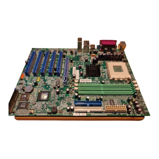
IDE drives . (*: If you use PC3200 DDR DIMM, only DIMM1/2 socket is allowed.) The board is based upon the high performance VIA KT400A (KT-400A Pro and KT-400A) / KT600A (KT-600 Pro) as North Bridge and the VIA VT8235CE... -
Page 5: Package Checklist
KT-400A /KT-600 Dynasty Mainboard Manual Package Checklist If you discover any item below was damaged or lost, please contact your vendor. NOTE: lst Utilities CD that contains patch files, onboard video/au- dio chip drivers, related online help and other useful information can be found in your mainboard package. -
Page 6: Kt-400A Pro / Kt-400A / Kt-600 Pro
Overview KT-400A Pro / KT-400A / KT-600 Pro 1 - 3... -
Page 7: Main Features
KT-400A /KT-600 Dynasty Mainboard Manual Main Features KT-400A Pro and KT-400A support AMD CPU FSB 200/266/333MHz - Athlon XP : |||||1500+ to 3000+, Athlon: |||||||||||||||900MHz to 1.4GHz Duron: |||||||||||||||||900MHz to 1.3GHz KT-600 Pro support AMD CPU FSB 200/266/333/400MHz - Athlon XP : |||||1500+ to 3200+, Athlon: |||||||||||||||900MHz to 1.4GHz... - Page 8 Overview Audio Features Realtek ALC650/655 (dual layout) controller; AC97 LINE_IN, LINE_OUT, MICROPHONE_IN Jack 5.1 audio channel Front audio pinheaders I/O Ports 2 IDE connectors - PIO, Bus Master, Ultra DMA 66/100/133 up to 4 devices 2 serial ports COM1 and COM2 1 parallel port PS/2 mouse and PS/2 keyboard 6 USB ports (KT-600 Pro has 8 USB ports)
-
Page 9: Fic Unique Innovation For Users (Novus) - Enhanced Mainboard Features And System Support
KT-400A /KT-600 Dynasty Mainboard Manual FIC Unique Innovation for Users (NOVUS) - Enhanced Mainboard Features and System Support BIOS Guardian BIOS Guardian effectively acts as a fire-wall against viruses that can attack the BIOS while the system is running and by default is enabled. Please read Page 3-7 for more detail information. -
Page 10: Chapter 2 Installation Procedures
Installation Procedures Chapter 2 Installation Procedures The mainboard has several user-adjustable jumpers on the board that allow you to configure your system to suit your requirements. This chapter contains information on the various jumper settings on your mainboard. To set up your computer, you must complete the following steps: Step 1 - Set system jumpers Step 2 -... -
Page 11: Set System Jumpers
KT-400A /KT-600 Dynasty Mainboard Manual 1). Set System Jumpers NOTE: Users are not encouraged to change the jumper/switch set- tings not listed in this manual. Changing the settings improperly may adversely affect system performance. Clear CMOS The CMOS RAM is powered by the onboard button cell battery. To clear the RTC data: (1) Turn off your computer;... -
Page 12: Bios Anti-Reflash Protect
Installation Procedures BIOS Anti-Reflash Protect The jumper helps users to prevent the BIOS ROM from being overwrit- ten by mistake. FSB Frequency Select These two jumpers allow you to select the front side bus frequency of the board. 2 - 3... -
Page 13: Install Memory Modules
KT-400A /KT-600 Dynasty Mainboard Manual 2). Install Memory Modules 1. Locate DDR DIMM sockets on the mainboard. NOTE: If you use PC3200 DDR DIMM, only DIMM1 and DIMM2 sockets are allowed. 2. Install DDR DIMM straight down into the socket 1 using both hands, then socket 2, and so forth. - Page 14 Installation Procedures CAUTION: 1. The heat sink and fan you installed must be approved by AMD. 2. The mainboard must be placed on a solid place to avoid shaking |||||while install the heat sink and fan on the board. 3. The heat sink must be contact with the CPU top tightly. 4.
-
Page 15: Connect Atx Power
KT-400A /KT-600 Dynasty Mainboard Manual Affix the CPU by pressing the lever downward and locking it beside the socket. 3. Place the fan with heatsink on the CPU top and press down two plastic clips to hook up with the holes on the retention module on two sides. -
Page 16: Install Expansion Cards
Installation Procedures NOTE: Users The CPU installing procedures should be: 1. Insert the CPU (with its fansink and retention module) on the |||||||||||||socket. 2. Connect the 4-pin plug of the power supply 3. Connect the 20-pin plug of the power supply. To remove the processor, please do it in reverse order. - Page 17 KT-400A /KT-600 Dynasty Mainboard Manual 1. Select an available expansion slot. 2. Remove the corresponding slot cover from the computer chassis. Un- screw the mounting screw that secures the slot cover and pull the slot cover out from the computer chassis. Keep the slot cover mounting screw nearby.
-
Page 18: Connect Devices
Installation Procedures 5). Connect Devices Floppy Diskette Drive Connector This connector provides the connection with your floppy disk drive. Insert the floppy ribbon cable (below) onto the floppy connector. The colored stripe (indicated by the arrow head, right) of the ribbon cable must be the same side with the Pin 1. -
Page 19: Fan Connectors
KT-400A /KT-600 Dynasty Mainboard Manual Fan Connectors The two connectors, CPU_FAN, SYSTEM_FAN are linked to the CPU fan, case fan, respectively. Power Connectors The 20-pin male block connector is connected to the ATX power supply. The 4-pin male block connector is for the ATX_12V power use. All two connectors are linked with your ATX power supply. - Page 20 Installation Procedures NOTE: Users that want to use IR port must adjust BIOS feature UART Mode Select to set COM2 at some IR mode upon your IR device. (1) Reset Switch is connected to the reset button. Push this switch to reboot the system instead of turning the power button off and on.
-
Page 21: Spdif_Out Connector
KT-400A /KT-600 Dynasty Mainboard Manual IR is a pinheader that is used for linking with your ID device to allow transmis- sion of data to another system that also supports the IR feature. Speaker is connected with the case speaker. -
Page 22: Cd Audio-In Connectors
Installation Procedures CD Audio-In Connectors The two 1x4 connectors, CD_IN and AUX_IN, are for CD-ROM drive audio analog input use. The pin assignment are: Pin 1 is Left, Pin2 and 3 are GND, Pin 4 is Right. 1394 Connectors (optional) The 2 optional 1394 pinheaders on the board provides you with two connec- tions with the peripherals which own 1394 connectors by an optional bracket with cable (see the figure below). -
Page 23: Ps/2 Keyboard And Mouse Connector
KT-400A /KT-600 Dynasty Mainboard Manual PS/2 Keyboard and Mouse Connector These two 6-pin female (PS/2 keyboard is purple color and PS/2 mouse is green color) connectors are used for your PS/2 keyboard and PS/2 mouse. RJ45 LAN Connector The LAN (RJ45 port) jack is used for the LAN cable plug. -
Page 24: Serial Port Connectors
Installation Procedures Serial Port Connectors COM1/2 (9-pin D-sub male connector with teal color) allow you to connect with your devices that use serial ports, such as a serial mouse or an external modem. Printer Connector This 25-pin D-Sub female burgundy-colored connector is attached to your printer. -
Page 25: Audio I/O Jacks
KT-400A /KT-600 Dynasty Mainboard Manual Audio I/O Jacks LINE_OUT (lime) can be connected to headphones or preferably powered speakers. LINE_IN (light blue) allows tape players or other audio sources to be recorded by your computer or played through the LINE_OUT. MIC_IN (pink) allows microphones to be connected for audio input. -
Page 26: Universal Serial Bus Connectors
NOTE: The LINE_IN, LINE_OUT, MICROPHONE jacks can be used the 5.1-channel audio output with its software tool. For details, please read the FAQ on the web site www.fic.com.tw. Universal Serial Bus Connectors The mainbaord have six USB ports; four USB black jacks that integrated on the edge of the board, the other two USB ports on the board. - Page 27 KT-400A /KT-600 Dynasty Mainboard Manual This Page Left Blank for Note 2 - 18...
-
Page 28: Chapter 3 Bios Setup
BIOS Setup Chapter 3 BIOS Setup The mainboard comes with the chip that Award BIOS that contains the ROM Setup information of your system. (This chip serves as an interface between the processor and the rest of the mainboard components.) This section ex- plains the information contained in the Setup program and tells you how to modify the settings according to your system configuration. -
Page 29: Standard Cmos Setup
KT-400A /KT-600 Dynasty Mainboard Manual Standard CMOS Setup The Standard CMOS Setup screen is displayed above. Each item may have one or more option settings. The system BIOS automatically detects memory size, thus no changes are necessary. Use the arrow keys to highlight the item and then use PgUp or PgDn keys to select the value you want in each item. - Page 30 BIOS Setup Hard Disks This field records the specifications for all non-SCSI hard drives installed in the system. The onboard PCI IDE connectors provide Primary and Sec- ondary channels for connecting up to four IDE hard disks or other IDE devices.
-
Page 31: Advanced Bios Features
KT-400A /KT-600 Dynasty Mainboard Manual Advanced BIOS Features Hard Disk Boot Priority This feature will auto detect all hard disks of bootable device on the system. It also allows users to select hard disk device booting priority. CPU Internal Cache When enabled, improves the system performance. - Page 32 BIOS Setup First/Second/Third Boot Device This feature allows user to select the boot device priority. The options are: Floppy, LS120, Hard Disk, CDROM, ZIP100, USB-FDD, USB-ZIP, USB- CDROM, USB-HDD, LAN, Disabled. Boot Other Device This feature allows user to select the boot device priority. The options are: Enabled, Disabled.
- Page 33 KT-400A /KT-600 Dynasty Mainboard Manual Typematic Delay (Msec) This feature is available only if the item, Typematic Rate Setting, is set at Enabled. Sets the delay time before a character is repeated. The options are: 250, 500, 750, 1000 millisecond.
- Page 34 BIOS Setup BIOS Guardian and Reflash BIOS BIOS Guardian by default is enabled, thus effectively acts as a fire- wall against viruses that can attack the BIOS while the system is running. It must be disabled before reflash BIOS. The steps below show you how to off and on BIOS Guardian when reflash BIOS: 1.
-
Page 35: Advanced Chipset Features
KT-400A /KT-600 Dynasty Mainboard Manual To enable this utility, please proceed as follows: 1. Insert software CD. Select LogoGenie from the Menu and follow the installation instructions. 2. After LogoGenie has been installed, go to Windows Start Box. In Programs Menu, select LogoGenie, then select LogoGenie. - Page 36 BIOS Setup DRAM CAS Latency If the CAS latency of your installed memory medule is 2 Cycle, The selec- tion 2 will enhance system performance. The options are: 1.5, 2, 2.5, 3. Bank Interleave This item allows users to select the bank interleave function of DRAM, when the feature DRAM Timing By SPD set at Disabled.
- Page 37 KT-400A /KT-600 Dynasty Mainboard Manual AGP & P2P Bridge Control AGP Aperture Size It allows you to select the main memory frame size for AGP use. The options list presents all provided possibilities. AGP Mode This feature allows users to select the AGP mode when an AGP add-on card installed.
-
Page 38: Integrated Peripherals
BIOS Setup CPU & PCI Bus Control PCI Master 0 WS Write When enabled, allows a zero-wait-state-cycle delay when the PCI master drive writes data to DRAM. The options are: Enabled, Disabled. VLink 8X Support Enables VLink 8X support. The options are: Enabled, Disabled. PCI Delay Transaction Enable it to abort the current PCI master cycle and accept a new PCI master request, it reaccepts the original PCI master, returns PCI data phase to the... - Page 39 KT-400A /KT-600 Dynasty Mainboard Manual VIA OnChip IDE Device OnChip SATA (KT-600 Pro only) This item allows you to diable the serial ATA controller embedded in South Bridge. The options are: Enabled, Disabled. SATA Mode (KT-600 Pro only) This item allows users to select the serial ATA mode The options are: IDE, Raid.
- Page 40 BIOS Setup Secondary Master/Slave UDMA Allows an automatic configuration of the PCI secondary IDE hard drive (master/slave) mode if Ultra DMA is supported both on the motherboard and the hard disk. The options are: Auto, Disabled. IDE HDD Block Mode Block mode is also called block transfer, multiple commands, or multiple sector read/write.
- Page 41 KT-400A /KT-600 Dynasty Mainboard Manual USB Legacy Support When a USB keyboard is installed, please set at Enabled. The options are: Disabled, Enabled, Auto. SuperIO PCI Device Onboard FDC Controller When enabled, the floppy diskette drive (FDD) controller is activated.
-
Page 42: Power Management Setup
BIOS Setup Power Management Setup ACPI function This item allows you to disable the ACPI function. The options are: Enabled, Disabled. ACPI Suspend Type This item allows you to select ACPI suspend types. The options are: S1(POS), S3 (STR), S1&S3. Power Management Option This item allows you to adjust the power management features. - Page 43 KT-400A /KT-600 Dynasty Mainboard Manual Suspend Mode When disabled, the system will not enter Suspend mode. The specified time option defines the idle time the system takes before it enters Suspend mode. The options are: Disable, 1, 2, 4, 6, 8, 10, 20, 30, 40 Min, 1 Hour.
- Page 44 BIOS Setup AC Loss Auto Restart When the system is shut down owing to the power failure, the system will not be back to power on by itself. This feature allows you to set the system back to which power status of the system when the system power is resumed.
- Page 45 KT-400A /KT-600 Dynasty Mainboard Manual HDD & FDD When it is set at ON, any access happened at hard drives and floppy drives will awake the system. The options are: OFF, ON. PCI Master To set this feature at ON activates that Power Management feautre (PM) wake-up event for the PCI bus master card.
-
Page 46: Pnp/Pci Configurations
BIOS Setup IRQs Activity Monitoring After the time period which you set, the system advances from doze mode to suspend mode in which the CPU clock stops and the screen display is off. At this moment, if the IRQ activity occurs, the system goes back to full- on mode directly. - Page 47 KT-400A /KT-600 Dynasty Mainboard Manual Reset Configuration Data Enabling it to reset the system Extended System Configuration Data (ESCD) when you exit Setup if you have installed a new add-on card and the system reconfiguration has caused such a serious conflict that the operat- ing system can not boot.
-
Page 48: Pc Health Status
BIOS Setup PC Health Status Vcore / 3.3V / +5V / +12V / -12V / -5VSB Standby / Voltage Battery / System Temperature / CPU Temperature / CPU FAN Speed / System FAN Speed These items allow end users and technicians to monitor data provided by the BIOS on this mainboard. -
Page 49: Frequency/Voltage Control
KT-400A /KT-600 Dynasty Mainboard Manual Frequency/Voltage Control Auto Detect DIMM/PCI Clk When enabled, BIOS will detect the PCI slot and DIMM slot. If no any device in, BIOS will auto disable its clock. The options are: Enabled, Disabled. Spread Spectrum This feature is used to select the spread Spectrum range or disable it. -
Page 50: Supervisor/User Password
BIOS Setup Supervisor/User Password To enable the Supervisor/User passwords, select the item from the Standard CMOS Setup. You will be prompted to create your own password. Type your password up to eight characters and press Enter. You will be asked to confirm the password. - Page 51 KT-400A /KT-600 Dynasty Mainboard Manual This Page Left Blank for Note 3 - 24...
Need help?
Do you have a question about the KT-400A and is the answer not in the manual?
Questions and answers