Table of Contents
Advertisement
Advertisement
Table of Contents

Related Manuals for FIC P4MA PRO 533


Summary of Contents for FIC P4MA PRO 533
- Page 1 FIC Mainboard User’s Manual FIC P4MA PRO 533 Version 1.00 - April, 2003...
-
Page 2: Data Protection
FIC product. No Warranty FIC has made every effort to ensure the accuracy of the content of this manual. However, it is possible that it may contain technical inaccuracies or typographical or other errors. - Page 3 FCC-B Radio Frequency Interference Statement This equipment has been tested and found to comply with the limits for a class B digital device, pursuant to part 15 of the FCC rules. These limits are designed to provide reasonable protection against harmful interference when the equipment is operated in a commercial environment.
- Page 4 TRADEMARKS All trademarks used in this manual are the property of their respective owners. Intel and Pentium are registered trademarks of Intel Corporation. PS/2 and OS/2 are registered trademarks of IBM Corporation. Windows 95/98/98SE/ME/2000/XP and Windows NT are registered trademarks of Microsoft.
-
Page 5: Box Contents
Box Contents 1 x FIC Mainboard 1 x User’s manual 1 x Floppy ribbon cable 1 x ATA-66/100/133 IDE ribbon cable 1 x 2 Port USB 2.0 Module 1 x Driver Utilities CD... - Page 8 viii...
-
Page 9: Specifications
Specifications The FIC P4MA PRO 533 mainboard is based around the FIC ProSavageDDR P4M266A chipset, which brings support for high-performance DDR266 SDRAM to the Intel Pentium 4 platform. It is a high ® ® performance, cost-effective and energy efficient SMA chipset for the desktop PC. -
Page 10: Main Memory
Ultra DMA 66/100/133 operation modes • Can connect up to 2 channel for 4 IDE devices Onboard Floppy • 1 x FDD Connector Onboard LAN • FIC VT6103 10/100 Base-T Ethernet PHY Onboard Audio • FIC VT1616 6 channel AC'97 Codec... -
Page 11: Onboard Usb
Onboard USB 2.0/1.1 • 6 x USB 2.0/1.1 ports Onboard I/O Connectors • 2 USB connectors for 4 additional USB 2.0 ports • SPDIF ( optical & coaxial ) connector • Front-panel audio connectors ( Mic and Line Out ) •... - Page 12 FIC P4MA PRO 533 Mainboard...
- Page 14 2-11...
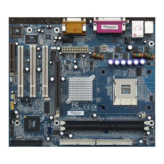
- Page 15 The FIC P4MA PRO 533 mainboard supports the Intel Pentium 4 Willamette/ ® ® Northwood and Celeron processors in the 478 pin package (PGA478). When ® installing the CPU, ensure the CPU has a large-size heatsink and a cooling fan attached on the top to prevent overheating.
- Page 18 The FIC P4MA PRO 533 mainboard provides 2 sockets for 184-pin, 2.5V DDR DIMM modules with 4 memory banks. To operate properly, at least one DIMM module must be installed. You can install PC1600/PC2100 DDR SDRAM modules on the DDR DIMM slots (DDR 1~2).
- Page 20 The FIC P4MA PRO 533 mainboard requires an ATX power supply for powering the system. Before inserting the power supply connector, always make sure that all components are installed properly to ensure that no damage will be caused. ATX 20-Pin Power Connector: ATXPWR This connector is for the ATX power supply.
- Page 21 Mouse Connector: JMS1 Keyboard Connector: JKB1 The FIC P4MA PRO 533 mainboard The mainboard provides a standard PS/ provides a standard PS/2 mouse conn- 2 keyboard connector for attaching a ector for attaching a PS/2 mouse. You PS/2 keyboard. You can plug a PS/2 keyboard can plug a PS/2 mouse directly into directly into this connector.
-
Page 22: Usb Port Connectors
USB Port Connectors The FIC P4MA PRO 533 mainboard provides 2 USB 2.0 ports (plus 2 pinheaders for up to 4 additional USB 2.0 connections; see 2-17). USB-compatible devices can be plugged directly into these ports. Parallel Port Connector: LPT1 The mainboard provides a 25-pin female connector for LPT (parallel port). - Page 23 2-10...
- Page 24 2-11...
- Page 25 2-12...
-
Page 26: Hard Disk Connectors: Ide1 & Ide2
Hard Disk Connectors: IDE1 & IDE2 The FIC P4MA PRO 533 mainboard has a 32-bit Enhanced PCI IDE and Ultra DMA 33/66/100/133 controller that provides PIO mode 0~4, Bus Master, and Ultra DMA 33/66/100/133 functions. You can connect up to four hard disk drive, CD-ROM, LS-120 and other devices. - Page 27 2-14...
- Page 28 Power Button (PW_BN) Connect to a 2-pin switch button. Pressing this button will turn the system power on or off. Reset Switch (RST_SW) The Reset Switch is used to reboot the system rather than turning the power ON/OFF. Avoid rebooting while the HDD is working. You can connect the Reset Switch from the system case to this pin.
- Page 29 2-16...
- Page 30 2-17...
- Page 31 2-18...
- Page 32 2-19...
- Page 33 The FIC P4MA PRO 533 mainboard provides jumpers for setting the mainboard’s functions. This section will explain how to change settings for your mainboard’s functions through the use of the jumpers. 2-20...
- Page 34 2-21...
-
Page 35: Pci Slots
AGP (Accelerated Graphics Port) Slot The AGP4X slot allows you to insert an AGP graphics card. AGP is an interface specification designed for the throughput demands of 3D graphics. It introduces a 66MHz, 32-bit channel for the graphics controller to directly access main memory and provides three levels of throughputs: 1x (266MB/s), 2x (533MB/ s) and 4x (1.07GB/s). -
Page 36: Pci Interrupt Request Routing
PCI Interrupt Request Routing IRQ allows devices to send interrupt signals to the microprocessor. The PCI IRQ pins are typically connected to the PCI bus INT A# ~ INT D# pins as follows: 2-23... - Page 42 Use the arrow keys to highlight the item and use the <PgUp> or <PgDn> keys to select the value you desire for each item.
- Page 43 IDE Primary Master/Slave and Secondary Master/Slave Press <Enter> to enter the sub-menu and the following screen appears: The specifications of your drive must match with the drive table. The hard disk will not work properly if you enter improper information for this category. Select Auto whenever possible.
- Page 44 Virus Warning Set the Virus Warning feature for IDE Hard Disk boot sector protection. If the function is enabled, any attempt to write data into this area will cause a beep and a warning message will be displayed. Settings: Disabled and Enabled. CPU L2 Cache ECC Checking Set the ECC (Error-Correcting Code) feature for Level 2 cache.
- Page 45 Boot Other Device Enable the system to boot from other devices if the system fails to boot from the First/Second/Third boot device. Settings: Enabled and Disabled. Swap Floppy Drive If the system has two floppy drives, choose enable to assign physical drive B to logical drive A and vice-versa.
- Page 46 Typematic Delay (Msec) When Typematic Rate Setting is enabled. This item allows you to select the delay between when the key was first pressed and when the acceleration begins. Settings: 250, 500, 750 and 1000. Security Option Specifies the type of BIOS password protection that is implemented. Settings are described below: MPS Version Control Decides the version of Multiprocessing Specification supported.
- Page 47 The Advanced Chipset Features menu is used for optimizing the chipset functions. Note: Change these settings only if you are familiar with the chipset. AGP Aperture Size This setting controls how much memory space can be allocated to AGP for display purposes. The aperture is a portion of the PCI memory address range dedicated to graphics memory address space.
- Page 48 CPU to PCI POST Write When Enabled, CPU can write up to four words of data to the PCI write buffer before CPU must wait for PCI bus cycle to finish. If Disabled, CPU must wait after each write cycle until PCI bus signals that it is ready to receive more data.
- Page 49 AC97 Audio Auto allows the mainboard to detect whether an audio device is used. If the device is detected, the onboard FIC AC’97 (Audio Codec’97) controller will be enabled; if not, it is disabled. Disable the controller if you want to use other controller cards to connect an audio device. Setting options: Auto and Disabled.
- Page 50 3-14...
-
Page 51: Superio Device
SuperIO Device Press <Enter> to enter the sub-menu and the following screen appears: Onboard FDC Controller Enable the onboard floppy controller. Select “Enabled” when you have installed a floppy disk drive. Settings: Enabled and Disabled. Onboard Serial Port 1/2 Set the base I/O port address and IRQ for the onboard serial port A/serial port B. - Page 52 SPP : Standard Parallel Port EPP : Enhanced Parallel Port ECP : Extended Capability Port ECP + EPP: Extended Capability Port + Enhanced Parallel Port EPP Mode Select Select the Enhance Parallel Port mode. Settings: EPP1.9 and EPP1.7. ECP Mode Use DMA ECP utilises a DMA channel.
- Page 53 3-17...
- Page 54 3-18...
- Page 55 3-19...
- Page 56 3-20...
- Page 57 3-21...
- Page 58 3-21...
- Page 59 3-23...
- Page 60 3-24...
- Page 61 DRAM Clock The chipset supports synchronous and asynchronous mode between host clock and DRAM clock frequency. Settings: By SPD, 100MHz and 133MHz. DRAM Timing This setting determines whether DRAM timing is configured by reading the contents of the SPD (Serial Presence Detect) EPROM on the DRAM module. Selecting Yes makes SDRAM Cycle Length and Bank Interleave automatically determined by BIOS according to the configurations on the SPD.
- Page 62 Active to Precharge (Tras) Set the time from active back to precharge state. Settings: 5T and 6T. Active to CMD (Trcd) Set the time from active state to command state. Settings: 2T and 3T. DRAM Command Rate This setting controls the DRAM command rate. Selecting 1T allows DRAM signal controller to run at 1T (T=clock cycles) rate.
- Page 63 Spread Spectrum When the motherboard’s clock generator pulses, the extreme values (spikes) of the pulses creates EMI (Electromagnetic Interference). The Spread Spectrum function reduces the EMI generated by modulating the pulses so that the spikes of the pulses are reduced to flatter curves. If you do not have any EMI problems, leave the setting at Disabled for optimal system stability and performance.
- Page 64 3-28...
- Page 65 3-29...
- Page 66 Type the password, up to eight characters in length, and press <Enter>. The password typed now will clear any previously set password from CMOS memory. You will be prompted to confirm the password. Re-type the password and press <Enter>. You may also press <Esc> to abort the selection and not enter a password.
- Page 67 3-31...
- Page 68 3-32...
- Page 69 3-33...
-
Page 71: Driver Utilities Cd Content
Driver Utilities CD Content Getting Started The FIC P4MA PRO 533 mainboard includes a Driver Utilities CD which contains driver utilities and software to enhance the performance of the mainboard. Please check that you have this CD in your retail box. If the CD is missing in your retail box, please contact your local dealer for the CD. -
Page 73: Smart 5.1-Intelligent 6 Channel Audio
Smart 5.1-Intelligent 6 Channel Audio... - Page 74 Smart 5.1-Intelligent 6 Channel Audio...
- Page 75 Smart 5.1-Intelligent 6 Channel Audio...
- Page 76 Smart 5.1-Intelligent 6 Channel Audio Channel...
- Page 77 Smart 5.1-Intelligent 6 Channel Audio...
- Page 78 Smart 5.1-Intelligent 6 Channel Audio...
- Page 79 Smart 5.1-Intelligent 6 Channel Audio...
-
Page 80: Hyper-Threading Technology
Hyper – Threading Technology Intel® Hyper-Threading Technology is a type of simultaneous multi-threading technology (SMT). Multiple threads of software applications are able to be run concurrently on one processor. Hyper-Threading Technology makes a single physical processor simulate two logical processors which enhance the executing performance especially in operating systems that handle multiple applications simultaneously.
Need help?
Do you have a question about the P4MA PRO 533 and is the answer not in the manual?
Questions and answers