
Related Manuals for FIC KT-748


Summary of Contents for FIC KT-748
- Page 1 KT-748 MAINBOARD MANUAL DOC No.: M03403 Rev. : A0 Date : 6, 2003 Part No. : 25-11663-00...
-
Page 2: Handling Precautions
Notice Handling Precautions Warning: 1. Static electricity may cause damage to the integrated circuits on the motherboard. Before handling any motherboard outside of its protective packaging, ensure that there is no static electric charge in your body. 2. There is a danger of explosion if the battery is incorrectly replaced. -
Page 3: Table Of Contents
Chapter 1 Overview Package Checklist ................. 1-2 The KT-748 Mainboard ............. 1-3 Main Features ................1-4 FIC Unique Innovation for Users (NOVUS) - Enhanced Mainboard Features and System Support ..... 1-5 Chapter 2 Installation Procedures 1). Set System Jumpers ..............2-2 Clear CMOS .............. - Page 4 KT-748 Mainboard Manual Chapter 3 BIOS Setup CMOS Setup Utility ..............3-1 Standard CMOS Setup ..............3-2 Advanced BIOS Features .............. 3-4 Advanced Chipset Features ............3-7 Integrated Peripherals ..............3-9 Power Management Setup ............. 3-12 PnP/PCI Configurations ..............3-16 PC Health Status ................
-
Page 5: Chapter 1 Overview
Overview Chapter 1 Overview The new mainboard is an ATX sized motherboard supporting the latest gen- eration of AMD processors at industry leading speeds. By utilizing DDR ( ® Double Data Rate ) transfer rate effectively reaches Front Side Bus speeds of 200/266/333/400 MHz. -
Page 6: Package Checklist
KT-748 Mainboard Manual Package Checklist If you discover any item below was damaged or lost, please contact your vendor. NOTE: lst Utilities CD that contains patch files, onboard video/au- dio chip drivers, related online help and other useful information can be found in your mainboard package. -
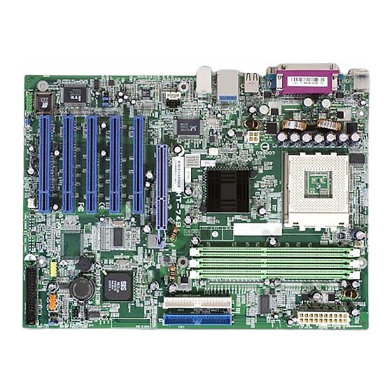
Page 7: The Kt-748 Mainboard
Overview The KT-748 Mainboard 1 - 3... -
Page 8: Main Features
KT-748 Mainboard Manual Main Features Duron: 900 - 1.3 GHz at FSB 200 MHz Athlon : 900 - 1.4 GHz at FSB 200/266 MHz Athlon XP: Polomino Core: 1500+ - 2100+ at FSB 266 MHz Thorughtbred Core: 1700+ - 2600+ at FSB 266 MHz... -
Page 9: Fic Unique Innovation For Users (Novus) - Enhanced Mainboard Features And System Support
10/100/1000 Ethernet ® IEEE 1394 Ports (optional) VT6307L; 2 ports; 1 bracket with cable FIC Unique Innovation for Users (NOVUS) - Enhanced Mainboard Features and System Support LogoGenie A user friendly GUI supporting Windows 95/98SE (not Windows 2000/ NT/ME/XP), LogoGenie allows you to customize, create or select a Logo which will be displayed when the system is booting. - Page 10 KT-748 Mainboard Manual BIOS Guardian BIOS Guardian effectively acts as a fire-wall against viruses that can at- tack the BIOS while the system is running and by default is enabled. WARNING: BIOS Guardian must be disabled before reflash BIOS. NOTE: Please read Page 3-6 for detail information.
-
Page 11: Chapter 2 Installation Procedures
Installation Procedures Chapter 2 Installation Procedures The mainboard has several user-adjustable jumpers on the board that allow you to configure your system to suit your requirements. This chapter contains information on the various jumper settings on your mainboard. To set up your computer, you must complete the following steps: Step 1 - Set system jumpers Step 2 -... -
Page 12: Set System Jumpers
KT-748 Mainboard Manual 1). Set System Jumpers NOTE: Users are not encouraged to change the jumper/switch set- tings not listed in this manual. Changing the settings improperly may adversely affect system performance. Clear CMOS The CMOS RAM is powered by the onboard button cell battery. To clear the RTC data: (1) Turn off your computer;... -
Page 13: Bios Anti-Reflash Protect
Installation Procedures BIOS Anti-Reflash Protect The jumper helps users to prevent the 64K boot block table area in the BIOS ROM from being overwritten by mistake. 2). Install Memory Modules 1. Locate DDR DIMM sockets on the mainboard. 2 - 3... -
Page 14: Install The Cpu
KT-748 Mainboard Manual 2. Install DDR DIMM straight down into the socket 1 using both hands, then socket 2, and so forth. 3. The clip on both ends of the socket will close up to hold the DDR DIMM in place when the DDR DIMM reaches the socket bottom. - Page 15 Installation Procedures 1. Swing the lever upword to 90 degree. 2. Install the CPU and make sure the the pin 1 orientation by aligning the socket corner marking with the socket corner closest to the lever tip. Do not insert the CPU by force. Make sure the processor is fully inserted into the socket on all sides.
-
Page 16: Connect Atx Power
KT-748 Mainboard Manual Affix the CPU by pressing the lever downward and locking it beside the socket. 3. Place the fan with heatsink on the CPU top and press down two plastic clips to hook up with the holes on the retention module on two sides. -
Page 17: Install Expansion Cards
Installation Procedures NOTE: 1. Insert the CPU (with fansink and retention module) on socket. 2. Connect the 4-pin plug of the power supply 3. Connect the 20-pin plug of the power supply. To remove the processor, please do it in reverse order. 4). - Page 18 KT-748 Mainboard Manual 1. Select an available expansion slot. 2. Remove the corresponding slot cover from the computer chassis. Un- screw the mounting screw that secures the slot cover and pull the slot cover out from the computer chassis. Keep the slot cover mounting screw nearby.
-
Page 19: Connect Devices
Installation Procedures 5). Connect Devices Floppy Diskette Drive Connector This connector provides the connection with your floppy disk drive. Insert the floppy ribbon cable (below) onto the floppy connector. The colored stripe (indicated by the arrow head, right) of the ribbon cable must be the same side with the Pin 1. -
Page 20: Fan Connectors
KT-748 Mainboard Manual Fan Connectors The two connectors, CPU_FAN, SYSTEM_FAN are linked to the CPU fan, case fan, respectively. CHIP_FAN can be used with North Bridge chip fan. Power Connectors The 20-pin male block connector is connected to the ATX power supply. The 4-pin male block connector is for the ATX_12V power use. -
Page 21: Front Panel Block Connector
Installation Procedures Front Panel Block Connector This block connector includes the connectors for linking with Power LED (3-pin), HDD LED, power button, power/sleep/ message waiting button, reset buttonon the front panel of the system case. Please identify polarities of plug wires for the case speaker and LEDs. -
Page 22: Spdif_In/Spdif_Out Connector
KT-748 Mainboard Manual (4) Power Button is connected with power button. Push this switch allows the system to be turned on and off rather than using the power supply button. IR is a pinheader that is used for linking with your ID device to allow transmis- sion of data to another system that also supports the IR feature. -
Page 23: Cd Audio-In Connectors
Installation Procedures CD Audio-In Connectors The two 1x4 connectors, CD_IN and AUX_IN, are for CD-ROM drive audio analog input use. The pin assignment are: Pin 1 is Left, Pin2 and 3 are GND, Pin 4 is Right. 1394 Connectors (optional) The 2 optional 1394 pinheaders on the board provides you with two connec- tions with the peripherals which own 1394 connectors by an optional bracket with cable (see the figure below). -
Page 24: Ps/2 Keyboard And Mouse Connector
KT-748 Mainboard Manual PS/2 Keyboard and Mouse Connector These two 6-pin female (PS/2 keyboard is purple color and PS/2 mouse is green color) connectors are used for your PS/2 keyboard and PS/2 mouse. RJ45 LAN Connector The LAN (RJ45 port) jack is used for the LAN cable plug. -
Page 25: Serial Port Connectors
Installation Procedures Serial Port Connectors COM1/2 (9-pin D-sub male connector with teal color) allow you to connect with your devices that use serial ports, such as a serial mouse or an external modem. Printer Connector This 25-pin D-Sub female burgundy-colored connector is attached to your printer. -
Page 26: Audio I/O Jacks
KT-748 Mainboard Manual Audio I/O Jacks LINE_OUT (lime) can be connected to headphones or preferably powered speakers. LINE_IN (light blue) allows tape players or other audio sources to be recorded by your computer or played through the LINE_OUT. MIC_IN (pink) allows microphones to be connected for audio input. -
Page 27: Universal Serial Bus Connectors
NOTE: The LINE_IN, LINE_OUT, MICROPHONE jacks can be used the 5.1-channel audio output with its software tool. For details, please read the FAQ on the web site www.fic.com.tw. Universal Serial Bus Connectors The mainbaord have six USB ports; four USB black jacks that integrated on the edge of the board, the other two USB ports on the board. -
Page 28: Audio Channel Feature
KT-748 Mainboard Manual 5.1 Audio Channel Feature The 5_1_AUDIO sound feature are offered via the pinheaders with an optional A73 bracket with ribbon cable. The pinheaders pin assignments are shown below left. When use the daughter board, plug in the LINE_OUT jack for the front speaker audio output (right and left). -
Page 29: Chapter 3 Bios Setup
BIOS Setup Chapter 3 BIOS Setup The mainboard comes with the chip that Award BIOS that contains the ROM Setup information of your system. (This chip serves as an interface between the processor and the rest of the mainboard components.) This section ex- plains the information contained in the Setup program and tells you how to modify the settings according to your system configuration. -
Page 30: Standard Cmos Setup
KT-748 Mainboard Manual Standard CMOS Setup The Standard CMOS Setup screen is displayed above. Each item may have one or more option settings. The system BIOS automatically detects memory size, thus no changes are necessary. Use the arrow keys to highlight the item and then use PgUp or PgDn keys to select the value you want in each item. - Page 31 BIOS Setup Hard Disks This field records the specifications for all non-SCSI hard drives installed in the system. The onboard PCI IDE connectors provide Primary and Sec- ondary channels for connecting up to four IDE hard disks or other IDE devices.
-
Page 32: Advanced Bios Features
KT-748 Mainboard Manual Advanced BIOS Features Virus Warning This feature starts the virus scan tool to detect if boot virus in boot sector of the first hard disk drive when booting up. The options are: Enabled, Disabled. CPU Internal Cache This controls the status of the processor’s internal cache area. - Page 33 BIOS Setup Boot Other Device Enable the system to boot from other devices if the system fails to boot from the devices that selected from above three features. The options are: Enabled, Disabled. Swap Floppy Drive Allows you to switch the order in which the operating system accesses the floppy drives during boot up.
- Page 34 KT-748 Mainboard Manual MPS Version Control For OS When two CPUs onboard (not this board) this feature allows you to select MPS (Multi-Processor Spec.) version control for OS when logo test executes. The options are: 1.1, 1.4. OS Select For DRAM > 64MB If your operating system (OS) is OS/2, select the option OS2.
-
Page 35: Advanced Chipset Features
BIOS Setup The steps below show you how to off and on BIOS Guardian when reflash BIOS: 1. Press Del key while booting. Go to CMOS Setup Utility menu. 2. Go to Advanced BIOS Features submenu. 3. Set the feature BIOS Guardian at Disabled. 4. - Page 36 KT-748 Mainboard Manual Advanced DRAM Control 1 Auto Configuration The feature allows users to decide the performance of the memory CAS/ LAS cycle. The options are: Normal, Performance. DDR SDRAM CAS Latency This feature allows users to set the DDR SDRAM CAS latency timing cycle, when the above feature set at Performance.
-
Page 37: Integrated Peripherals
BIOS Setup Video RAM Cacheable When enabled, allows the video RAM area to be cacheable. The options are: Enabled, Disabled. Integrated Peripherals SIS OnChip IDE Device Internal PCI/IDE This item allows users to disable either or both PCI and IDE channels. The options are: Disabled, Primary, Secondary, Both. - Page 38 KT-748 Mainboard Manual IDE Secondary Master/Slave PIO Allows an automatic or a manual configuration of the PCI secondary IDE hard drive (master/slave) mode. The options are: Auto, Mode 0, Mode 1, Mode 2, Mode 3, Mode 4. Primary Master/Slave UDMA...
- Page 39 BIOS Setup Onboard Serial Port 1/2 If the serial port 1/2 uses the onboard I/O controller, you can modify your serial port parameters.The options are: 3F8/IRQ4, 3E8/IRQ4, 2F8/IRQ3, 2E8/ IRQ3, Disabled. UART Mode Select Allows you to select the IR modes if the serial port 2 is used as an IR port. Set at Standard, if you use COM2 as the serial port as the serial port, instead as an IR port.
-
Page 40: Power Management Setup
KT-748 Mainboard Manual Onboard 1394 Device It allows users to disable the onboard 1394 feature. The options are: Enabled, Disabled. AC97 AUDIO This feature auto detects if you use a card that with a CODEC to enable or disable the AC97 audio function. The options are: Enabled, Disabled. - Page 41 BIOS Setup Power Management This item allows you to adjust the power management features. Select User Define for configuring your own power management features. Min Saving initiates all predefined timers in their minimum values. Max Saving, on the other hand, initiates maximum values. The options are: User Define, Min Saving, Max Saving.
- Page 42 KT-748 Mainboard Manual HDD Off After The option lets the BIOS turn the HDD motor off when system is in Sus- pend mode. Selecting 1 Min..15 Min allows you define the HDD idle time before the HDD enters the Power Saving Mode.
- Page 43 BIOS Setup Month Alarm/Day of Month Alarm/Time (hh:mm:ss) Alarm This feature allows you to set the time of the alarm starts. ** Reload Global Timer Events ** Primary IDE When the primary master/slave HDD is working, the system timer will be reloaded and the system will not be into the suspend mode.
-
Page 44: Pnp/Pci Configurations
KT-748 Mainboard Manual PnP/PCI Configurations Reset Configuration Data Enabling it to reset the system Extended System Configuration Data (ESCD) when you exit Setup if you have installed a new add-on card and the system reconfiguration has caused such a serious conflict that the operat- ing system can not boot. -
Page 45: Pc Health Status
BIOS Setup PC Health Status Shutdown Temperature This feature helps to shutdown the system when the system temperature is as high as the selected temperature to prevent from the overheat problem. The option list presents all the temperatures that supported by the board and Disabled. -
Page 46: Frequency/Voltage Control
KT-748 Mainboard Manual Frequency/Voltage Control Auto Detect DIMM/PCI Clk When enabled, BIOS will detect the PCI slot and DIMM slot. If no any device in, BIOS will auto disable its clock. The options are: Enabled, Disabled. Spread Spectrum This item reduces the EMI (Electromagnetic Interference) generated by modulating the pulses so that the spikesof the pulses are reduced to flatter curves. -
Page 47: Load Fail-Safe Defaults
BIOS Setup Load Fail-Safe Defaults This submenu is selected to diagnose the problem after the computer boots, if the computer will not boot. These settings do not give optimal performance. Load Optimized Defaults This submenu is selected for default settings which provide the best system performance. -
Page 48: Exit Without Saving
KT-748 Mainboard Manual Exit without Saving If you select this feature, the following message will appear at the center of the screen to allow you to exit the setup utility without saving CMOS modifications: Quit Without Saving (Y/N)? 3 - 20...
Need help?
Do you have a question about the KT-748 and is the answer not in the manual?
Questions and answers