Table of Contents
Advertisement
The VT-501 has several user-adjustable jumpers on the board that allow you to
configure your system to suit your requirements. This chapter contains
information on the various jumper settings on your mainboard.
To set up your computer, you should follow these installation steps:
Step 1 -
Set system jumpers
Step 2 -
Install DRAM and SDRAM modules
Step 3 -
Install the CPU
Step 4 -
Install expansion cards
Step 5 -
Connect cables and power supply
Step 6 -
Set up BIOS feature (Please read Chapter Three.)
Installation Procedures
Chapter 2
11
Advertisement
Table of Contents

Related Manuals for FIC VT-501


Summary of Contents for FIC VT-501
- Page 1 Chapter 2 Installation Procedures The VT-501 has several user-adjustable jumpers on the board that allow you to configure your system to suit your requirements. This chapter contains information on the various jumper settings on your mainboard. To set up your computer, you should follow these installation steps:...
-
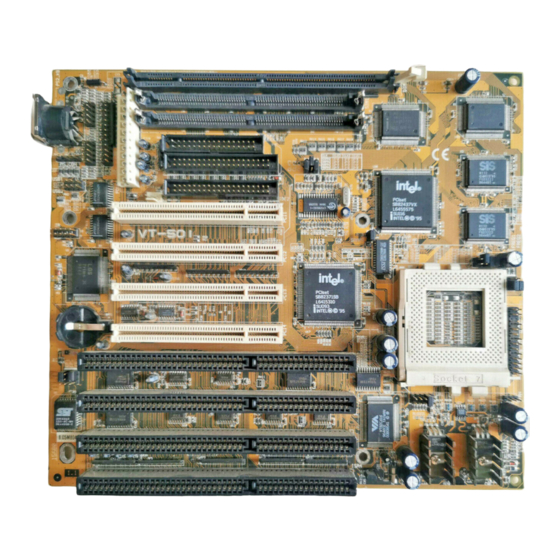
Page 2: Mainboard Layout
VT-501 Mainboard Manual Mainboard Layout... -
Page 3: Set System Jumpers
Installation Procedures 1). Set System Jumpers Jumpers Jumpers are used to select the operation modes for your system. Some jumpers on the board have three metal pins with each pin representing a different function. To “ set” a jumper, a black cap containing metal contacts is placed over the jumper pin/s according to the required configuration. - Page 4 VT-501 Mainboard Manual Clear Password: CPW This jumper allows you to set the password configuration to “ Enabled” or “ Disabled” . You may need to enable this jumper if you forget your password. Flash EPROM Type: EP1, EP2 and EP3...
-
Page 5: Install System Memory
The VT-501’s RAM is comprised of two industry standard 72-pin Single In- line Memory Modules (SIMMs) and one 168-pin Dual In-line Memory Module (DIMM). The SIMM socket is able to support from 8 to 128MB FPM (Fast Page Mode) and EDO (Extended Data Out) DRAM. - Page 6 VT-501 Mainboard Manual DRAM and SDRAM Configuration TOTAL SIMM DIMM MEMORY BANK0 (72-PIN X 2) BANK1 (168-PIN X 1) 4MB & 4MB 16MB 8MB & 8MB 4MB & 4MB 24 MB 8MB & 8MB 32 MB 8MB & 8MB 16MB 16MB &...
-
Page 7: Install Simms
Installation Procedures Install SIMMs Complete the following procedures to install SIMMs: CAUTION : Always turn the system power off before installing or removing any device; and see “Handling Precautions” at the start of this manual. 1. Locate the SIMM slots on the mainboard. (See figure below.) NOTE : BANK 0 and BANK 1 can use different type SIMMs - but you must populate each memory bank with the same type of SIMM. -
Page 8: Install Dimm
VT-501 Mainboard Manual Install DIMM Complete the following procedures to install DIMMs: 1. Locate the DIMM slot on the mainboard. (See figure below.) 2. Insert the DIMM straight down onto the DIMM slot with both hands carefully until the clips on the ends of the slot close up to hold the DIMM firmly. -
Page 9: Cache Memory
Installation Procedures Cache Memory The VT-501 comes with onboard 256KB/512KB synchronous 3V Pipeline Burst SRAM. Please note that for 256KB secondary cache, M2 and M3 should be mounted with 32Kx32 Pipeline Burst SRAM. (Please refer to your dealer for the 512KB... - Page 10 VT-501 Mainboard Manual 256/512KB Cache SRAM NOTE : Use the correct chips for the amount of cache memory you want to add. Install both the correct Cache and Tag SRAM.
-
Page 11: Install The Cpu
Installation Procedures 3). Install the CPU The CPU module resides in the Zero Insertion Force (ZIF) socket on the mainboard. CAUTION : 1. Always turn the system power off before installing or removing any device. 2. Always observe static electricity precautions. See “Handling Precautions”... - Page 12 VT-501 Mainboard Manual CPU External Clock (BUS) Frequency: CLK1, CLK2, and CLK3 The table below shows the jumper settings for the different CPU speed configurations. CPU to Bus Frequency Ratio: FREQ1 and FREQ2 These two jumpers are used in combination to decide the ratio of the internal...
- Page 13 Installation Procedures Intel Pentium CPUs Frequency...
- Page 14 VT-501 Mainboard Manual Voltage...
- Page 15 Installation Procedures AMD-K5 CPUs Frequency Note : * This CPU had not been tested when this manual was printed.
- Page 16 VT-501 Mainboard Manual Voltage...
- Page 17 Installation Procedures Cyrix 6x86 CPUs Frequency Note : * This CPU had not been tested when this manual was printed.
- Page 18 VT-501 Mainboard Manual Voltage Note : * This CPU had not been tested when this manual was printed.
- Page 19 Installation Procedures IBM 6x86 CPUs Frequency Note : * This CPU had not been tested when this manual was printed.
- Page 20 VT-501 Mainboard Manual Voltage Note : * This CPU had not been tested when this manual was printed.
-
Page 21: Installation Of Cyrix (Or Ibm) 6X86 Cpu Fan
Installation Procedures Installation of Cyrix (or IBM) 6x86 CPU Fan CAUTION : When you install a Cyrix (or IBM) 6x86 CPU fan, please pay attention to the direction of the air flow. Make sure the air flow is in the direction of the regulator;... -
Page 22: Install Expansion Cards
VT-501 Mainboard Manual 4). Install Expansion Cards Your VT-501 features four 16-bit ISA Bus and four 32-bit PCI Bus expansion slots. This section describes how to connect an expansion card to one of your system’s expansion slots. Expansion cards are printed circuit boards that, when connected to the mainboard, increase the capabilities of your system. - Page 23 Installation Procedures Holding the edge of the peripheral card, carefully align the edge connector with the expansion slot. (See figure below.) Push the card firmly into the slot. Push down on one end of the expansion card, then the other. Use this “ rocking” motion until the add-in card is firmly seated inside the slot.
-
Page 24: Connect Cables And Power Supply
VT-501 Mainboard Manual 5). Connect Cables and Power Supply Keyboard Connector: AT_KB This 5-pin female connector is connected to your keyboard. Serial Port Connector: COM1 and COM2 These two 10-pin male connectors allow you to connect with your devices that take serial ports, such as a serial mouse or a modem. - Page 25 Installation Procedures PS/2 Mouse Connector: MS_CON This connector is connected to your PS/2 mouse. CPU Fan Connector: FAN This connector is linked to the CPU fan.
- Page 26 VT-501 Mainboard Manual Floppy Diskette Drive Connector: FLOPPY This 34-pin block connector connects to your floppy diskette drive (FDD) using the cable that is provided with this mainboard.
- Page 27 Installation Procedures Block Connector This block connector concludes : PW_LED, KB_LOCK, TB_LED, SP_SW, SPK, SP_LED, IDE_LED, RPW_SW, and RST connectors. Item Connector Pin Type Feature PW_LED 2-pin male indicates the system power status KB_LOCK 2-pin male allows the keyboard to access the system TB_LED 2-pin male...
- Page 28 VT-501 Mainboard Manual Infrared Connector: IR This 10-pin male connector is used for connecting to the serial infrared (SIR) port and allows transmission of data to another system which also supports the SIR feature. Power Block Connector: POWER This 12-pin block connector is used for connecting to your standard 5V power supply.
- Page 29 Installation Procedures IDE HDD Device Connector: PRIMARY and SECONDARY This two 40-pin block connectors are used for your IDE hard disks. It you have one IDE hard disk, connect it to the PRIMARY connector using the IDE HDD flat cable provided with the mainboard. The BIOS auto detection sets it to be a “...
- Page 30 VT-501 Mainboard Manual Remote Power Connector: RPW_CON This 3-pin male connector allows you to enable or disable the system power if the RPW_SW is on or off. (This allows you to adapt the remote power switch feature. Please contact your dealer for further information.) Universal Serial Bus Connectors: USB1 and USB2 This connects to the port that allows you to attach a USB hub.
- Page 31 Installation Procedures...
Need help?
Do you have a question about the VT-501 and is the answer not in the manual?
Questions and answers