
Related Manuals for FIC P4M-865G MAX


Summary of Contents for FIC P4M-865G MAX
- Page 1 8 6 5 Dynas t y MAINBOARD MANUAL P4M-865G MAX P4M-865PE MAX P4M-865G Ultra P4M-865PE Ultra P4M-865P Ultra DOC No.: M03106 Rev. : A0 Date : 5, 2003 Part No. : 25-10655-00...
- Page 2 Notice Handling Precautions Warning: 1. Static electricity may cause damage to the integrated circuits on the motherboard. Before handling any motherboard outside of its protective packaging, ensure that there is no static electric charge in your body. 2. There is a danger of explosion if the battery is incorrectly replaced.
-
Page 3: Table Of Contents
P4M-865G Ultra P4M-865PE Ultra P4M-865P Ultra ................. 1-3 Main Features ................1-4 FIC Unique Innovation for Users (NOVUS) - Enhanced Mainboard Features and System Support ....1-6 Chapter 2 Installation Procedures 1). Set System Jumpers ..............2-2 Clear CMOS ..............2-2 BIOS Protect .............. - Page 4 865 Dynasty Mainboard Manual Audio I/O Jacks ..............2-17 Front Audio Connector ............. 2-17 CRT Connector ..............2-18 Universal Serial Bus Connectors ........2-18 Chapter 3 BIOS Setup CMOS Setup Utility ............... 3-1 Standard CMOS Setup ..............3-2 Advanced BIOS Features .............. 3-4 Advanced Chipset Features ............
- Page 5 8 6 5 Dynas t y ® Pentium 4 with NOTE: The information in this document are subject to change without further notice. Part Number: 25-10655-40...
- Page 6 EZ Guide Intel 865 Series...
-
Page 7: Package Checklist
Package Checklist Mainboard Manual 865 Dynasty EZ Guide FDD cable Drivers CD ATA-100 cable I/O shielding USB cable Serial ATA cable (optional) 1394 bracket with cable (optional) Before Start Warning: 1. Static electricity may cause damage to the integrated cir- cuits on the motherboard. - Page 8 Step 1 - Install CPU 1. Swing the lever upword to 90 degree. 2. Install the CPU and make sure the the pin 1 orientation by aligning the socket corner marking with the socket corner closest to the lever tip. Do not insert the CPU by force.
- Page 9 Step 2 - Install Memory Module Step 2 - Install Memory Module 1. Locate DDR DIMM sockets on the mainboard. 2. Install DDR DIMM straight down into the socket 1 using both hands, then socket 2, and so forth. 3. The clip on both ends of the socket will close up to hold the DDR DIMM in place when the DDR DIMM reaches the socket bottom.
- Page 10 Step 3 - Install Mainboard Warning: 1. Excessive torque may damage the mainboard. When using an electric screwdriver on the mainboard, make sure that the torque is set to the allowable range of 5.0 ~ 8.0kg/cm. 2. Be aware of the shape edges in the case while installing board.
- Page 11 Front and Rear Panel Note: The chassis might not be the same as yours. The specifica- tion here is only for reference. Generally, most cases are simi- lar.
-
Page 12: Floppy Drive
1. Locate floppy drive frame and storage on the chassis. 2. Place the drive from the front panel side into the frame. 3. Affix the drive on the frame by screws. 4. Connect the floppy cable and power cable. http://www.fic.com.tw... - Page 13 Step 4 - Install Devices (continued) CD/DVD Drive 1. Locate CD/DVD drive frame and storage on the chassis. 2. Place the drive from the front panel side into the frame. 3. Affix the drive on the frame by screws. 4. Connect the IDE cable and power cable.
-
Page 14: Hard Disk Drive
Step 4 - Install Devices Hard Disk Drive 1. Locate hard drive frame and storage on the chassis. 2. Place the hard disk drive from the rear of the frame as the arroaw head indciated. 3. Affix the drive on the frame by screws. - Page 15 Step 5 - Install Add-on Card Warning: Make sure to unplug the power supply when adding or remov- ing expansion cards or other system components. Failure to do so may cause severe damage to both the mainboard and expansion cards. 1.
-
Page 16: Atx Power
Step 6 - Connect Wires Use the USB bracket with cable to install it on the rear panel. The pin defini- tions of the USB pinheaders (positions in the white rectangle in the below right figure) are shown in the table below: ATX Power The 20-hole power plug (top right) is connected to the ATX power 20-pin... -
Page 17: Serial Ata
Step 6 (continued) Serial ATA Use the optional SATA cable to con- nect to the hard drives (lower one is a SATA data cable) and link with the power supply (upper one is a SATA power cable). The pin definitions of the SATA pinheaders (positions in the white rect- angle in the right figure) are shown in the... - Page 18 Step 7 - Set System Jumpers Clear CMOS Warning: Please disconnect the ATX power cable before set this jumper and connect the ATX power cable after clear CMOS. BIOS Protect Enable The jumper is used to make sure that the system BIOS can boot up when it is enabled (default setting).
- Page 19 Step 8 - Assembly Case Place the cover on the chas- sis and secure the screws on the cover either by a screw driver or by fingers to tighten them up. Step 9 - Link Peripherals Link peripheral devices to your system via rear/front panel.
- Page 20 The item provides you with some information about the fea- tures and drivers. Reading it will be helpful on installation. Software Bundle The item provides you with some useful software tools to assist you to man- age your computer system. http://www.fic.com.tw...
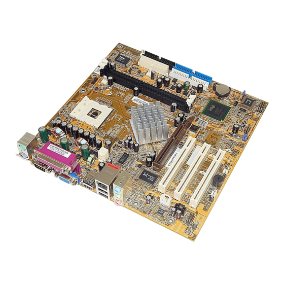
- Page 21 Chapter 1 Overview Overview The new microATX, 478-pin 1stMainboard supports a full range of the latest ® generation Intel Pentium 4 processors. The leading edge Intel chipset ® ® ® was designed for coworking with Pentium 4 (up to 3.06 GHz) in the 478-pin ®...
- Page 22 865 Dynasty Mainboard Manual Package Checklist If you discover any item below was damaged or lost, please contact your vendor. NOTE: lst Utilities CD that contains patch files, onboard video/au- dio chip drivers, related online help and other useful information can be found in your mainboard package.
-
Page 23: P4M-865G Max P4M-865Pe Max
Overview P4M-865G MAX P4M-865PE MAX P4M-865G Ultra P4M-865PE Ultra P4M-865P Ultra 1 - 3... -
Page 24: Main Features
865 Dynasty Mainboard Manual Main Features Celeron 1.4 G to 2.4 GHz and up* (FSB 400) 2.0 to 2.8 GHz and up* (FSB 533) / 3.06 GHz and up* (FSB 800) (*: not tested yet) Chipset North Bridge: Intel 865G/PE/P ®... - Page 25 Overview I/O Ports 2 IDE connectors - PIO, Bus Master, Ultra DMA 66/100 up to 4 devices 1 serial port COM1 1 parallel port; 1 CRT port PS/2 mouse and PS/2 keyboard 8 USB 1.1/2.0 ports RTL 8100BL ® IEEE 1394 Ports (optional) Agere FW323 2 ports 1 bracket with cable...
-
Page 26: Fic Unique Innovation For Users (Novus) - Enhanced Mainboard Features And System Support
865 Dynasty Mainboard Manual FIC Unique Innovation for Users (NOVUS) - Enhanced Mainboard Features and System Support LogoGenie A user friendly GUI supporting Windows 95/98SE (not Windows 2000/ NT/ME/XP), LogoGenie allows you to customize, create or select a Logo which will be displayed when the system is booting. -
Page 27: Chapter 2 Installation Procedures
Chapter 2 Installation Procedures Installation Procedures The mainboard has several user-adjustable jumpers on the board that allow you to configure your system to suit your requirements. This chapter contains information on the various jumper settings on your mainboard. To set up your computer, you must complete the following steps: Step 1 - Set system jumpers Step 2 -... -
Page 28: Set System Jumpers
865 Dynasty Mainboard Manual 1). Set System Jumpers Jumpers are used to select the operation modes for your system. Some jump- ers on the board have three metal pins with each pin representing a different function. A 1 is written besides pin 1 on jumpers with three pins. To set a jumper, a black cap containing metal contacts is placed over the jumper pin/s according to the required configuration. -
Page 29: Bios Protect
Installation Procedures BIOS Protect The jumper helps users to prevent the 64K boot block table area in the BIOS ROM from being overwritten by mistake. 2 - 3... -
Page 30: Install Memory Modules
865 Dynasty Mainboard Manual 2). Install Memory Modules 1. Locate DDR DIMM sockets on the mainboard. 2. Install DDR DIMM straight down into the socket 1 using both hands, then socket 2, and so forth. 3. The clip on both ends of the socket will close up to hold the DDR DIMM in place when the DDR DIMM reaches the socket bottom. -
Page 31: Install The Cpu
Installation Procedures 3). Install the CPU The mainboard has built-in Switching Voltage Regulator to support CPU Vcore autodetection. That is, It has the ability to detect and recognize the CPU volt- age, clock, ratio. The procedures below shows you how to install your CPU and its fan and heatsink. -
Page 32: Connect Atx Power
865 Dynasty Mainboard Manual Affix the CPU by pressing the lever downward and locking it beside the socket. 3. Place the fan with heatsink on the CPU top and press down two plastic clips to hook up with the holes on the retention module on two sides. -
Page 33: Install Expansion Cards
Installation Procedures NOTE: Users The CPU installing procedures should be: 1. Insert the CPU (with its fansink and retention module) on the socket. 2. Connect the 4-pin plug of the power supply 3. Connect the 20-pin plug of the power supply. To remove the processor, please do it in reverse order. - Page 34 865 Dynasty Mainboard Manual 1. Select an available expansion slot. 2. Remove the corresponding slot cover from the computer chassis. Un- screw the mounting screw that secures the slot cover and pull the slot cover out from the computer chassis. Keep the slot cover mounting screw nearby. 3.
-
Page 35: Connect Devices
Installation Procedures 5). Connect Devices Floppy Diskette Drive Connector This connector provides the connection with your floppy disk drive. Insert the floppy ribbon cable (below) onto the floppy connector. The colored stripe (indicated by the arrow head, right) of the ribbon cable must be the same side with the Pin 1. -
Page 36: Fan Connectors
865 Dynasty Mainboard Manual Fan Connectors The two connectors, CPU_FAN, SYS_FAN are linked to the CPU fan, case fan, respectively. CHIP_FAN can be used with North Bridge chip fan. Power Connectors The 20-pin male block connector is connected to the ATX power supply. The 4-pin male block connector is for the ATX_12V power use. -
Page 37: Front Panel Block, Power Led, Ir, And Speaker Connector
Installation Procedures Front Panel Block, Power LED, IR, and Speaker Connector This block connector includes the connectors for linking with Power LED (3- pin), HDD LED, power button, power/sleep/message waiting button, reset buttonon the front panel of the system case. Please identify polarities of plug wires for the case speaker and LEDs. - Page 38 865 Dynasty Mainboard Manual (4) Power Button is connected with power button. Push this switch allows the system to be turned on and off rather than using the power supply button. IR is a pinheader that is used for linking with your ID device to allow transmis- sion of data to another system that also supports the IR feature.
-
Page 39: Serial Ata Connectors
Installation Procedures Serial ATA Connectors The 2 SATA connectors (SATA1/2 are controlled by Intel ICH5R ) provide ® you with the connections to serial ATA devices that confirm to the Serial ATA specification. Serial ATA supports all ATA and ATAPI devices. The figures below left are two SATA cables (the top one is for power;... -
Page 40: Cd Audio-In Connector
865 Dynasty Mainboard Manual CD Audio-In Connectors The connectors, CD_IN and AUX_IN, are for CD-ROM drive audio analog input use. 1394 Connectors (optional) The 2 optional 1394 pinheaders on the board provides you with two connec- tions with the peripherals which own 1394 connectors by an optional bracket with cable (see the figure below). -
Page 41: Ps/2 Keyboard And Mouse Connector
Installation Procedures PS/2 Keyboard and Mouse Connector These two 6-pin female (PS/2 keyboard is purple color and PS/2 mouse is green color) connectors are used for your PS/2 keyboard and PS/2 mouse. RJ45 LAN Connector The RJ45 jack of LAN port is used for the LAN cable plug. 2 - 1 5... -
Page 42: Serial Port Connectors
865 Dynasty Mainboard Manual Serial Port Connectors COM1 (9-pin D-sub male connector with teal color) allows you to connect with your devices that use serial ports, such as a serial mouse or an external modem. Printer Connector This 25-pin D-Sub female burgundy-colored connector is attached to your printer. -
Page 43: Audio I/O Jacks
Installation Procedures Audio I/O Jacks LINE_OUT (lime) can be connected to headphones or preferably powered speakers. LINE_IN (light blue) allows tape players or other audio sources to be recorded by your computer or played through the LINE_OUT. MIC_IN (pink) allows microphones to be connected for audio input. Front Audio Connector The mainboard has a front panel audio F_AUDIO connector... -
Page 44: Crt Connector
865 Dynasty Mainboard Manual CRT Connector The connector is linked with your monitor. The pinheaders pin assignments are shown at right side. Universal Serial Bus Connectors The mainbaord have eight USB ports; four USB black jacks that integrated on the edge of the board, the other four USB ports (pinheaders) on the board. They allows users to attach with USB devices either from rear or front panels. -
Page 45: Chapter 3 Bios Setup
Chapter 3 BIOS Setup BIOS Setup The mainboard comes with the chip that Award BIOS that contains the ROM Setup information of your system. (This chip serves as an interface between the processor and the rest of the mainboard components.) This section ex- plains the information contained in the Setup program and tells you how to modify the settings according to your system configuration. -
Page 46: Standard Cmos Setup
865 Dynasty Mainboard Manual Standard CMOS Setup The Standard CMOS Setup screen is displayed above. Each item may have one or more option settings. The system BIOS automatically detects memory size, thus no changes are necessary. Use the arrow keys to highlight the item and then use PgUp or PgDn keys to select the value you want in each item. - Page 47 BIOS Setup Hard Disks This field records the specifications for all non-SCSI hard drives installed in the system. The onboard PCI IDE connectors provide Primary and Sec- ondary channels for connecting up to four IDE hard disks or other IDE devices.
-
Page 48: Advanced Bios Features
865 Dynasty Mainboard Manual Advanced BIOS Features Virus Warning This feature starts the virus scan tool to detect if boot virus in boot sector of the first hard disk drive when booting up. The options are: Enabled, Disabled. CPU L1 & L2 Cache When enabled, improves the system performance. - Page 49 BIOS Setup Boot Other Device This feature allows user to select the boot device priority. The options are: Enabled, Disabled. Swap Floppy Drive Allows you to switch the order in which the operating system accesses the floppy drives during boot up. Full Screen LOGO Show It decides whether or not the full screen logo is shown during system booting up.
- Page 50 865 Dynasty Mainboard Manual Security Option Allows to set the security level of the system.The options: Setup, System. APIC Mode Allows you to decide if the system enters the APIC (Advanced Program- mable Interrupt Controller) mode or not for more IRQs can be released. The options are: Enabled, Disabled.
- Page 51 BIOS Setup The steps below show you how to off and on BIOS Guardian when reflash BIOS: 1. Press Del key while booting. Go to CMOS Setup Utility menu. 2. Go to Advanced BIOS Features submenu. 3. Set the feature BIOS Guardian at Disabled. 4.
-
Page 52: Advanced Chipset Features
865 Dynasty Mainboard Manual Advanced Chipset Features DRAM Timing Selectable This feature allows user to select the way to set DRAM timing. The options are: Manual, By SPD. CAS Latency Time This feature allows user to select the CAS latency time, when any SDRAM DIMM installed. - Page 53 BIOS Setup System BIOS Cacheab l e Setting at Enabled will allow the caching of the BIOS ROM F0000H-FFFFFH, resulting in better system performance. It may cause system error when some programd try to access the memory area. The options are: Disabled, Enabled. Video BIOS Cacheab l e Setting at Enabled will allow the caching of the video BIOS ROM at C0000H- C7FFFH, resulting in better video performance.
-
Page 54: Integrated Peripherals
865 Dynasty Mainboard Manual Integrated Peripherals OnChip IDE Device IDE HDD Block Mode When enabled, the system executes read/write requests to hard disk in block mode. The options are: Enabled, Disabled. On-Chip Primary PCI IDE When enabled, it allows you to use the onboard primary PCI IDE. The options are: Enabled, Disabled. - Page 55 BIOS Setup IDE Secondary Master/Slave PIO Allows an automatic or a manual configuration of the PCI secondary IDE hard drive (master/slave) mode. The options are: Auto, Mode 0, Mode 1, Mode 2, Mode 3, Mode 4. UDMA IDE Secondary Master/Slave Allows an automatic configuration of the PCI secondary IDE hard drive (master/slave) mode if Ultra DMA is supported both on the motherboard and the hard disk.
- Page 56 865 Dynasty Mainboard Manual *** Serial ATA Setting *** Onboard Seria l ATA This feature allows users to disable the optional onboard SATA chip. The options are: Enabled, Disabled. S ATA Mode This feature allows users to select SATA specifications that embeded func- tions in South Bridge.
-
Page 57: Power Management Setup
BIOS Setup UART Mode Select Allows you to select the IR modes if the serial port 2 is used as an IR port. Set at Standard, if you use COM2 as the serial port as the serial port, instead as an IR port. The options are: Normal, IrDA, ASKIR, SCR. UR2 Duplex Mode Allows you to select the IR modes. - Page 58 865 Dynasty Mainboard Manual PWRON After PWR-Fail When the system is shut down owing to the power failure, the system will not be back to power on by itself. This feature allows you to set the system back to which power status of the system when the system power is resumed.
- Page 59 BIOS Setup MODEM Use IRQ This feature allows you to select the IRQ# to meet your modem IRQ#. The options are: NA, 3, 4, 5, 7, 9, 10, 11. Suspend Mode When disabled, the system will not enter Suspend mode. The specified time option defines the idle time the system takes before it enters Suspend mode.
- Page 60 865 Dynasty Mainboard Manual Resume by Alarm This feature allows you to set the when the system being turned on from the system power-off status. The options are: Enabled, Disabled. Date (of Month) Alarm This feature allows you to set the day of the alarm starts when the RTC Alarm Resume From Soft Off is set to be Enabled.
-
Page 61: Pnp/Pci Configurations
BIOS Setup PCI PIRQ[A-D]# When the PCI PIRQ[A-D]# has been alerted, the system timer will be re- loaded and the system will not be into the suspend mode. The options are: Disabled, Enabled. PnP/PCI Configurations PNP OS Installed If your operating system is a Plug-and-Play one, such as Windows NT, Windows 95, select Yes. -
Page 62: Pc Health Status
865 Dynasty Mainboard Manual PCI/VGA Palette Snoop Set this feature to be enabled if any ISA adapter card installed in the system requires the VGA palette snoop function. The options are: Disabled, Enabled. INT Pin 1/2/3/4/5/6/7/8 Assignment This feature allows you to assign the PCI IRQ numbers for PCI slots. Selecting the default, Auto, allows the PCI controller to automatically allo- cate the IRQ numbers. -
Page 63: Load Fail-Safe Defaults
BIOS Setup Load Fail-Safe Defaults This submenu is selected to diagnose the problem after the computer boots, if the computer will not boot. These settings do not give optimal performance. Load Optimized Defaults This submenu is selected for default settings which provide the best system performance. - Page 64 865 Dynasty Mainboard Manual This Page Left Blank for Note 3 - 2 0...
Need help?
Do you have a question about the P4M-865G MAX and is the answer not in the manual?
Questions and answers