Table of Contents
Advertisement
NEW APPROVAL SHEET
DATE
PART NO
DESCRIPTION MANU M/B AM39-LS ENG USER' VA0
MODEL
REV.
VENDOR
REMARK
oApproved by NHRD
LINKO
FIC-SZ
NEI-HU
WORLD WIDE
MANAGER
楊 博 丞
2003.11.21
Form update:2002/11/1
First International Computer, Inc.
□
FIC PRODUCT
▓
MANUAL
□
P.C.B
POWER SUPPLY
□
2003.11.21
25-11141-00
AM39-LS
力
捷
□ DCC
▓ DCH
□ QA2
□ RDCC
□ FIC-TX □ FIC-BZ
LEADER
張 新 政
2003. 11.21
□
COMPONENT
□
MECHANICAL
□
PURCHASE
□
SOFTWARE
▓ Approved by FIC-SZ
□ QA
□ PMC
▓ VENDOR
□ R&D
□ IE
□ VENDOR □ FAE
□ FIC-CZ
CHECK
謝 群 根 2003
RELEASE FROM:FIC R&D
FILE NO.
25-11141-00
□ CSD
▓ QA1
□ CE
▓ FIC-GZ
INITIAL
謝 群 根 2003
. 11.21
QP-R705-F02
. 11.21
Advertisement
Table of Contents

Related Manuals for FIC K7M-400A


Summary of Contents for FIC K7M-400A
- Page 1 25-11141-00 DESCRIPTION MANU M/B AM39-LS ENG USER' VA0 MODEL AM39-LS REV. 力 捷 VENDOR REMARK oApproved by NHRD ▓ Approved by FIC-SZ □ DCC □ QA □ PMC □ CSD LINKO ▓ DCH ▓ VENDOR ▓ QA1 □ R&D FIC-SZ □...
- Page 2 FIRST COMPONENT INTERNATIONAL APPROVAL COMPUTER SHEET 25-11141-00 PART NUMBER APPLICANT MANU M/B AM39-LS ENG USER' VA0 DESCRIPTION WHERE USED 力 捷 BRAND VENDOR AM39-LS MODEL(S) MARK P/N 周 宇 清 (0769) 7313082 CONTACT PHONE COMPONENT OK NG COMMENTS: FUNCTIONAL TEST RELABLITY TEST COMPATIBILY TEST 謝...
- Page 3 承 認 書 客 戶 才 眾 品 名 說 明 書 料 號 25-11141-00 客戶確認簽章 本公司確認簽章 品管部經理 品管部 工程部 曹菊蘭 陳文華 胡培基 日 送樣日期: 月 ______ 年 _____ _____ 2003 東莞力捷紙品有限公司 地 址: 東莞市清溪鎮重河管理區河柏橋村 電 話: 0769-7313082 088 傳 真: 0769-7313080 E-mail: ljdlcpcl@pub.dgnet.gd.cn mail@ljp.com.tw...
- Page 4 東莞力捷紙品有限公司 產 品 基 本 資 料 確 認 意 見 附樣: 生 產 技 術 資 料 表 封頁: 200P 銅西卡 產 品 25-11141-00 品 名 說明書 材 質 內頁: 70P 蘭白模造 編 號 表 面 條碼值: 顏 色 OPP 膜(正面) 無...
- Page 5 K7M-400A MAINBOARD MANUAL DOC No.: M03603 Rev. : A0 Date : 11, 2003 Part No. : 25-11141-00...
- Page 6 Notice Handling Precautions Warning: 1. Static electricity may cause damage to the integrated circuits on the motherboard. Before handling any motherboard outside of its protective packaging, ensure that there is no static electric ||||||charge in your body. 2. There is a danger of explosion if the battery is incorrectly replaced.
-
Page 7: Table Of Contents
Chapter 1 Overview Package Checklist ................1-2 The K7M-400A Mainboard ............1-3 Main Features ................1-4 FIC Unique Innovation for Users (NOVUS) - Enhanced Mainboard Features and System Support ..... 1-6 Chapter 2 Installation Procedures 1). Set System Jumpers ..............2-2 Clear CMOS .............. - Page 8 K7M-400A Mainboard Manual Chapter 3 BIOS Setup CMOS Setup Utility ............... 3-1 Standard CMOS Setup ..............3-2 Advanced BIOS Features .............. 3-4 Advanced Chipset Features ............3-7 Integrated Peripherals ..............3-11 Power Management Setup ............. 3-15 PnP/PCI Configurations ..............3-18 PC Health Status ................
-
Page 9: Chapter 1 Overview
Chapter 1 Overview Overview The new microATX 462-pin supports a full range of the latest generation board Athlon XP processors. The leading edge VIA chipset was de- ® ® signed to work in the 462-pin package running at the FSB 200/266/333/400 MHz. -
Page 10: Package Checklist
K7M-400A Mainboard Manual Package Checklist If you discover any item below was damaged or lost, please contact your vendor. NOTE: A 1st Utilities CD, which contains patch files, onboard video/ audio chip drivers, related online help and other useful information, can be found in your mainboard package. -
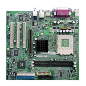
Page 11: The K7M-400A Mainboard
Overview The K7M-400A Mainboard 1 - 3... -
Page 12: Main Features
K7M-400A Mainboard Manual Main Features Duron: 1.0 - 1.3 GHz at FSB 200 MHz 1.6 - 1.8 GHz at FSB 266 MHz Athlon : 1.0 - 1.4 GHz at FSB 200/266 MHz Athlon XP: Palomino Core: 1500+ - 2100+ at FSB 266 MHz... - Page 13 Overview Audio Features AC97 2.2 compliant LINE_IN, LINE_OUT, MICROPHONE_IN Jack Front Audio Pinheaders I/O Ports 2 IDE Connectors - PIO, Bus Master, Ultra DMA 66/100/133 up to 4 Devices - 1 Serial Port COM1 / 1 CRT Port 2 Serial ATA Connectors 1 Floppy Connector 1 Parallel Port PS/2 Mouse and PS/2 Keyboard...
-
Page 14: Fic Unique Innovation For Users (Novus) - Enhanced Mainboard Features And System Support
K7M-400A Mainboard Manual FIC Unique Innovation for Users (NOVUS) - Enhanced Mainboard Features and System Support BIOS Guardian BIOS Guardian effectively acts as a fire-wall against viruses that can at- tack the BIOS while the system is running and when default is enabled. -
Page 15: Chapter 2 Installation Procedures
Installation Procedures Chapter 2 Installation Procedures The mainboard has several user-adjustable jumpers on the board that allow you to configure your system to suit your requirements. This chapter contains information on the various jumper settings on your mainboard. To set up your computer, you must complete the following steps: Step 1 - Set system jumpers Step 2 -... -
Page 16: Set System Jumpers
K7M-400A Mainboard Manual 1). Set System Jumpers Clear CMOS The CMOS RAM is powered by the onboard button cell battery. To clear the RTC data: (1) Turn off your computer; (2) Open the system case and disconnect the ATX power cable;... -
Page 17: Front Side Bus Frequency
Installation Procedures Front Side Bus Frequency The jumpers together decide the setting of FSB frequency of the mainboard. 2 - 3... -
Page 18: Install Memory Modules
K7M-400A Mainboard Manual 2). Install Memory Modules 1. Locate DDR DIMM sockets on the mainboard. 2. Install DDR DIMM straight down into the socket 1 using both hands, then socket 2, and so forth. 3. The clip on both ends of the... -
Page 19: Install The Cpu
Installation Procedures 3). Install the CPU The mainboard has a built-in Switching Voltage Regulator to support CPU Vcore autodetection. That is, it has the ability to detect and recognize the CPU voltage, clock, ratio. Users can view the report about CPU frequency through Frequency / Voltage Control on the BIOS Setup Screen. -
Page 20: Connect Atx Power
K7M-400A Mainboard Manual 3. Place the fan with heatsink on the CPU top and press down on the two plastic clips, hooking them up with the holes on the two sides of the retention module. 4. Press the white bar on each clip down to fasten the fan set on the retention module. -
Page 21: Install Expansion Cards
Installation Procedures The plug from the power supply can only be inserted in one orientation because of the different hole sizes. Find the proper orientation and push down firmly making sure that the pins are aligned. 4). Install Expansion Cards This section describes how to connect an expansion card to one of your system expansion slots. -
Page 22: Connect Devices
K7M-400A Mainboard Manual 2. Remove the corresponding slot cover from the computer chassis. Un- screw the mounting screw that secures the slot cover and pull the slot cover out from the computer chassis. Keep the slot cover mounting screw nearby. -
Page 23: Ide Device Connectors
Installation Procedures IDE Device Connectors The two connectors, IDE1 (PRIMARY) and IDE2 (SECONDARY), are used for your IDE hard disk drives, CD drives, LS-120|drives, or IDE ZIP drives. Insert the floppy ribbon cable (below) onto the floppy connector. The colored stripe (indicated by the arrow head, right) of the ribbon cable must be the same side as Pin 1. -
Page 24: Front Panel Block, Power Led, Ir And Speaker Connector
K7M-400A Mainboard Manual Front Panel Block, Power LED, IR, and Speaker Connector This block connector includes the connectors for linking with Power LED (3- pin), HDD LED, power button, power/sleep/message waiting button, and the reset button on the front panel of the system case. Please identify the polari- ties of the plug wires for the case speaker and LEDs. - Page 25 Installation Procedures (4) Power Button is connected with the power button. Pushing this switch allows the system to be turned on and off rather than using the power supply button. IR1/IR2 is a pinheader that is used for linking with your ID device to allow transmission of data to another system that also supports the IR feature.
-
Page 26: 1394 Connectors (Optional)
K7M-400A Mainboard Manual 1394 Connectors (optional) The 2 optional 1394 pinheaders on the board provides you, by an optional bracket with cable (see the figure below), with two connections for peripherals which have 1394 connectors. The pin definitions of the 1394 pinheaders are listed below also. -
Page 27: Spdif Out Connector
Installation Procedures CAUTION: Improper orientation of SPDIF connection may cause damage of your device. SPDIF Out Connector The mainboard equipped one 1x3 pinheader. It is used for SPDIF digi- tal audio output. Pin 1 is +5V, Pin 2 is SPDIF, Pin3 is GND. Serial IRQ Connector This 2-pin connector is used for some system integration use. -
Page 28: Chassis Intrusion Connector
K7M-400A Mainboard Manual Chassis Intrusion Connector This connector is for a chassis designed with intrusion detection feature. It needs a chassis intrusion sensoror on the chassis. If a chassis part is moved, the sensor activates and releases a signal in order to this connector to record a chassis intrusion event. -
Page 29: Serial Ata Connectors
Installation Procedures Serial ATA Connectors The 2 SATA connectors provide you with connections to serial ATA devices that conform to the Serial ATA specification. Serial ATA supports all ATA and ATAPI devices. The pictures below left show the two SATA cables (the top one is for power;... -
Page 30: Ps/2 Keyboard And Mouse Connector
K7M-400A Mainboard Manual PS/2 Keyboard and Mouse Connector These two 6-pin female (PS/2 keyboard is purple color and PS/2 mouse is green color) connectors are used for your PS/2 keyboard and PS/2 mouse. Printer Connector This 25-pin D-Sub female connector (burgundy-colored) is attached to your printer. -
Page 31: Universal Serial Bus Connectors
Installation Procedures Universal Serial Bus Connectors The mainbaord has six USB ports; four USB black jacks that are integrated on the edge of the board, the other two USB pinheaders on the board. They allows uses to attach to USB devices either from the rear or front panels. The USB cable that comes with your mainboard is used to connecting between the USB pinheaders and rear panel. -
Page 32: Serial Port Connector
K7M-400A Mainboard Manual Serial Port Connector COM1 (teal colored 9-pin D-sub male connector) allows you to connect with your device that use a serial port, such as a serial mouse or an external modem. Audio I/O Jacks LINE_OUT (lime) can be connected to headphones or preferably powered speakers. -
Page 33: Front Audio Connector
Installation Procedures Front Audio Connector The mainboard has a front panel audio F_AUDIO connector (Intel spec.). It allows users to attach the audio device via the front panel (instead of the rear panel) by a ribbon cable that in some cases. Its pin definitions are resented below. - Page 34 K7M-400A Mainboard Manual This Page Left Blank for Note 2 - 20...
-
Page 35: Chapter 3 Bios Setup
BIOS Setup Chapter 3 BIOS Setup The mainboard comes with a chip from Award BIOS that contains the ROM Setup information for your system. This chip serves as an interface between the processor and the rest of the mainboard components. This section ex- plains the information contained in the Setup program and tells you how to modify the settings according to your system configuration. -
Page 36: Standard Cmos Setup
K7M-400A Mainboard Manual Standard CMOS Setup The Standard CMOS Setup screen is displayed above. Each item may have one or more option settings. The system BIOS automatically detects memory size, thus no changes are necessary. Use the arrow keys to highlight the item and then use PgUp or PgDn keys to select the value you want in each item. - Page 37 BIOS Setup Hard Disks This field records the specifications for all non-SCSI hard drives installed in the system. The onboard PCI IDE connectors provide Primary and Sec- ondary channels for connecting up to four IDE hard disks or other IDE devices.
-
Page 38: Advanced Bios Features
K7M-400A Mainboard Manual Advanced BIOS Features Hard Disk Boot Priority This feature will auto detect all hard disks of bootable devices on the system. It also allows you to select hard disk device booting priority. CPU Internal Cache This controls the status of the processor’s internal cache area. - Page 39 BIOS Setup First/Second/Third Boot Device This feature allows you to select the boot device priority. The options are: Floppy, LS120, Hard Disk, CDROM, ZIP100, USB-FDD, USB-ZIP, USB-CDROM, LAN, Disabled. Boot Other Device This feature allows you to select the boot device priority. The options are: Enabled, Disabled.
- Page 40 K7M-400A Mainboard Manual Typematic Delay (Msec) This feature is available only if the item, Typematic Rate Setting, is set at Enabled. Sets the delay time before a character is repeated. The options are: 250, 500, 750, 1000 millisecond. Security Option Allows you to set the security level of the system.The options: Setup,...
-
Page 41: Advanced Chipset Features
BIOS Setup BIOS Guardian and Reflash BIOS BIOS Guardian by default is enabled, thus effectively acting as a fire- wall against viruses that can attack the BIOS while the system is running. It must be disabled before you reflash BIOS. The steps below show you how to turn the BIOS Guardian off and on when you want to reflash the BIOS: 1. - Page 42 K7M-400A Mainboard Manual DRAM Clock/Drive Control Current FSB Frequency, Current DRAM Frequency This item allows you to get current FSB and DRAM frequencies. DRAM Clock The feature allows users to select the DRAM clock. The options are: 133 MHz, 166 MHz, 200 MHz, By SPD.
- Page 43 BIOS Setup DRAM Command Rate This item allows users to set Address Time After command. The options are: 2T Command, l T Command. Write Recovery Time This item allows users to set write recovery time. The options are: 2T, 3T. tWTR This item allows users to set DRAM tWTR timing control.
- Page 44 K7M-400A Mainboard Manual AGP 3.0 Calibration cycle This feature allows users to enable or disable AGP 3.0cablibration cycle. The options are: Disabled, Enabled. VGA Share Memory Size It allows user to select the frame buffer size of VGA share memory.
-
Page 45: Integrated Peripherals
BIOS Setup Memory Hole When you install a Legacy ISA card, this feature allows you to select the memory hole address range of the ISA cycle when the processor accesses the selected address area. Please read your card manual for detail informa- tion. - Page 46 K7M-400A Mainboard Manual SATA Mode This item allows users to select the serial ATA mode The options are: IDE, Raid. IDE DMA transfer access This item allows users to disable the IDE DMA (Direct Memory Access) transfer access function. The options are: Enabled, Disabled.
- Page 47 BIOS Setup Secondary Master/Slave UDMA Allows an automatic configuration of the PCI secondary IDE hard drive (master/slave) mode if Ultra DMA is supported both on the motherboard and the hard disk. The options are: Auto, Disabled. IDE HDD Block Mode Block mode is also called block transfer, multiple commands, or multiple sector read/write.
- Page 48 K7M-400A Mainboard Manual USB Keyboard Support Your system contains a Universal Serial Bus (USB) controller and you have a USB keyboard Device. When set at Auto, the BIOS will detect if USB keyboard is installed automatically. The options are: Auto, Enabled, Disabled.
-
Page 49: Power Management Setup
BIOS Setup Init Display First When you install an AGP VGA card and a PCI VGA card on the board, this feature allows you to select which card the first initiation of the monitor display comes from. The options are: PCI Slot, AGP. Power Management Setup ACPI function This item allows you to disable the ACPI function. - Page 50 K7M-400A Mainboard Manual HDD Power Down This option lets the BIOS turn the HDD motor off when the systemis in Suspend mode. Selecting 1 Min,..,15 Min allows you to define the HDD idle time before the HDD enters the Power Saving Mode.
- Page 51 BIOS Setup Soft-Off by PWRBTN The selection Delay 4 Sec. will allow the system shut down after 4 seconds after the power button is pressed. The selection Instant-Off will allow the system shut down immediately once the power button is pressed. The settings are: Delay 4 Sec, Instant-Off.
-
Page 52: Pnp/Pci Configurations
K7M-400A Mainboard Manual Resume Time (hh:mm:ss) If an ATX power supply is installed and when RTC Alarm Resume is Enabled, this feature allows you to set the time of the alarm starts when the RTC Alarm Resume From Soft Off is set to be Enabled. - Page 53 BIOS Setup Reset Configuration Data Enabling this, resets the system Extended System Configuration Data (ESCD) when you exit Setup, if you have installed a new add-on card and the system reconfiguration has caused such a serious conflict that the operating system can not boot. The options are: Disabled, Enabled. Resources Controlled By If set at Auto, the BIOS arranges all system resources.
-
Page 54: Pc Health Status
K7M-400A Mainboard Manual PC Health Status Smart FAN Control This feature allows users to configure parameters of cooling fans. The rest of the items allow end users and technicians to monitor data provided by the BIOS on this mainboard. They are not user-configurable. -
Page 55: Save And Exit Setup
BIOS Setup Under the BIOS Feature Setup, if Setup is selected under the Security Option field and the Supervisor/User Password is enabled, you will be prompted for a password every time you try to enter the CMOS Setup Utility. If System is selected and the Supervisor/User Password is enabled, you will be requested to enter the Password every time you reboot the system or enter the CMOS Setup utility. - Page 56 K7M-400A Mainboard Manual This Page Left Blank for Notes 3 - 22...
-
Page 57: Bevor Sie Beginnen
Kurzanleitung Bevor Sie beginnen Diese Kurzanleitung zusammen mit dem EZ-Handbuch unterstützt Sie bei der Installation des Computersystems. Details entnehmen Sie bitte dem Handbuch. Statische Elektrizität kann integrierten Schaltungen auf dem Motherboard beschädigen. Bevor Sie ein Motherboard aus seiner Schützhülle herausnehmen, sollten Sie sicherstellen, dass sich keine statische Elektrizität auf Ihrem Körper befindet. - Page 58 Handbuch Installation der Hardware 1. Ziehen Sie den Hebel bis 90 Grad nach oben. 2. Installieren Sie die CPU und achten Sie dabei darauf, das der Stift 1 mit der Markierung auf der Sockelecke, die der Hebelspitze am nächsten liegt, ausgerichtet ist. Stecken Sie die CPU nicht gewaltsam hinein.
- Page 59 Kurzanleitung Arbeitsspeicher 1. Finden Sie die DDR-DIMM-Sockel auf dem Mainboard. 2. Stecken Sie das DDR-DIMM mit beiden Händen gerade nach unten in den Sockel 1 hinein, dann in Sockel 2, usw. 3. Die Klemme an beiden Enden des Sockels schließt sich, um das DDR-DIMM festzuhalten, wenn DDR-DIMM Sockelboden...
- Page 60 Handbuch Anschließen von Geräten 1. Finden Sie den Rahmen und die Aufnahme des Diskettenlaufwerks am Gehäuse. 2. Schieben Sie das Laufwerk von der Vorderseite in den Rahmen hinein. 3. Befestigen Sie das Laufwerk mit Schrauben am Rahmen. 4. Schließen Sie das Flachbandkabel und die Leitungsdrähte des Diskettenlaufwerks an.
- Page 61 Kurzanleitung 4. Schließen Sie das IDE-Flachbandkabel und die Leitungsdrähte an. Die farbige Linie auf dem Flachbandkabel (mit blauem Pfeilkopf) muss sich auf der gleichen Seite befinden, wie Stift 1 des Anschlusses. Anschließen einer Festplatte 1. Finden Sie den Rahmen und die Aufnahme der Festplatte am Gehäuse.
- Page 62 Handbuch Installieren von Karten 1. Wählen Sie einen verfügbaren Kartensteckplatz aus. 2. Entfernen Sie die Abdeckung des Steckplatzes vom Gehäuse. 3. Stecken Sie die Karte fest in den Steckplatz hinein. Befestigen Sie die Karte mit der Schraube. Anschließen des ATX-Netzteils Der Netzstecker mit 20 Löchern wird ATX-Netzanschluss verbunden.
- Page 63 Kurzanleitung Anschließen von Peripheriegeräten Schließen Sie Peripheriegeräte über die Rück-/Vorderseite an Ihr System an. System- PS/2-Maus Netzkabel Drucker PS/2-Tastatur USB-Flasch- Monitor Speichermodul Zur LAN-Buchse Joystick Lautsprecher BIOS-Setup...
- Page 64 Handbuch Standard CMOS Setup Markieren Sie den Menüpunkt mit den Pfeiltasten und wählen Sie den Wert für jeden Punkt mit den Tasten Bild-Nach-oben oder Bild-Nach- unten aus. Load Fail-Safe Defaults Dieses Untermenü dient zur Diagnose des Computers, wenn er nicht richtig startet.
-
Page 65: Avant De Commencer
Guide de référence rapide Avant de commencer Le présent guide de référence facile et le guide EZ ont pour but de vous aider à installer votre système informatique. Pour des informations plus détaillées, veuillez vous reporter au manuel de l'utilisateur. L'électricité... - Page 66 Manuel de la carte mère Installation de l'équipement Microprocesseur : 1. Faites pivoter le levier vers le haut de 90 degrés. 2. Installez le microprocesseur et vérifiez l'orientation de la broche 1 en alignant le coin marqué du socle avec le coin du socle le plus près de la pointe du levier.
- Page 67 Guide de référence rapide Mémoire 1. Repérez les emplacements DDR DIMM sur la carte mère. 2. Installez un module DDR DIMM directement dans le socle 1 en vous servant de vos deux mains, puis dans le socle 2, et ainsi de suite. 3.
- Page 68 Manuel de la carte mère Branchement de périphériques 1. Repérez le cadre pour lecteur de disquettes et pour disque dur sur le châssis. 2. Placez l'unité dans le cadre en l'insérant par le panneau avant. 3. Fixez l'unité sur le cadre avec des vis. 4.
- Page 69 Guide de référence rapide 4. Connectez le câble ruban IDE et les fils d'alimentation. La ligne colorée du câble (indiquée par une flèche bleue) doit être du même côté que la broche 1 du connecteur. Connexion du Disque dur 1. Repérez le cadre pour unité de disque dur sur le châssis. 2.
- Page 70 Manuel de la carte mère Installation des cartes 1. Sélectionnez un emplacement disponible pour carte. 2. Démontez le capot d'emplacement du châssis. 3. Poussez fermement la carte dans l'emplacement. Fixez la carte avec la vis. Connexion de l'unité d'alimentation ATX La prise d'alimentation 20 orifices sert à...
-
Page 71: Configuration Bios
Guide de référence rapide Branchement d'équipements périphériques Vous pouvez brancher des équipements périphériques sur le panneau arrière ou avant de votre système. Câble Souris alimentation PS/2 système Imprimante Clavier PS/2 Module mémoire Moniteur flash USB Sur prise LAN Manette de jeux Haut-parleurs Configuration BIOS... - Page 72 Manuel de la carte mère Configuration CMOS standard Utilisez les touches fléchées pour sélectionner l'élément voulu et utilisez les touches Pages préc. et Page suiv. pour sélectionner la valeur voulue pour chaque élément. Chargement des valeurs de sécurité (Fail-Safe) par défaut Ce menu secondaire est utilisé...
- Page 73 Referencia rápida Antes de comenzar Esta referencia rápida junto con la guía EZ se usan para ofrecerle asistencia al instalar el sistema en su ordenador. Para más información, lea el manual del usuario. La electricidad estática puede causar daños a los circuitos integrados de la placa base.
- Page 74 Manual de la Placa Base Instalación de hardware 1. Deslice la palanca hasta 90 grados. 2. Instale la CPU y asegúrese de que la orientación del pin 1 está alineada con la esquina más cercana a la punta de la palanca. No fuerce la inserción de la CPU.
- Page 75 Referencia rápida Memoria 1. Localice las ranuras DIMM DDR en la placa base. 2. Installe los DIMM DDR en las ranura 1 usando ambas manos, después en la ranura 2, y así continuamente. 3. Se cerrarán ambos extremos de la ranura para sostener el DIMM DDR en su lugar cuando el DIMM DDR llegue al fondo de la ranura.
- Page 76 Manual de la Placa Base Conexión de los dispositivos 1. Localice los huecos de la unidad de disco flexible y unidades de almacenamiento en la caja. 2. Coloque la unidad desde el lado del panel frontal en el hueco. 3. Fije la unidad en el hueco con los tornillos. 4.
- Page 77 Referencia rápida 4. Conecte el cable IDE de la unidad y los cables de alimentación. La linea de color en el cable (señalada con una flecha azul) debe estar en el mismo lado que el pin1 del conector. Conexión del Disco Duro 1.
- Page 78 Manual de la Placa Base Instalación de Tarjetas 1. Seleccione una ranura de tarjeta disponible. 2. Quite la cubierta de la ranura del chasis. 3. Presione la tarjeta firmemente en la ranura. Asegure la tarjeta con el tornillo. Conexión de la alimentación ATX El conector de 20 agujeros se conecta al conector de energía ATX.
- Page 79 Referencia rápida Conexión de Dispositivos Periféricos Conecte los dispositivos periféricos al sistema por madio del panel trasero/frontal. Cable de Ratón PS/2 alimentación del sistema Impresora Teclado PS/2 Módulo de Memoria Monitor Flash USB Al conector LAN Joystick Altavoz Configuración BIOS...
- Page 80 Manual de la Placa Base Configuración CMOS e stándar Use las teclas de cursor para resaltar el elemento y usar las teclas AvPág y RePág para seleccionar el valor que desee para cada elemento. Cargar opciones predeterminadas Puede seleccionar este submenú para diagnosticar el problema después de que inicie el ordenador, si el ordenador no ha iniciado correctamente.
- Page 81 快速參考指南 開始之前 本快速參考指南和 EZ 指南可以幫助您安裝電腦系統。有關的詳細資訊, 請閱讀用戶手冊。 靜電可能會損壞主板上的積體電路。從保護袋中 取出主板進行操作時,應確保身上沒有靜電。 在沒有正確牢固地安裝散熱片之前,切勿運行處 理器。否則,可能導致永久損壞! 包裝物品清單 如果下列任何物品損壞或缺失,請與經銷商聯繫。1. 主板 2. 軟碟驅動器 帶線 3. 80-針 IDE 帶線 4. USB 線 5. I/O 護蓋 6. SATA 線 (選購) 7.手冊 8. 驅 動程式 9. 1394 線 (選購)
- Page 82 主機板手册 安裝硬體 1. 將鎖杆向上擡起 90 度。 2. 安裝 CPU,將插座拐角標記對準距離鎖杆 頂端最近的插座拐角,確保管腳 1 的方向正 確。不要用力插入 CPU。 在 CPU 上面塗上一層熱物質;然後安裝經過 CPU 製造商認可的帶散熱片的風扇。向下按 鎖杆並鎖緊以固定 CPU。 3. 將帶散熱片的風扇放在 CPU 上面,然後 向下按兩個塑膠夾以鈎住支撐塊兩側的孔。 4. 向下按每個塑膠夾上的白色扳杆,將風扇 套件固定到支撐塊上。...
- Page 83 快速參考指南 記憶體 1. 在主板上找到 DDR DIMM 插槽。 2. 用雙手將第一條 DDR DIMM 垂直向下插入 插槽 1 中,第二條插入插槽 2 中,依次類 推。 3. 當 DDR DIMM 到達插槽底部後,插槽兩端 的卡子將鎖緊以使 DDR DIMM 安裝到位。 安裝主板 當使用電動螺絲刀時,將轉矩設置在允許的範圍 內:5.0 ~ 8.0kg/cm。 小心不要被設備的邊緣劃傷。 1. 在主板上找到安裝孔。 2. 將主板放在機箱內的托架上。務必對齊主 板和托架。 3. 用銅的栓棒固定主板。...
- Page 84 主機板手册 連接設備 1. 在機箱上找到軟碟驅動器托架和存放位置。 2. 從前面板一側將驅動器推入託架中。 3. 用螺絲將驅動器固定在托架上。 4. 連接軟帶線和電源線。帶線上的彩色線(帶藍色箭頭)必須 與插口的管腳 1 位於同一側。 連接 CD/DVD 驅動器 1. 在機箱上找到 CD/DVD 驅動器托架和存放位置。 2. 從前面板一側將驅動器推入託架中。 3. 用螺絲將驅動器固定在托架上。...
- Page 85 快速參考指南 4. 連接 IDE 帶線和電源線。帶線上的彩色線(帶藍色箭頭)必 須與插口的管腳 1 位於同一側。 連接硬碟驅動器 1. 在機箱上找到硬碟驅動器托架和存放位置。 2. 將硬碟驅動器從托架後部裝入,如箭頭所 示。 3. 用螺絲將驅動器固定在托架上。 4. 連接 IDE 帶線和電源線。帶線上的彩色線(帶藍色箭頭)必 須與插口的管腳 1 位於同一側。...
- Page 86 主機板手册 安裝卡 1. 選擇一個空閒的卡槽。 2. 從機箱上卸下槽蓋。 3. 將卡用力按入插槽中。用螺絲固定卡。 連接 ATX 電源 20-孔電源插頭連接到 ATX 電源插 口 上 。 4- 孔 電 源 插 頭 連 接 到 ATX_12V 電源插口上。 組裝系統機箱 裝上機箱蓋,然後用螺絲刀或手擰 緊蓋上的螺絲,如箭頭所示。...
- Page 87 快速參考指南 連接外設 通過前/後面板將外設連接到系統。 BIOS 設置...
- Page 88 主機板手册 標準 CMOS 設置 使用箭頭鍵高亮顯示專案,然後使用 PgUp 或 PgDn 鍵爲每個專 案選擇合適的值。 載入故障保護預設值 當電腦不能引導時,可以選擇此子功能表在電腦引導後診斷故 障。這些設置不會提供最佳的性能。 安裝驅動程式 驅動程式 將第一張實用程式光碟插入光碟驅動器中。頂級功能表將顯示在 螢幕上。選擇專案“驅動程式”將啓動自動運行功能。 幫助 此專案提供與功能和驅動程式有關的一些資訊。閱讀這些資訊將 對安裝有所幫助。 附帶軟體 此專案提供一些有用的軟體工具以幫助您管理電腦系統。...
- Page 89 快速参考指南 开始之前 本快速参考指南和 EZ 指南可以帮助您安装计算机系统。有关的详细信 息,请阅读用户手册。 静电可能会损坏主板上的集成电路。从保护袋中 取出主板进行操作时,应确保身上没有静电。 在没有正确牢固地安装散热片之前,切勿运行处 理器。否则,可能导致永久损坏! 包装物品清单 如果下列任何物品损坏或缺失,请与经销商联系。 1. 主板 2. 软盘驱动器带线 3. 40-针 IDE 带线 4. USB 线 5. I/O 护盖 6. SATA 线 (选件) 7. 手册 8. 驱动程序 9. 1394 线 (选件)
- Page 90 主板手册 安装硬件 1. 将锁杆向上抬起 90 度。 2. 安装 CPU,将插座拐角标记对准距离锁杆 顶端最近的插座拐角,确保管脚 1 的方向正 确。不要用力插入 CPU。 在 CPU 上面涂上一层热物质;然后安装经过 CPU 制造商认可的带散热片的风扇。向下按 锁杆并锁紧以固定 CPU。 3. 将带散热片的风扇放在 CPU 上面,然后 向下按两个塑料夹以钩住支撑块两侧的孔。 4. 向下按每个塑料夹上的白色扳杆,将风扇 套件固定到支撑块上。...
- Page 91 快速参考指南 内存 1. 在主板上找到 DDR DIMM 插槽。 2. 用双手将第一条 DDR DIMM 垂直向下插入 插槽 1 中,第二条插入插槽 2 中,依次类 推。 3. 当 DDR DIMM 到达插槽底部后,插槽两端 的卡子将锁紧以使 DDR DIMM 安装到位。 安装主板 当使用电动螺丝刀时,将转矩设置在允许的范围 内:5.0 ~ 8.0kg/cm。 小心不要被设备的边缘划伤。 1. 在主板上找到安装孔。 2. 将主板放在机箱内的托架上。务必对齐主 板和托架。 3. 用铜的栓棒固定主板。...
- Page 92 主板手册 连接设备 1. 在机箱上找到软盘驱动器托架和存放位置。 2. 从前面板一侧将驱动器推入托架中。 3. 用螺丝将驱动器固定在托架上。 4. 连接软带线和电源线。带线上的彩色线(带蓝色箭头)必须 与插口的管脚 1 位于同一侧。 连接 CD/DVD 驱动器 1. 在机箱上找到 CD/DVD 驱动器托架和存放位置。 2. 从前面板一侧将驱动器推入托架中。 3. 用螺丝将驱动器固定在托架上。...
- Page 93 快速参考指南 4. 连接 IDE 带线和电源线。带线上的彩色线(带蓝色箭头)必 须与插口的管脚 1 位于同一侧。 连接硬盘驱动器 1. 在机箱上找到硬盘驱动器托架和存放位置。 2. 将硬盘驱动器从托架后部装入,如箭头所 示。 3. 用螺丝将驱动器固定在托架上。 4. 连接 IDE 带线和电源线。带线上的彩色线(带蓝色箭头)必 须与插口的管脚 1 位于同一侧。...
- Page 94 主板手册 安装卡 1. 选择一个空闲的卡槽。 2. 从机箱上卸下槽盖。 3. 将卡用力按入插槽中。用螺丝固定卡。 连接 ATX 电源 20-孔电源插头连接到 ATX 电源插 口 上 。 4- 孔 电 源 插 头 连 接 到 ATX_12V 电源插口上。 组装系统机箱 装上机箱盖,然后用螺丝刀或手拧 紧盖上的螺丝,如箭头所示。...
- Page 95 快速参考指南 连接外设 通过前/后面板将外设连接到系统。 系统电源线 PS/2 鼠标 打印机 PS/2 键盘 USB 闪存模块 显示器 接 LAN 插口 操纵杆 音箱 BIOS 设置...
- Page 96 主板手册 标准 CMOS 设置 使用箭头键高亮显示项目,然后使用 PgUp 或 PgDn 键为每个项 目选择合适的值。 加载故障保护默认值 当计算机不能引导时,可以选择此子菜单在计算机引导后诊断故 障。这些设置不会提供最佳的性能。 安装驱动程序 驱动程序 将第一张实用程序光盘插入光盘驱动器中。顶级菜单将显示在屏 幕上。选择项目“驱动程序”将启动自动运行功能。 帮助 此项目提供与功能和驱动程序有关的一些信息。阅读这些信息将 对安装有所帮助。 附带软件 此项目提供一些有用的软件工具以帮助您管理计算机系统。...
Need help?
Do you have a question about the K7M-400A and is the answer not in the manual?
Questions and answers