Table of Contents
Advertisement
Quick Links
Advertisement
Table of Contents

Related Manuals for FIC PAK-2102


Summary of Contents for FIC PAK-2102
- Page 1 PAK-2102 PRELIMINARY MANUAL DOC No. : NA Rev. : NA Date : 1, 1997 Part No. : NA...
-
Page 2: Table Of Contents
Table of Contents Chapter 1 Overview Main Features ..................... 2 Chapter 2 Installation Procedures Mainboard Layout ..................6 1). Set System Jumpers ................7 Jumpers ..................... 7 Clear Password: CPW ............... 8 Flash EPROM Type Selection: EP1, EP2 ......... 8 2). - Page 3 PAK-2102 Mainboard Manual 5). Connect Cables and Power Supply ............31 Audio-In Connector: CD-IN ............. 31 Serial Port Connectors: COM1, COM2 ........31 CPU Fan Connectors: FAN ............32 Hardware MPEG Card Connector: FC, LPB ......32 Floppy Diskette Drive Connector: FLOPPY ......33 Front Panel Block Connector: F_PNL ........
-
Page 4: Chapter 1 Overview
72-pin SIMM sockets that accept an unrivaled choice of high-speed EDO and standard Fast Page Mode DRAM. The PAK-2102 integrates a full set of I/O features onboard, including two 16550 UART compatible serial ports, one EPP/ECP capable parallel port, and one Floppy Disk Drive controller. - Page 5 PAK-2102 Mainboard Manual Easy Installation Phoenix BIOS with support for Plug and Play, auto detection of Hard Drive and IDE features, and MS Windows 95™. Flexible Processor Support The onboard 321-pin ZIF socket supports Intel Pentium (P54C) CPU speed 75/90/100/120/133/150/166/200 MHz processors / P54CS / P54CTB / P55.P55C.
- Page 6 Overview Enhanced PCI Bus Master IDE Controller Integrated Enhanced PCI local bus IDE controller with two connectors supports up to four IDE devices such as Hard Disk, CD-ROM or Tape Backup drives via two channels for high speed data throughput. This controller supports PIO Modes 3 and 4, and DMA Mode 2 for optimized system performance.
- Page 7 PAK-2102 Mainboard Manual This Page Intentionally Left Blank...
-
Page 8: Installation Procedures
Chapter 2 Installation Procedures The PAK-2102 has several user-adjustable jumpers on the board that allow you to configure your system to suit your requirements. This chapter contains information on the various jumper settings on your mainboard. To set up your computer, you should follow these installation steps: ... -
Page 9: Mainboard Layout
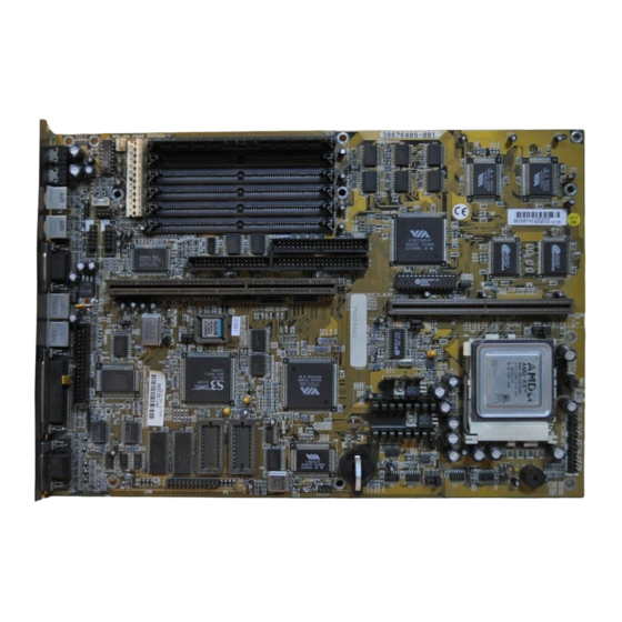
PAK-2102 Mainboard Manual Mainboard Layout... -
Page 10: Set System Jumpers
Installation Procedures 1). Set System Jumpers Jumpers Jumpers are used to select the operation modes for your system. Some jumpers on the board have three metal pins with each pin representing a different function. To set a jumper, a black cap containing metal contacts is placed over the jumper pins according to the required configuration. -
Page 11: Clear Password: Cpw
PAK-2102 Mainboard Manual Clear Password: CPW This jumper allows you to set the password configuration to Enabled or Disabled. You may need to enable this jumper if you forget your password. Flash EPROM Type Selection: EP1, EP2 This jumper allows you to configure the Flash EPROM chip. -
Page 12: Install Ram Modules
72-pin Single In-line Memory Modules (SIMMs). The PAK-2102 is able to support standard FPM (Fast Page Mode) and EDO (Extended Data Out) DRAM; and can accommodate onboard memory from 8 to 512MB using SIMMs. The mainboard has three memory banks: Bank 0, Bank 1, and Bank 2. -
Page 13: Ram Module Configuration
PAK-2102 Mainboard Manual RAM Module Configuration TOTAL SIMM 1 & 2 SIMM 3 & 4 SIMM 5 & 6 MEMORY (Bank 0) (Bank 1) (Bank 2) 4MB & 4MB 16MB 8MB & 8MB 4MB & 4MB 4MB & 4MB 24MB 4MB &... - Page 14 Installation Procedures TOTAL SIMM 1 & 2 SIMM 3 & 4 SIMM 5 & 6 MEMORY (Bank 0) (Bank 1) (Bank 2) 128MB 32MB & 32MB 32MB & 32MB 64MB & 64MB 32MB & 32MB 16MB & 16MB 16MB & 16MB 136MB 64MB &...
-
Page 15: Install Simms
PAK-2102 Mainboard Manual Install SIMMs Complete the following procedures to install SIMMs: CAUTION : Always turn the system power off before installing or removing any device. Always observe static electricity precautions. See “Handling Precautions” at the start of this manual. -
Page 16: Remove Simms
Installation Procedures 2. Carefully fit a SIMM at a 45 degree angle into each empty socket to be populated. All the SIMMs must face the same direction. 3. Swing each SIMM into its upright, locked position. When locking a SIMM in place, push on each end of the SIMM - do not push in the middle, as shown above. -
Page 17: Cache Memory
SRAMs. The PAK-2102 comes with onboard 256KB/512KB synchronous 3V Pipeline Burst SRAMs or a 256KB/512KB cache RAM module (FIC’s PC512K-3.0 is recommended) that can be installed on the cache RAM module slot. NOTE : Use the correct chips for the amount of cache memory you want to... -
Page 18: Onboard Cache Ram (256Kb/512Kb)
Installation Procedures Onboard Cache RAM (256KB/512KB) -
Page 19: Onboard Cache Ram And Ram Module Mixture (512Kb/1Mb)
PAK-2102 Mainboard Manual Onboard C ache RAM and RAM Module Mixture (512KB/1MB) -
Page 20: Ram Module
Installation Procedures RAM Module (256KB/512KB) -
Page 21: Install The Cpus
PAK-2102 Mainboard Manual 3). Install the CPU The CPU module resides in the Zero Insertion Force (ZIF) socket on the mainboard. - Page 22 Installation Procedures CAUTION : Always turn the system power off before installing or removing any device. Always observe static electricity precautions. See “Handling Precautions” at the start of this manual. Inserting the CPU chip incorrectly may damage the chip. To install the CPU, do the following: 1.
-
Page 23: Cpu External Clock (Bus) Frequency: Clk1, Clk2
PAK-2102 Mainboard Manual CPU External Clock (BUS) Frequency: CLK1, CLK2 The table below shows the jumper settings for the different CPU speed configurations. CPU to Bus Frequency Ratio: FREQ1, FREQ2 These two jumpers are used in combination to decide the ratio of the internal... -
Page 24: Intel Pentium Cpus
Installation Procedures Intel Pentium CPUs Frequency... -
Page 25: Voltage
PAK-2102 Mainboard Manual Voltage... -
Page 26: Amd-K5 Cpus
Installation Procedures AMD-K5 CPUs Frequency NOTE : * This CPU had not been tested when this manual was printed. ** For AMD CPUs only, jumper FREQ1/FREQ2 can be set for 1.75x bus ratratio. -
Page 27: Voltage
PAK-2102 Mainboard Manual Voltage... -
Page 28: Cyrix 6X86 Cpus
Installation Procedures Cyrix 6x86 CPUs Frequency NOTE : * This CPU had not been tested when this manual was printed. ** For Cyrix/IBM CPUs only, FREQ1/2 can be set for 3.5x bus ratio. -
Page 29: Voltage
PAK-2102 Mainboard Manual Voltage... -
Page 30: Ibm 6X86 Cpus
Installation Procedures IBM 6x86 CPUs Frequency NOTE : * This CPU had not been tested when this manual was printed. ** For Cyrix/IBM CPUs only, FREQ1/2 can be set for 3.5x bus ratio. -
Page 31: Voltage
PAK-2102 Mainboard Manual Voltage... -
Page 32: Installation Of Cyrix (Or Ibm) 6X86 Cpu Fan
Installation Procedures Installation of Cyrix (or IBM) 6x86 CPU Fan CAUTION : When you install a Cyrix (or IBM) 6x86 CPU fan, please pay attention to the direction of the air flow. Make sure that it lowers the temperature of the regulator. Otherwise, the system may overheat. We recommend that you use one of the following two CPU fans for the Cyrix (or IBM) 6x86 CPU when you install the fan on the mainboard. -
Page 33: Install Expansion Cards
PAK-2102 Mainboard Manual 4). Install Expansion Cards Add-on cards are printed circuit boards that, when connected to the mainboard, increase the capabilities of your system. For example, add-on cards can provide video and sound capabilities. CAUTION : Always turn the system power off before installing or removing any device. -
Page 34: Connect Cables And Power Supply
Installation Procedures 5). Connect Cables and Power Supply Audio-In Connector: CD-IN This 4-pin male connector is linked to the AUDIO-OUT port of your CD-ROM device via a ribbon cable. Serial Port Connectors: COM1, COM2 The COM1 is a 9-pin D-type male connector that allows you to connect with your devices that take serial ports, such as a serial mouse or a modem. -
Page 35: Cpu Fan Connectors: Fan
PAK-2102 Mainboard Manual CPU Fan Connector: FAN This connector is linked to the CPU fan. Hardware MPEG Card Connector: FC, LPB An optional MPEG card 1stGafx-CP3™ will be installed on an available PCI slot on the mainboard to improve the visual quality. -
Page 36: Floppy Diskette Drive Connector: Floppy
Installation Procedures Floppy Diskette Drive Connector: FLOPPY This 2x17 pin male connector connects to your floppy diskette drive (FDD) using the cable that is provided with this mainboard. -
Page 37: Front Panel Block Connector: F_Pnl
PAK-2102 Mainboard Manual Front Panel Block Connector: F_PNL This block connector includes: PW_LED, KB_LOCK, TB_LED, SP_SW, SPK, SP_LED, IDE_LED, RPW_SW, and RST connectors. Item Connector Pin Type Feature PW_LED 2-pin male indicates the system power status KB_LOCK 2-pin male allows the keyboard to access the... -
Page 38: Audio And Game Connector: Audio&Game
Installation Procedures Audio and Game Connector: AUDIO&GAME This connector is connected to the audio adapter card via a ribbon cable. The adapter card provides a 15-pin D-type female game port, a LINE_IN external jack and a LINE_OUT jack. The game port also functions as a MIDI port. -
Page 39: Infrared Connector: Ir
PAK-2102 Mainboard Manual Infrared Connector: IR This 2x5 pin male connector is used for connecting to the infrared (SIR) port and allows transmission of data to another system which also supports the SIR feature. Power Connector: POWER This 12 pin block connector is used for connecting to the standard 5V power supply. -
Page 40: Ide Hdd Device Connectors: Primary And Secondary
Installation Procedures IDE HDD Device Connector: PRIMARY and SECONDARY These two 2x20 pin male connectors are used for your IDE hard disks. If you have one IDE hard disk, connect it to the PRIMARY connector using the IDE HDD flat cable provided with the mainboard. The BIOS auto detection sets it to be a Primary Master disk. -
Page 41: Ps/2 Keyboard Connector: Ps2_Kb
PAK-2102 Mainboard Manual PS/2 Keyboard Connector: PS2_KB This 5 pin female connector is connected to the PS/2 keyboard. PS/2 Mouse Connector: PS2_MS This 5 pin female connector is connected to the PS/2 mouse. -
Page 42: Remote Power Connector: Rpw_Con
Installation Procedures Remote Power Supply Connector: RPW_CON This 3 pin male connector allows you to enable (or disable) the system power if the RPW_SW is on (or off). Universal Serial Bus Connectors (reserved for future upgrade) This connects to the port that allows you to attach a USB hub. The USB connectors are built-in for future upgrade of devices or peripherals that support Universal Serial Bus features. -
Page 43: Vga Connector: Vca
VGA DRAM size to 2MB, insert two 256Kx16Bits-7 (SOJ type) DRAM at locations M1, M2. The PAK-2102 supplies drivers for DOS and Windows-based programs; software drivers for other operating systems may be available in the future or upon request. These drivers will help you to utilize and to enhance the video subsystem of your computer system. -
Page 44: Display
Installation Procedures Display Your system has a standard memory of 2MB and provides an onboard VGA controller installed on your mainboard that supports various resolutions up to 1024 x 1280 in 16 colors under both the standard and enhanced VGA modes. It also supports 132-column text modes and non-interlaced monitors up to 72Hz refresh rates. -
Page 45: The Connector
PAK-2102 Mainboard Manual The Connector This 15 pin D-type female connector is connected to the VGA monitor. Wave Table Connector: WAVE The onboard audio system controller, CT2505, and FM synthesizser together with an optional wave table card CT1920 contributes an even better audio effect. - Page 46 Installation Procedures...
Need help?
Do you have a question about the PAK-2102 and is the answer not in the manual?
Questions and answers