
Related Manuals for FIC K8M-800T/M


Summary of Contents for FIC K8M-800T/M
- Page 1 K8M-800T/M MAINBOARD MANUAL DOC No.: M03601 Rev. : A0 Date : 9, 2003 Part No. : 25-11110-00...
- Page 2 Notice Handling Precautions Warning: 1. Static electricity may cause damage to the integrated circuits on the motherboard. Before handling any motherboard outside of its protective packaging, ensure that your body carries no static electric|charge. 2. There is a danger of explosion if the battery is incorrectly replaced.
-
Page 3: Table Of Contents
Chapter 1 Overview Package Checklist .................. 1-2 The K8M-800T/M Mainboard ............1-3 Main Features ..................1-4 FIC Unique Innovation for Users (NOVUS) - Enhanced Mainboard Features and System Support ....... 1-5 Chapter 2 Installation Procedures 1). Set System Jumpers ................. 2-2 Clear CMOS ................ - Page 4 K8M-800T/M Mainboard Manual CRT Connector (K8M-800M) ..........2-16 Audio I/O Jacks ............... 2-17 Front Audio Connector ............2-17 Printer Connector ..............2-18 Universal Serial Bus Connectors ........... 2-18 Chapter 3 BIOS Setup CMOS Setup Utility ................3-1 Standard CMOS Setup ................3-2 Advanced BIOS Features ..............
-
Page 5: Chapter 1 Overview
Overview Chapter 1 Overview This new Mainboard is a microATX sized board supporting the latest genera- tion of AMD™ processors at FSB 800MHz. Memory is up to DDR400 MHz and has 2 DDR SDRAM DIMMs fo r up to 2 GBs. This board provides users with an ATA133 data transaction for peripheral IDE drives . -
Page 6: Package Checklist
K8M-800T/M Mainboard Manual Package Checklist If you discover any item belo w was damaged or lost, please contact y our vendor. NOTE: A 1st Utilities CD that conta ins patch files, onboard video/ audio chip drivers, related online help and other useful information can be found in your mainboard package. -
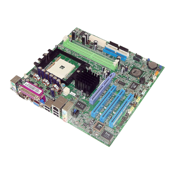
Page 7: The K8M-800T/M Mainboard
Overview The K8M-800T/M Mainboard 1 - 3... -
Page 8: Main Features
K8M-800T/M Mainboard Manual Main Features Athlon™ 64 processors from 3200+ and up* at FSB 800 MHz (*: not tested when this manual was printed) Chipset North Bridge: VIA K8T800 (K8M-800T) ® /K8M800(K8M-800M) South Bridge: VIA 8237 ® Memory 2 memory sockets :... -
Page 9: Fic Unique Innovation For Users (Novus)
IEEE 1394 Ports (optional) VT6307L™ 2 ports 1 bracket with cable FIC Unique Innovation for Users (NOVUS) - Enhanced Mainboard Features and System Support BIOS Guardian BIOS Guardian effectively acts as a fire-wall against viruses that can attack the BIOS while the system is running and when default is enabled. - Page 10 K8M-800T/M Mainboard Manual Easy Key Instead of completing the multi-layered BIOS setup process, these 3 Easy Key functions provid e direct access to Sub-Menu when completing BIOS settings adjustments. Easy-Keys are as follows: Ctrl + c: To enter clock settings menu.
-
Page 11: Chapter 2 Installation Procedures
Installation Procedures Chapter 2 Installation Procedures The mainboard has several user-adjustable jumpers on t he board that allow you to configure your system to suit your requirements. This chapter contains information on the various jumper settings on your mainboard. To set up your computer, you must complete the following steps: Step 1 - S et system jumpers Step 2 -... -
Page 12: Set System Jumpers
K8M-800T/M Mainboard Manual 1.) Set System Jumpers Clear CMOS The CMOS RAM is powered by the onboard button cell battery. To clear the RTC data: (1) Turn off your computer; (2) Open the system case and disconnect the ATX power cable;... -
Page 13: Install Memory Modules
Installation Procedures NOTE: Please refer to Front Panel Block Connector Section of this chapter for detail information. 2.) Install Memory Modules 1. Locate DDR DIMM sockets on the mainboard. 2. Install DDR DIMM straight down into socket 1, using both hands, then socket 2, and so forth. -
Page 14: Install The Cpu
K8M-800T/M Mainboard Manual 3. The clip on both ends of the socket will close to hold the DDR DIMM in place when the DDR DIMM reaches the bottom of the socket. Press the clips outward with both hands to remove the DIMM. -
Page 15: Connect Atx Power
Installation Procedures 3. Place the fan with h eatsink on the CPU top and pres s down on t he two plast ic clips, hooking t hem up wit h the holes o n the sides o f the retention module. 4. -
Page 16: Install Expansion Cards
K8M-800T/M Mainboard Manual NOTE: The CPU installing procedures should be: 1. Insert the CPU (with its fansink and retention module) on the socket. 2. Connect the 4-pin plug of the power supply 3. Connect the 20-pin plug of the power supply. - Page 17 Installation Procedures 1. Select an available expansion slot. 2. Remove th e correspo nding slot cover from the co mputer chassis. Un- screw the mounting screw that secures the slot cover and pull the slot cover out from the computer chassis. Keep the slot cover mounting screw nearby. 3.
-
Page 18: Connect Devices
K8M-800T/M Mainboard Manual 5). Connect Devices Floppy Diskette Drive Connector This connector provides the connection with your floppy disk drive. Insert the floppy ribbon cab le (below) onto th e floppy con nector. The colored stripe (indicated by the arrow, right) of th e ribbon cable must be on the same side as Pin 1. -
Page 19: Fan Connectors
Installation Procedures Fan Connectors The two connectors , CPU_FAN and SYS_FAN are linked t o the CPU fan and case fan, respectively. PWR_FAN can be used with the power supply cooling fan. Power Connectors The 20-pin male block connector is connected to the ATX power supply. The 4-pin male block connector is for the ATX_12V power supply. -
Page 20: Front Panel Block Connector
K8M-800T/M Mainboard Manual Front Panel Block Connector This block connector includes the co nn ect ors for linking with t he Power LED (3-p in), HDD LED, power but ton, p ower/s leep/mes- sage waiting button, and the reset bu tton on the fron t panel of t he sys tem case. -
Page 21: Ir And Speaker Connector
Installation Procedures (4) Power Button is connected with the power button. Pushing this switch allows the system to be turned on and off rather than using the power supply button. IR and Speaker Connector (1) IR is a pinheader that is used for linking with your ID device to allow transmission of data to another system that also supports the IR feature. -
Page 22: Serial Irq Connector
K8M-800T/M Mainboard Manual Serial IRQ Connector This 2-pin connecto r is used for some system integration use. Pin 1 is signal, Pin 2 is GND. Wake-On-LAN Connector This connector is used for connection with a network card with wake-on LAN feature. -
Page 23: Spdif Connectors
Installation Procedures SPDIF Connector The SPDIF_OUT conn ector is used for au dio out put wit h SPDIF spec. Pin definitions: Pin1 is 5V, Pin2 is SPDIF signal, Pin3 is GND. 1394 Connectors (optional) The 2 op tional 1394 pinheaders on th e board provid e you with two connec- tions for peripherals which have 1394 connectors through an optional bracket with cab le (see the fig ure below). -
Page 24: Cd Audio-In Connectors
K8M-800T/M Mainboard Manual CD Audio-In Connectors The connectors, CD_IN and AUX_IN, are for CD-ROM drive audio analog input use. Pin definitions: Pin1is Left, Pin2 and P3 is GND, Pin4 is GND. Types of Rear Panel I/O Connectors The rear panel I/O connectors of the K8M-800T and K8M-800M are different. -
Page 25: Ps/2 Keyboard And Mouse Connector
Installation Procedures PS/2 Keyboard and Mouse Connector These two 6-pin female connectors (keyboard is purple and mouse is green) are used for your PS/2 keyboard and PS/2 mouse. Serial Port Connectors (K8M-800T) COM1/2 (teal colored 9-pin D-sub male connectors) allow you to connect with your devices that use serial ports, such as a serial mouse or an external modem. -
Page 26: Serial Port Connectors (K8M-800M)
K8M-800T/M Mainboard Manual Serial Port Connectors (K8M-800M) COM1 (teal colored 9-pin D-su b male co nnecto r) and COM2 (9-pin male connector) allow you to connect with devices that use serial ports, such as a serial mouse or an external modem. -
Page 27: Audio I/O Jacks
Installation Procedures Audio I/O Jacks LINE_OUT (lime) can be conn ected to headp hones or p referably powered speakers. LINE_IN (light blue) allows tape players or oth er audio sources to be recorded by yo ur comp uter o r played thro ugh the LINE_OUT. MIC_IN (pink) allows microphones to be connected for audio input. -
Page 28: Printer Connector
K8M-800T/M Mainboard Manual Printer Connector This 25-pin D-Sub female connector (burgundy- colored) is attached to your printer. Universal Serial Bus Connectors The mainboard has eight USB ports; four USB black jacks that are integrated on the edge of the board, and four other USB ports (pinheaders) on the board. -
Page 29: Chapter 3 Bios Setup
BIOS Setup Chapter 3 BIOS Setup This mainboard comes with chip fro m Award BIOS that contains the ROM Setup information your system. (This chip serves as an interface between the p rocessor and the rest of the mainboard component s.) This section ex- plains the information cont ained in t he Setup p rogram and tells you how to modify the settings according to your system configuration. -
Page 30: Standard Cmos Setup
K8M-800T/M Mainboard Manual Standard CMOS Setup The Standard CMOS Setup screen is displayed above. Each feature may have one or more option settings. Use the arrow keys to highlight the feature you want to change and then use PgUp or PgDn to select the value you want fo r that feature. - Page 31 BIOS Setup Hard Disks This field records the specifications for all non-SCSI hard drives installed in the system. The onboard PCI IDE connectors provide Primary and Sec- ondary chan nels fo r conn ecting up to four IDE hard d isks o r other IDE devices.
-
Page 32: Advanced Bios Features
K8M-800T/M Mainboard Manual Advanced BIOS Features Hard Disk Boot Priority This feature will auto d etect all hard d isks of b ootable devices o n t he system. It also allows you to select hard disk device booting priority. - Page 33 BIOS Setup First/Second/Third Boot Device This feature allows you to select the boot device priority. The o ptions are: Flop py, LS120, Hard Disk, CDROM, ZIP100, USB-FDD, USB-ZIP, USB-CDROM, LAN, Disabled. Boot Other Device This feature allows you to select the boot device priority. The options are: Enabled, Disabled.
- Page 34 K8M-800T/M Mainboard Manual Security Option Allows yo u to s et the secu rity level o f the system.The option s: Set up, System. APIC Mode Allows you to decide if the system enters the APIC (Advanced Program- mable Interrupt Controller) mode or not for more IRQs can be released.
-
Page 35: Advanced Chipset Features
BIOS Setup BIOS Guardian and Reflash BIOS BIOS Guardian by default is enabled, thus effectively acting as a fire- wall ag ainst viru ses that can attack th e BIOS while t he sy stem is running. It must be disabled before you reflash BIOS. The steps below show you how t o the BIOS Guardian off and on when you want to reflash BIOS: 1. - Page 36 K8M-800T/M Mainboard Manual DDR Timing Setting by This feature allows you to decide DRAM clock timing. The options are: Auto, Manual. Max Memlock (Mhz) This feature allo ws yo u to place an artificial memory clock limit on the system. Memory is presented from running faster than this frequency.
- Page 37 BIOS Setup LDT & PCI Bus Control Upstream LDT Bus Width This feature allows you to select the range of upstreaming LDT (Lightning Data Transport) bus width. The options are: 8 bit, 16 bit. Downstream LDT Bus Width Th is feature allo ws yo u to select t he rang e of do wn st reaming LDT (Lightning Data Transport) bus width.
-
Page 38: Integrated Peripherals
K8M-800T/M Mainboard Manual Init Display First When you install an AGP VGA card and a PCI VGA card on the board, this feature allows you to select the first initiation of the monitor display from which card. The option s are: PCI Slot, AGP. - Page 39 BIOS Setup IDE DMA transfer access This item allo ws yo u to d isable the IDE DMA (Direct Memory Access) transfer access function. The options are: Enabled, Disabled. OnChip IDE Channel0/1 When enabled, this allows you to use the onboard primary/secondary PCI IDE.
- Page 40 K8M-800T/M Mainboard Manual IDE HDD Block Mode Block mode is also called block tran sfer, mu ltiple commands, or mult iple sector read/write. If your IDE hard drive supports block mode (most new drives do), select Enabled for automatic detection of the optimal number of block read/writes the drive can support per sector .
- Page 41 BIOS Setup UART Mode Select This allows you to select the IR modes if the serial port 2 is used as an IR port. Set at Normal, if you use COM2 as the serial port, instead of as an IR port.
-
Page 42: Power Management Setup
K8M-800T/M Mainboard Manual Power Management Setup ACPI function This feature allows you to disable the ACPI function. The options are: Enabled, Disabled. ACPI Suspend Type This featu re allows yo u to s elect suspen d mode when the sy stem is in ACPI mode. - Page 43 BIOS Setup Suspend Mode When disabled, the system will not enter Suspend mode. The specified time option defines the idle time the system takes before it enters Suspend mode. The options are: Disable, 1, 2, 4, 8, 10, 20, 30, 40 Min, 1 Hour. Video Off Option This feature provides the select ions o f the v ideo display p ower saving mode.
- Page 44 K8M-800T/M Mainboard Manual AC Loss Auto Restart When the system is shut down due to a power failure, the system will not power back on by itself. This feature allows you to set the system back to which power status when the system power is resumed. It will always be back to on if set at On.
- Page 45 BIOS Setup RTC Alarm Resume Enabled allows you to set the time the system will be tu rned on from the system power-off status. The options are: Enabled, Disabled. Date (of Month) This feature allows yo u to set the day o f the alarm start s when th e RTC Alarm Resume From Soft Off is set to be Enabled.
-
Page 46: Pnp/Pci Configurations
K8M-800T/M Mainboard Manual PnP/PCI Configurations PNP OS Installed If your operating system supports Plug-and-Play, such as Windows NT or Windows 95, select Yes. The options are: No, Yes. Reset Configuration Data Enablin g this, resets the syst em Exten ded Syst em Co nfig uration Data... -
Page 47: Pc Health Status
BIOS Setup Assign IRQ For VGA If your PCI VGA card devices do not need an IRQ, select Disabled; there- fore, an IRQ can be released for the system use. The options are: Enabled, Disabled. Assign IRQ For USB If your USB devices do not need an IRQ, select Disabled; therefore, an IRQ can be released for the system use. -
Page 48: Frequency/Voltage Control
K8M-800T/M Mainboard Manual Frequency/Voltage Control Auto Detect PCI Clk When enabled, BIOS will detect the PCI slot slot. If no devices are installed, the BIOS will auto disable its clock. The options are: Enabled, Disabled. Spread Spectrum This feature allows you to disable the spread spectrum. -
Page 49: Save And Exit Setup
BIOS Setup Under the BIOS Feature Setup, if Setup is selected under the Security Option field and the Supervisor/User Password is enabled, you will be prompted for the password every time you try to enter the CMOS Setup Utility. If System is selected and the Supervisor/User Password is enabled, you will be requested to enter the Password every time you reboot the sy stem or enter the CMOS Setup utility. - Page 50 K8M-800T/M Mainboard Manual 3 - 22...
- Page 51 Quick Reference Before Start This quick reference together with the EZ guide is used for providing you with the assistance when installing computer system. For detail information, please read the user manual. Static electricity may cause damage to the integrated circuits on the motherboard.
-
Page 52: Hardware Installation
K8M-800T/M Mainboard Manual Hardware Installation 1. Swing the lever upword to 90 degree. 2. Install the CPU and make sure the the pin 1 orientation by aligning the socket corner marking with the socket corner closest to the lever tip. Do not insert the CPU by force. - Page 53 Quick Reference Memory 1. Locate DDR DIMM sockets on the mainboard. 2. Install DDR DIMM straight down into the socket 1 using both hands, then socket 2, and so forth. 3. The clip on both ends of the socket will close up to hold the DDR DIMM in place when the DDR DIMM reaches the socket bottom.
- Page 54 K8M-800T/M Mainboard Manual Connecting Devices 1. Locate floppy drive frame and storage on the chassis. 2. Place the drive from the front panel side into the frame. 3. Affix the drive on the frame by screws. 3. Connect the floppy ribbon cable and power wires. The colored line on the ribbon cable (pointed by blue arrowhead) must be the same side with the pin1 of the connector.
- Page 55 Quick Reference 4. Connect the IDE ribbon cable and power wires. The colored line on the cable (pointed by blue arrowhead) must be the same side with the pin1 of the connector. Connecting Hard Drive 1. Locate hard drive frame and storage on the chassis. 2.
- Page 56 K8M-800T/M Mainboard Manual Installing Cards 1. Select an available card slot. 2. Remove the slot cover from chassis. 3. Push the card firmly into the slot. Secure the card with the screw. Connecting ATX Power The 20-hole power plug is connected to ATX power connector.
-
Page 57: Bios Setup
Quick Reference Attach Peripheral Devices Link peripheral devices to your system via rear/front panel. BIOS Setup... -
Page 58: Driver Installation
K8M-800T/M Mainboard Manual Standard CMOS Setup Use the arrow keys to highlight the item and then use PgUp or PgDn keys to select the value you want in each item. Load Fail-Safe Defaults This submenu is selected to diagnose the problem after the computer boots, if the computer will not boot. -
Page 59: Avant De Commencer
Guide de référence rapide Avant de commencer Le présent guide de référence facile et le guide EZ ont pour but de vous aider à installer votre système informatique. Pour des informations plus détaillées, veuillez vous reporter au manuel de l'utilisateur. L'électricité... - Page 60 Manuel de la carte mère K8M-800T/M Installation de l'équipement Microprocesseur : 1. Faites pivoter le levier vers le haut de 90 degrés. 2. Installez le microprocesseur et vérifiez l'orientation de la broche 1 en alignant le coin marqué du socle avec le coin du socle le plus près de la pointe du levier.
- Page 61 Guide de référence rapide Mémoire 1. Repérez les emplacements DDR DIMM sur la carte mère. 2. Installez un module DDR DIMM directement dans le socle 1 en vous servant de vos deux mains, puis dans le socle 2, et ainsi de suite. 3.
- Page 62 Manuel de la carte mère K8M-800T/M Branchement de périphériques 1. Repérez le cadre pour lecteur de disquettes et pour disque dur sur le châssis. 2. Placez l'unité dans le cadre en l'insérant par le panneau avant. 3. Fixez l'unité sur le cadre avec des vis.
- Page 63 Guide de référence rapide 4. Connectez le câble ruban IDE et les fils d'alimentation. La ligne colorée du câble (indiquée par une flèche bleue) doit être du même côté que la broche 1 du connecteur. Connexion du Disque dur 1. Repérez le cadre pour unité de disque dur sur le châssis. 2.
- Page 64 Manuel de la carte mère K8M-800T/M Installation des cartes 1. Sélectionnez un emplacement disponible pour carte. 2. Démontez le capot d'emplacement du châssis. 3. Poussez fermement la carte dans l'emplacement. Fixez la carte avec la vis. Connexion de l'unité d'alimentation ATX La prise d'alimentation 20 orifices sert à...
-
Page 65: Configuration Bios
Guide de référence rapide Branchement d'équipements périphériques Vous pouvez brancher des équipements périphériques sur le panneau arrière ou avant de votre système. Câble Souris alimentation PS/2 système Imprimante Clavier PS/2 Module mémoire Moniteur flash USB Sur prise LAN Manette de jeux Haut-parleurs Configuration BIOS... - Page 66 Manuel de la carte mère K8M-800T/M Configuration CMOS standard Utilisez les touches fléchées pour sélectionner l'élément voulu et utilisez les touches Pages préc. et Page suiv. pour sélectionner la valeur voulue pour chaque élément. Chargement des valeurs de sécurité (Fail-Safe) par défaut Ce menu secondaire est utilisé...
-
Page 67: Bevor Sie Beginnen
Kurzanleitung Bevor Sie beginnen Diese Kurzanleitung zusammen mit dem EZ-Handbuch unterstützt Sie bei der Installation des Computersystems. Details entnehmen Sie bitte dem Handbuch. Statische Elektrizität kann integrierten Schaltungen auf dem Motherboard beschädigen. Bevor Sie ein Motherboard aus seiner Schützhülle herausnehmen, sollten Sie sicherstellen, dass sich keine statische Elektrizität auf Ihrem Körper befindet. - Page 68 Handbuch Installation der Hardware 1. Ziehen Sie den Hebel bis 90 Grad nach oben. 2. Installieren Sie die CPU und achten Sie dabei darauf, das der Stift 1 mit der Markierung auf der Sockelecke, die der Hebelspitze am nächsten liegt, ausgerichtet ist. Stecken Sie die CPU nicht gewaltsam hinein.
- Page 69 Kurzanleitung Arbeitsspeicher 1. Finden Sie die DDR-DIMM-Sockel auf dem Mainboard. 2. Stecken Sie das DDR-DIMM mit beiden Händen gerade nach unten in den Sockel 1 hinein, dann in Sockel 2, usw. 3. Die Klemme an beiden Enden des Sockels schließt sich, um das DDR-DIMM festzuhalten, wenn DDR-DIMM Sockelboden...
- Page 70 Handbuch Anschließen von Geräten 1. Finden Sie den Rahmen und die Aufnahme des Diskettenlaufwerks am Gehäuse. 2. Schieben Sie das Laufwerk von der Vorderseite in den Rahmen hinein. 3. Befestigen Sie das Laufwerk mit Schrauben am Rahmen. 4. Schließen Sie das Flachbandkabel und die Leitungsdrähte des Diskettenlaufwerks an.
- Page 71 Kurzanleitung 4. Schließen Sie das IDE-Flachbandkabel und die Leitungsdrähte an. Die farbige Linie auf dem Flachbandkabel (mit blauem Pfeilkopf) muss sich auf der gleichen Seite befinden, wie Stift 1 des Anschlusses. Anschließen einer Festplatte 1. Finden Sie den Rahmen und die Aufnahme der Festplatte am Gehäuse.
- Page 72 Handbuch Installieren von Karten 1. Wählen Sie einen verfügbaren Kartensteckplatz aus. 2. Entfernen Sie die Abdeckung des Steckplatzes vom Gehäuse. 3. Stecken Sie die Karte fest in den Steckplatz hinein. Befestigen Sie die Karte mit der Schraube. Anschließen des ATX-Netzteils Der Netzstecker mit 20 Löchern wird ATX-Netzanschluss verbunden.
- Page 73 Kurzanleitung Anschließen von Peripheriegeräten Schließen Sie Peripheriegeräte über die Rück-/Vorderseite an Ihr System an. System- PS/2-Maus Netzkabel Drucker PS/2-Tastatur USB-Flasch- Monitor Speichermodul Zur LAN-Buchse Joystick Lautsprecher BIOS-Setup...
- Page 74 Handbuch Standard CMOS Setup Markieren Sie den Menüpunkt mit den Pfeiltasten und wählen Sie den Wert für jeden Punkt mit den Tasten Bild-Nach-oben oder Bild-Nach- unten aus. Load Fail-Safe Defaults Dieses Untermenü dient zur Diagnose des Computers, wenn er nicht richtig startet.
- Page 75 Consultazione rapida Prima di iniziare Questa Guida di consultazione rapida insieme alla Guida facile è utilizzata per fornire assistenza durante l’installazione del sistema PC. Per informazioni dettagliate si prega di fare riferimento al Manuale utente. L’elettricità statica può provocare danni ai circuiti integrati della scheda madre.
- Page 76 Manuale scheda madre K8M-800T/M Installazione dell’hardware 1. Spostare la levetta in lato di 90 gradi. 2. Installare la CPU e controllare l’orientamento del pin 1 allineando il contrassegno sull’angolo della presa con il contrassegno più vicino alla punta della levetta. Non forzare la CPU.
- Page 77 Riferimento rapido Memoria 1. Ubicare gli alloggiamenti DIMM DDR sulla scheda madre. 2. Installare i moduli DIMM DDR spingendoli con entrambe le mani verso il basso nella presa 1, poi la 2, e così avanti. 3. I fermagli su entrambi i lati della presa fisseranno e bloccheranno i moduli DIMM DDR quando raggiungono il fondo dell’alloggiamento.
- Page 78 Manuale scheda madre K8M-800T/M Collegamento dei dispositivi 1. Ubicare la cornice e l’alloggiamento dell’unità dischetti sul telaio. 2. Inserire l’unità dalla parte frontale del telaio. 3. Fissare l’unità alla cornice con le viti. 4. Collegare il cavo a nastro ed i cavi d’alimentazione La riga colorata sul cavo anastro (freccia blu) deve trovarsi nella stessa direzione con il pin1 del connettore.
- Page 79 Riferimento rapido 4. Collegare il cavo IDE ed i cavi d’alimentazione La riga colorata sul cavo (freccia blu) deve trovarsi nella stessa direzione con il pin1 del connettore. Collegamento del disco rigido 1. Ubicare la cornice e l’alloggiamento dell’unità disco rigido sul telaio.
- Page 80 Manuale scheda madre K8M-800T/M Installazione delle schede 1. Selezionare un alloggiamento scheda disponibile. Rimuovere copertura dell’alloggiamento dal telaio. 3. Spingere con fermezza la scheda nell’alloggiamento. Fissare la scheda con le viti. Collegamento alimentazione ATX La presa di corrente a 20 fori è...
- Page 81 Riferimento rapido Collegamento delle periferiche Collegare le periferiche al sistema tramite il pannello frontale / posteriore. Cavo Mouse alimentazione PS/2 sistema Stampante Tastiera PS/2 Modulo memoria Monitor Flash USB Al connettore LAN Joystick Casse Impostazione BIOS...
- Page 82 Manuale scheda madre K8M-800T/M Standard CMOS Setup Utilizzare le frecce per evidenziare la voce ed utilizzare i tasti PgUp o PgDn per selezionare il valore desiderato per ciascuna voce. Load Fail-Safe Defaults Questo menu secondario è selezionato per diagnosticare il problema dopo il riavvio del computer, se il computer non si avvia.
- Page 83 Referencia rápida Antes de comenzar Esta referencia rápida junto con la guía EZ se usan para ofrecerle asistencia al instalar el sistema en su ordenador. Para más información, lea el manual del usuario. La electricidad estática puede causar daños a los circuitos integrados de la placa base.
- Page 84 Manual de la Placa Base Dynasty K8M-800T/M Instalación de hardware 1. Deslice la palanca hasta 90 grados. 2. Instale la CPU y asegúrese de que la orientación del pin 1 está alineada con la esquina más cercana a la punta de la palanca. No fuerce la inserción de la CPU.
- Page 85 Referencia rápida Memoria 1. Localice las ranuras DIMM DDR en la placa base. 2. Installe los DIMM DDR en las ranura 1 usando ambas manos, después en la ranura 2, y así continuamente. 3. Se cerrarán ambos extremos de la ranura para sostener el DIMM DDR en su lugar cuando el DIMM DDR llegue al fondo de la ranura.
- Page 86 Manual de la Placa Base Dynasty K8M-800T/M Conexión de los dispositivos 1. Localice los huecos de la unidad de disco flexible y unidades de almacenamiento en la caja. 2. Coloque la unidad desde el lado del panel frontal en el hueco.
- Page 87 Referencia rápida 4. Conecte el cable IDE de la unidad y los cables de alimentación. La linea de color en el cable (señalada con una flecha azul) debe estar en el mismo lado que el pin1 del conector. Conexión del Disco Duro 1.
- Page 88 Manual de la Placa Base Dynasty K8M-800T/M Instalación de Tarjetas 1. Seleccione una ranura de tarjeta disponible. 2. Quite la cubierta de la ranura del chasis. 3. Presione la tarjeta firmemente en la ranura. Asegure la tarjeta con el tornillo.
- Page 89 Referencia rápida Conexión de Dispositivos Periféricos Conecte los dispositivos periféricos al sistema por madio del panel trasero/frontal. Cable de Ratón PS/2 alimentación del sistema Impresora Teclado PS/2 Módulo de Memoria Monitor Flash USB Al conector LAN Joystick Altavoz Configuración BIOS...
- Page 90 Manual de la Placa Base Dynasty K8M-800T/M Configuración CMOS e stándar Use las teclas de cursor para resaltar el elemento y usar las teclas AvPág y RePág para seleccionar el valor que desee para cada elemento. Cargar opciones predeterminadas Puede seleccionar este submenú para diagnosticar el problema después de que inicie el ordenador, si el ordenador no ha iniciado correctamente.
- Page 91 クイックリファレンス 始める前に このクイックリファレンスをEZガイドと共に使用すると、コンピュータシステ ムを簡単にインストールすることができます。詳細は、ユーザーマニュアルをお 読みください。 静電気は、マザーボードの統合回路を損傷する原因と なります。保護包装の外側でマザーボードを扱う前 に、身体に静電気が帯電していないことを確認してく ださい。 ヒートシンクを適切にしっかり取り付けていない状態 では、プロセッサを決して作動しないでください。永 久的な損傷の原因となります! 梱包のチェックリスト 付属品が足りないときは破損しているときは、ベンダーに連絡してください。 メインボード フロッピードライブケ USB ケーブル 80 ピン IDE リボンケー ーブル (オプション) ブル I/O シールド マニュアル ドライバ ケーブル付き SATA ケーブル付き 1394 ブラ (オプション) ケット(オプション)...
- Page 92 K8M -800T/M メインボードマニュアル ハードウェアの取り付け 1. レバーを90度上に回します。 2. CPUを取付け、ソケットの隅のマーキング をレバーチップのすぐ傍のソケットの隅に 合わせて、ピン1の方向を確認します。無理 にCPUを差し込まないでください。 CPUの上に感熱糊を塗り、CPUメーカーが承 認したヒートシンクの付いたファンを取り 付けます。レバーを下方向に押してCPUを固 定したら、ロックします。 3. ヒートシンクの付いたファンをCPUの上 に配置し、2本のプラスチックのチップを押 し下げて、両側のリテンションモジュール に取り付けます。 4. 白いバーを各クリップに押し下げて、リ テンションモジュールにファンセットを固 定します。...
- Page 93 クイックリファレンス メモリ 1. マザーボードで、DDR DIMMソケットを探します。 2. 両手を使用してDDR DIMMをソケット1、 ソケット2といった具合に、真下に押して取 り付けます。 3. ソケットの両端のクリップを閉じると、 DDR DIMMがソケット下部に達したときに、 DDR DIMMは適切な場所に固定されます。 メインボードのマウント 電動ネジ回しを使用するとき、トルクは5.0 ~ 8.0kg/cmの許容範囲に設定されます。 デバイスの端に注意してください。 1. メインボードでマウンティングホールを 探します。 2. ボードをシャーシ内部のフレームの上に 取り付けます。ボードとフレームの位置が あっていることを確認してください。 3. 銅の支柱メインボードでメインボードを 固定します。...
- Page 94 K8M -800T/M メインボードマニュアル デバイスの接続 1. シャーシでフロッピードライブのフレームと記 憶装置を探します。 2. フロントパネルのサイドのドライブをフ レームに取り付けます。 3. ネジでフレームにドライブを取り付けま す。 4. フロッピーリボンケーブルと電源ワイヤを接続します。リボ ンケーブルの色の付いた線(青い矢印でポイント)は、コネク タのピン1と同じ側にある必要があります。 ドライブの接続 CD/DVD 1. シャーシでCD/DVDドライブのフレームと記憶装置を探します。 2. フロントパネルのサイドのドライブをフ レームに取り付けます。 3. ネジでフレームにドライブを取り付けま す。...
- Page 95 クイックリファレンス 4. IDEリボンケーブルと電源ワイヤを接続します。ケーブルの 色の付いた線(青い矢印でポイント)は、コネクタのピン1と 同じ側にある必要があります。 ハードドライブの接続 1. シャーシでハードドライブのフレームと記憶装置を探します。 2. 矢印が示すように、フレームの背面のハ ードディスクドライブを取り付けます。 3. ネジでフレームにドライブを取り付けます。 4. IDEリボンケーブルと電源ワイヤを接続します。ケーブルの 色の付いた線(青い矢印でポイント)は、コネクタのピン1と 同じ側にある必要があります。...
- Page 96 K8M -800T/M メインボードマニュアル カードの取り付け 1. 開いているカードスロットを選択します。 2. シャーシからスロットカバーを 取り外します。 3. カードをスロットにしっかりと押します。ネジでカードを 固定します。 電源の接続 20穴の電源プラグを、ATX電源 コネクタに接続します。4穴の 電源プラグをATX_12V電源コ ネクタに接続します。 アセンブリシステムケース シャーシのカバーを取り付け、ね じ回しか指でカバーのネジを(矢 印がポイントするように)回して 締め付けます。...
- Page 97 クイックリファレンス 周辺装置の取り付け 背面/前面パネルによって、システムに周辺装置を結合します。 PS/2 マウス シ ステム電源ケ ーブ プリンタ PS/2 キーボード USB フラッシュメモ モニタ リモジュール LAN ジャックへ ジョイスティッ ク スピーカー BIOS のセットアップ...
- Page 98 K8M -800T/M メインボードマニュアル 標準CMOSのセットアップ 矢印キーを使用してアイテムを強調表示し、PgUp または PgDn キーを使って、各アイテムに希望する値を選択します。 フェールセーフデフォルトのロード このサブメニューは、コンピュータが起動しても、コンピュー タが起動しない場合の問題を診断するために選択します。これ らの設定は、最適のパフォーマンスを提供しません。 ドライバのインストール ドライバ CDドライブに最初のユーティリティCDを挿入します。画面に トップメニューが表示されます。アイテムのドライバを選択し、 自動実行機能を開始します。 ヘルプ このアイテムは、機能とドライバに関する一部の情報を提供し ます。この情報を読めば、インストールを簡単に行うことがで きます。 ソフトウェアバンドル このアイテムは役に立つソフトウェアツールを提供して、コン ピュータシステムの管理を容易にします。...
- Page 99 快速參考指南 開始之前 本快速參考指南和 EZ 指南可以幫助您安裝電腦系統。有關的詳細資訊, 請閱讀用戶手冊。 靜電可能會損壞主板上的積體電路。從保護袋中 取出主板進行操作時,應確保身上沒有靜電。 在沒有正確牢固地安裝散熱片之前,切勿運行處 理器。否則,可能導致永久損壞! 包裝物品清單 如果下列任何物品損壞或缺失,請與經銷商聯繫。 主板 軟碟驅動器帶 80-針 IDE 帶 USB 線 線 線 (選件) I/O 護蓋 手册 驅動程式 1394 線板和帶線 SATA 電源線(上) (選件) SATA 資料線(下) (選件)...
- Page 100 K8M-800T/M 主機板手册 安裝硬體 1. 將鎖杆向上擡起 90 度。 2. 安裝 CPU,將插座拐角標記對準距離鎖杆 頂端最近的插座拐角,確保管腳 1 的方向正 確。不要用力插入 CPU。 在 CPU 上面塗上一層熱物質;然後安裝經過 CPU 製造商認可的帶散熱片的風扇。向下按 鎖杆並鎖緊以固定 CPU。 3. 將帶散熱片的風扇放在 CPU 上面,然後 向下按兩個塑膠夾以鈎住支撐塊兩側的孔。 4. 向下按每個塑膠夾上的白色扳杆,將風扇 套件固定到支撐塊上。...
- Page 101 快速參考指南 記憶體 1. 在主板上找到 DDR DIMM 插槽。 2. 用雙手將第一條 DDR DIMM 垂直向下插入 插槽 1 中,第二條插入插槽 2 中,依次類 推。 3. 當 DDR DIMM 到達插槽底部後,插槽兩端 的卡子將鎖緊以使 DDR DIMM 安裝到位。 安裝主板 當使用電動螺絲刀時,將轉矩設置在允許的範圍 內:5.0 ~ 8.0kg/cm。 小心不要被設備的邊緣劃傷。 1. 在主板上找到安裝孔。 2. 將主板放在機箱內的托架上。務必對齊主 板和托架。 3. 用銅的栓棒固定主板。...
- Page 102 K8M-800T/M 主機板手册 連接設備 1. 在機箱上找到軟碟驅動器托架和存放位置。 2. 從前面板一側將驅動器推入託架中。 3. 用螺絲將驅動器固定在托架上。 4. 連接軟帶線和電源線。帶線上的彩色線(帶藍色箭頭)必須 與插口的管腳 1 位於同一側。 連接 CD/DVD 驅動器 1. 在機箱上找到 CD/DVD 驅動器托架和存放位置。 2. 從前面板一側將驅動器推入託架中。 3. 用螺絲將驅動器固定在托架上。...
- Page 103 快速參考指南 4. 連接 IDE 帶線和電源線。帶線上的彩色線(帶藍色箭頭)必 須與插口的管腳 1 位於同一側。 連接硬碟驅動器 1. 在機箱上找到硬碟驅動器托架和存放位置。 2. 將硬碟驅動器從托架後部裝入,如箭頭所 示。 3. 用螺絲將驅動器固定在托架上。 4. 連接 IDE 帶線和電源線。帶線上的彩色線(帶藍色箭頭)必 須與插口的管腳 1 位於同一側。...
- Page 104 K8M-800T/M 主機板手册 安裝卡 1. 選擇一個空閒的卡槽。 2. 從機箱上卸下槽蓋。 3. 將卡用力按入插槽中。用螺絲固定卡。 連接 ATX 電源 20-孔電源插頭連接到 ATX 電源插 口 上 。 4- 孔 電 源 插 頭 連 接 到 ATX_12V 電源插口上。 組裝系統機箱 裝上機箱蓋,然後用螺絲刀或手擰 緊蓋上的螺絲,如箭頭所示。...
- Page 105 快速參考指南 連接外設 通過前/後面板將外設連接到系統。 BIOS 設置...
- Page 106 K8M-800T/M 主機板手册 標準 CMOS 設置 使用箭頭鍵高亮顯示專案,然後使用 PgUp 或 PgDn 鍵爲每個專 案選擇合適的值。 載入最佳預設值 可以選擇此子功能表。這些設置提供最佳的性能。 安裝驅動程式 驅動程式 將第一張實用程式光碟插入光碟驅動器中。頂級功能表將顯示在 螢幕上。選擇專案“驅動程式”將啓動自動運行功能。 幫助 此專案提供與功能和驅動程式有關的一些資訊。閱讀這些資訊將 對安裝有所幫助。 附帶軟體 此專案提供一些有用的軟體工具以幫助您管理電腦系統。...
- Page 107 快速参考指南 开始之前 本快速参考指南和 EZ 指南可以帮助您安装计算机系统。有关的详细信 息,请阅读用户手册。 静电可能会损坏主板上的集成电路。从保护袋中 取出主板进行操作时,应确保身上没有静电。 在没有正确牢固地安装散热片之前,切勿运行处 理器。否则,可能导致永久损坏! 包装物品清单 如果下列任何物品损坏或缺失,请与经销商联系。 主板 软盘驱动器带 80-针 IDE 带 USB 线 线 线 (选件) I/O 护盖 手册 驱动程序 1394 线板和带线 SATA 电源线(上) (选件) SATA 数据线(下) (选件)...
- Page 108 K8M-800T/M 主板手册 安装硬件 1. 将锁杆向上抬起 90 度。 2. 安装 CPU,将插座拐角标记对准距离锁杆 顶端最近的插座拐角,确保管脚 1 的方向正 确。不要用力插入 CPU。 在 CPU 上面涂上一层热物质;然后安装经过 CPU 制造商认可的带散热片的风扇。向下按 锁杆并锁紧以固定 CPU。 3. 将带散热片的风扇放在 CPU 上面,然后 向下按两个塑料夹以钩住支撑块两侧的孔。 4. 向下按每个塑料夹上的白色扳杆,将风扇 套件固定到支撑块上。...
- Page 109 快速参考指南 内存 1. 在主板上找到 DDR DIMM 插槽。 2. 用双手将第一条 DDR DIMM 垂直向下插入 插槽 1 中,第二条插入插槽 2 中,依次类 推。 3. 当 DDR DIMM 到达插槽底部后,插槽两端 的卡子将锁紧以使 DDR DIMM 安装到位。 安装主板 当使用电动螺丝刀时,将转矩设置在允许的范围 内:5.0 ~ 8.0kg/cm。 小心不要被设备的边缘划伤。 1. 在主板上找到安装孔。 2. 将主板放在机箱内的托架上。务必对齐主 板和托架。 3. 用铜的栓棒固定主板。...
- Page 110 K8M-800T/M 主板手册 连接设备 1. 在机箱上找到软盘驱动器托架和存放位置。 2. 从前面板一侧将驱动器推入托架中。 3. 用螺丝将驱动器固定在托架上。 4. 连接软带线和电源线。带线上的彩色线(带蓝色箭头)必须 与插口的管脚 1 位于同一侧。 连接 CD/DVD 驱动器 1. 在机箱上找到 CD/DVD 驱动器托架和存放位置。 2. 从前面板一侧将驱动器推入托架中。 3. 用螺丝将驱动器固定在托架上。...
- Page 111 快速参考指南 4. 连接 IDE 带线和电源线。带线上的彩色线(带蓝色箭头)必 须与插口的管脚 1 位于同一侧。 连接硬盘驱动器 1. 在机箱上找到硬盘驱动器托架和存放位置。 2. 将硬盘驱动器从托架后部装入,如箭头所 示。 3. 用螺丝将驱动器固定在托架上。 4. 连接 IDE 带线和电源线。带线上的彩色线(带蓝色箭头)必 须与插口的管脚 1 位于同一侧。...
- Page 112 K8M-800T/M 主板手册 安装卡 1. 选择一个空闲的卡槽。 2. 从机箱上卸下槽盖。 3. 将卡用力按入插槽中。用螺丝固定卡。 连接 ATX 电源 20-孔电源插头连接到 ATX 电源插 口 上 。 4- 孔 电 源 插 头 连 接 到 ATX_12V 电源插口上。 组装系统机箱 装上机箱盖,然后用螺丝刀或手拧 紧盖上的螺丝,如箭头所示。...
- Page 113 快速参考指南 连接外设 通过前/后面板将外设连接到系统。 系统电源线 PS/2 鼠标 打印机 PS/2 键盘 USB 闪存模块 显示器 接 LAN 插口 操纵杆 音箱 BIOS 设置...
- Page 114 K8M-800T/M 主板手册 标准 CMOS 设置 使用箭头键高亮显示项目,然后使用 PgUp 或 PgDn 键为每个项 目选择合适的值。 加载最佳默认值 选择此子菜单。这些设置提供最佳的性能。 安装驱动程序 驱动程序 将第一张实用程序光盘插入光盘驱动器中。顶级菜单将显示在屏 幕上。选择项目“驱动程序”将启动自动运行功能。 帮助 此项目提供与功能和驱动程序有关的一些信息。阅读这些信息将 对安装有所帮助。 附带软件 此项目提供一些有用的软件工具以帮助您管理计算机系统。...
- Page 115 빠른 참조 시작하기 전에 EZ 안내서와 함께 본 빠른 참조서를 이용하면 컴퓨터 시스템을 설치할 때 도움이 됩니다. 자세한 정보는 사용 설명서를 참조하십시오. 정전기는 마더보드의 통합 회로에 손상을 입힐 수 있습니다. 보호용 포장재에서 꺼내 마더보드를 취급하기 전에, 몸에 정전기가 없는지 확인하십시오. 히트싱크가...
- Page 116 K8M -800T/M 메인보드 설명서 웨하드웨어 설치 1. 레버를 90도 위로 회전시킵니다. 2. CPU를 설치하고 소켓 가장자리 마크가 레버 끝과 가장 가까이 있는 소켓 가장자리와 정렬되도록 핀 1의 방향을 맞춥니다. CPU 위쪽에 열처리재를 대고 CPU제조업체가 승인한 히트싱크와 팬을 설치합니다. 레버를 아래쪽으로 눌러 잠그어서 CPU를 고정시킵니다.
- Page 117 빠른 참조 어 설치...
- Page 118 K8M -800T/M 메인보드 설명서 메모리 1. 메인보드에서 DDR DIMM 소켓을 찾습니다. 2. 양 손을 이용하여 DDR DIMM을 소켓 1에 눌러 넣고 그 다음 소켓 2와 기타 소켓을 같은 방법으로 설치합니다. 3. DDR DIMM이 소켓 끝에 도달하면 소켓의 양 끝에 있는 클립이 위로 올라가 DDR DIMM이...
- Page 119 빠른 참조 장치 연결하기 1. 새시에 있는 플로피 드라이브 프레임과 저장 장치를 찾습니다. 2. 드라이브의 전면 패널이 프레임 쪽으로 가도록 넣습니다. 3. 나사를 이용하여 드라이브를 프레임에 고정시킵니다. 4. 플로피 리본 케이블과 전선을 연결합니다. 리본 케이블에 색깔이 있는 선(파란색 화살표가 가리키는 선)이 커넥터의 핀1과 같은...
- Page 120 K8M -800T/M 메인보드 설명서 4. 플로피 리본 케이블과 전선을 연결합니다. 리본 케이블에 색깔이 있는 선(파란색 화살표가 가리키는 선)이 커넥터의 핀1과 같은 쪽에 있어야 합니다. 하드 드라이브 연결하기 1. 새시에서 CD/DVD 드라이브 프레임 및 저장 장치를 찾습니다. 2. 화살표가 가리키는대로 프레임의 뒷 부분에 하드...
- Page 121 빠른 참조 카드 설치하기 1. 사용 가능한 카드 슬롯을 선택합니다. 2. 새시에서 슬롯 덮개를 제거합니다. 3. 카드를 슬롯 쪽으로 밀어 넣습니다. 나사를 이용하여 카드를 고정시킵니다. 전원 연결하기 20개 홀 전원 플러그는 ATX 전원 커넥터에 연결됩니다. 4개 홀 전원 플러그는 ATX_12V 전원...
- Page 122 K8M -800T/M 메인보드 설명서 주변기기 부착하기 주변기기 부착하기 후면/전면 패널을 이용하여 시스템에 주변기기를 부착합니다. 후면/전면 패널을 이용하여 시스템에 주변기기를 부착합니다. PS/2 마우스 시스템 전원 케이 블 □□□ PS/2 키보드 USB 플래시 모니터 메모리 모듈 LAN 연결단자 조이스틱 스피커 BIOS 설정...
- Page 123 빠른 참조 표준 CMOS 설정 화살표 키를 이용하여 항목을 강조 표시한 후 PgUp나 PgDn 키를 이용하여 각 항목별로 원하는 값을 선택합니다. Fail-Safe 기본값 로드하기 이 하위 메뉴는 컴퓨터 부팅이 제대로 되지 않을 경우, 이 문제를 진단하기 위해 선택합니다. 이 설정은 최적의 성능을 제공하지는 않습니다.
- Page 124 Краткое руководство Введение Информация, представленная в данном руководстве и руководстве по монтажу, поможет вам при установке компьютерного оборудования. Более подробная информация содержится в руководстве по эксплуатации. Статическое электричество может привести к выходу из строя элементов на системной плате. Прежде чем достать...
- Page 125 Руководство по работе с системной платой «K8M-800T/M Mainboard» Установка оборудования Процессор 1. Поднимите рычаг вверх на 90 градусов. 2. Вставьте процессор в гнездо. Вывод 1 (на корпусе процессора есть цветовая маркировка) должен располагаться возле конца рычага. При установке процессора не...
- Page 126 Краткое руководство Модули памяти 1. Найдите место предполагаемого расположения модулей памяти DDR DIMM на системной плате. 2. Вставьте двумя руками модуль памяти DDR DIMM в разъем 1, затем в разъем 2 и т.п. 3. Когда модуль памяти будет вставлен до упора, защелки...
- Page 127 Руководство по работе с системной платой «K8M-800T/M Mainboard» Подключение оборудования 1. Определите место предполагаемого размещения дисковода в корпусе. 2. Вставьте дисковод в раму с передней стороны корпуса. 3. Закрепите дисковод на раме при помощи винтов. 4. Подсоедините шлейф дисковода и кабель питания таким...
- Page 128 Краткое руководство 4. Подсоедините кабель питания и шлейф дисковода IDE таким образом, чтобы цветной провод на шлейфе дисковода (обозначен синей стрелкой) был со стороны контакта 1 разъема. Подключение жесткого диска 1. Определите место предполагаемого размещения жесткого диска в корпусе. 2. Вставьте жеский диск с задней части рамы в...
- Page 129 Руководство по работе с системной платой «K8M-800T/M Mainboard» Установка плат 1. Выберите разъем для предполагаемого размещения платы. 2. Снимите фальшпанель разъема с корпуса. 3. Вставьте плату в разъем и закрепите ее винтом. Подключение питания ATX 20-контактный разъем питания подключен к блоку питания АТХ.
- Page 130 Краткое руководство Подключение периферийного оборудования Периферийное оборудование подключается через переднюю или заднюю панели. Кабель Мышь PS/2 питания системного блока Принтер Клавиатура PS/2 Модуль флэш- Монитор памяти с USB- интерфейсом Разъем для подключения к ЛВС Джойстик Акустическая система Установки BIOS...
- Page 131 Руководство по работе с системной платой «K8M-800T/M Mainboard» Стандартные установки CMOS (Standard CMOS Setup) Клавишами перемещения курсора выберите нужный параметр и измените его значение клавишами «PgUp» или «PgDn». Загрузка безопасных параметров (Load Fail-Safe Defaults) Если компьютер не загружается, выберите этот пункт, чтобы...
- Page 132 Instrukcja skrócona Przed rozpoczęciem Zadaniem tej skróconej instrukcji oraz podręcznika EZ jest dostarczenie użytkownikowi pomocy podczas instalowania systemu komputerowego. W celu uzyskania bardziej szczegółowych informacji, prosimy przeczytać podręcznik użytkownika. Elektryczność statyczna może spowodować zniszczenie zintegrowanych obwodów płyty głównej. Przed wyjęciem dowolnej płyty głównej z ochronnego opakowania, należy upewnić...
- Page 133 Podręcznik płyty głównej K8M -800T/M Instalacja sprzętu Procesor 1. Przekręć dźwignię w górę do uzyskania kąta 90 stopni. 2. Zainstaluj procesor i sprawdź położenie pinu 1, dopasowując znak na narożniku procesora z narożnikiem gniazda położonym najbliżej zakończenia dźwigni. Nie wciskaj procesora na siłę.
- Page 134 Instrukcja skrócona Pamięć 1. Zlokalizuj położenie gniazd DDR DIMM na płycie głównej. 2. Zainstaluj moduł DDR DIMM używając obu rąk do gniazda 1, następnie do gniazda 2, itd. 3. Gdy naciskany moduł DDR DIMM dotknie dna gniazda, zatrzaski na obydwu końcach gniazda zaskoczą, ustalając położenie modułu DDR DIMM.
- Page 135 Podręcznik płyty głównej K8M -800T/M Podłączanie urządzeń 1. Zlokalizuj w obudowie ramę napędu dyskietek i urządzeń pamięci. 2. Wstaw napęd do ramy poprzez otwór w panelu przednim. 3. Przymocuj wkrętami napęd do ramy. 4. Podłącz kabel taśmowy napędu dyskietek i przewody zasilające. Kolorowa linia na kablu taśmowym (oznaczona niebieską...
- Page 136 Instrukcja skrócona 4. Podłącz kabel taśmowy IDE i przewody zasilające. Kolorowa linia na kablu taśmowym (oznaczona niebieską strzałką) musi być po tej samej stronie, co pin 1 złącza. Podłączanie dysku twardego 1. Zlokalizuj w obudowie ramę dysku twardego i urządzeń pamięci.
- Page 137 Podręcznik płyty głównej K8M -800T/M Instalowanie kart 1. Wybierz wolne gniazdo na kartę. Usuń obudowy pokrywę gniazda. 3. Wepchnij mocno kartę do gniazda. Zabezpiecz kartę wkrętem. Podłączanie zasilacza ATX 20-otworowa wtyka zasilania jest podłączana do złącza zasilacza ATX. 4-otworowa wtyka zasilania znajduje się...
- Page 138 Instrukcja skrócona Podłączanie urządzeń peryferyjnych Podłącz do urządzenia peryferyjne poprzez tylny/przedni panel systemu. Przewód Mysz zasilający PS/2 systemu Drukarka Klawiatura PS/2 Moduł pamięci Monitor USB Flash Gnazdo sieci LAN Joystick Głośniki Konfiguracja BIOS...
- Page 139 Podręcznik płyty głównej K8M -800T/M Standard CMOS Setup (Standardowa konfiguracja CMOS) Użyj klawiszy strzałek do zaznaczenia elementu, a następnie użyj klawiszy PgUp lub PgDn, aby wybrać wartość ustawienia dla każdego z ustawianych elementów. Load Fail-Safe Defaults (Załaduj bezpieczne ustawienia domyślne) To podmenu jest wybierane w celu zdiagnozowania problemu po starcie komputera, jeżeli komputer nie wykonuje pełnego rozruchu.
- Page 140 Tham Khaûo Nhanh Tröôùc khi söû duïng Taøi lieäu tham khaûo nhanh naøy cuøng vôùi höôùng daãn söû duïng nhanh ñöôïc duøng ñeå hoã trôï khi laép ñaët heä thoáng maùy tính. Ñeå bieát theâm thoâng tin chi tieát, vui loøng ñoïc saùch höôùng daãn söû duïng. Tónh ñieän coù...
- Page 141 Saùch Höôùng Daãn Söû Duïng Bo maïch chính K8M-800T/M Laép Ñaët Phaàn Cöùng 1. Keùo caàn ñaåy leân treân khoaûng 90 ñoä. 2. Laép ñaët CPU vaø baûo ñaûm höôùng cuûa chaáu 1 baèng caùch canh thaúng haøng goùc oå...
- Page 142 Tham Khaûo Nhanh Boä Nhôù 1. Ñònh vò caùc oå caém DDR DIMM treân bo maïch chính. 2. Duøng hai tay laép DDR DIMM thaúng vaøo oå caém 1, sau ñoù vaøo oå caém 2, v.v… 3. Keïp ôû hai ñaàu oå caém seõ ñoùng laïi ñeå giöõ...
- Page 143 Saùch Höôùng Daãn Söû Duïng Bo maïch chính K8M-800T/M Keát Noái Thieát Bò 1. Ñònh vò khung vaø nôi chöùa oå ñóa meàm treân khung maùy. 2. Ñaët oå ñóa töø maët tröôùc vaøo khung. 3. Gaén oå ñóa vaøo khung baèng oác vít .
- Page 144 Tham Khaûo Nhanh 4. Noái caùp ruy-baêng IDE vôùi daây nguoàn. Ñöôøng thaúng maøu treân caùp (ñöôïc chæ baùo baèng ñaàu muõi teân xanh döông) phaûi naèm cuøng phía vôùi chaáu 1 cuûa ñaàu noái. Keát Noái OÅ Ñóa Cöùng 1.
- Page 145 Saùch Höôùng Daãn Söû Duïng Bo maïch chính K8M-800T/M Laép Card 1. Choïn moät khe card coù saün. 2. Thaùo naép ñaäy khe ra khoûi khung maùy. 3. Ñaåy chaët card vaøo khe. Giöõ chaéc card baèng oác vít. Keát Noái Nguoàn ATX Phích caém 20 loã...
- Page 146 Tham Khaûo Nhanh Gaén Caùc Thieát Bò Ngoaïi Vi Noái caùc thieát bò ngoaïi vi vaøo heä thoáng qua maët tröôùc/sau. Caùp nguoàn Chuoät heä thoáng PS/2 Maùy in Baøn phím PS/2 Boä nhôù cöïc Maøn hình nhanh USB Loã caém vaøo maïng LAN Caàn ñieàu khieån Caøi ñaët BIOS...
- Page 147 Saùch Höôùng Daãn Söû Duïng Bo maïch chính K8M-800T/M Caøi ñaët CMOS Chuaån Duøng caùc phím muõi teân ñeå ñaùnh daáu muïc, sau ñoù duøng caùc phím PgUp hoaëc PgDn ñeå choïn giaù trò baïn muoán trong töøng muïc. Caøi Ñaët Trình Ö Ù ng Duïng Trình ÖÙng Duïng...
- Page 148 Hızlı Başvuru Kılavuzu Başlamadan Önce EZ kılavuzuyla birlikte bu hızlı başvuru kılavuzu bilgisayar sisteminizi kurarken size yardımcı olmak içindir. Ayrıntılı bilgi için lütfen kullanım kılavuzunu okuyunuz. Statik elektrik anakart üzerindeki devrelere zarar verebilir. Herhangi bir anakartı koruyucu ambalajından çıkararak işlem yapmadan önce, vücudunuzda statik elektrik yükü...
- Page 149 K8M-800T/M Anakart Kılavuzu Donanım Kurulumu CPU(Merkezi İşlem Ünitesi) 1. Kolu yukarı doğru 90 derece kaldırın. 2. CPU’yu (Merkezi İşlem Ünitesi) takın ve soket köşe işaretiyle soket köşesini hizalayarak pin 1’in kolun ucuna en yakın yere geldiğinden emin olun. CPU’yu takarken zorlamayın.
- Page 150 Hızlı Başvuru Kılavuzu Bellek 1. Anakart üzerinde DDR DIMM soketlerinin yerini bulun. 2. Her iki elinizi kullanarak önce soket 1’e ve sonra soket 2’ye v.b, doğrudan DDR DIMM’i yerleştirin. 3. Soketin her iki tarafındaki klipsler DDR DIMM soket yuvasına oturduğunda her iki taraftan DDR DIMM’i yerinde tutacak şekilde kapanır.
- Page 151 K8M-800T/M Anakart Kılavuzu Aygıt Bağlantıları 1. Floppy sürücü şase ve modülünü kasa şasesine yerleştirin. 2. Sürücüyü ön panelden şaseye yerleştiriniz. 3. Vidalayarak sürücüyü şaseye sabitleyin. 3. floppy şerit kablosu ve güç kablolarını bağlayınız. Şerit kablo renkli hattı (mavi ok başıyla gösterilmiştir) konnektörün pin 1'iyle aynı tarafa gelmelidir.
- Page 152 Hızlı Başvuru Kılavuzu 4. IDE şerit kabloları ve güç kablolarını bağlayınız. Şerit kablo renkli hattı (mavi ok başıyla gösterilmiştir) konnektörün pin 1'iyle aynı tarafa gelmelidir. Sabit Disk Sürücüsünün Bağlanması 1. Sabit disk sürücü modülünü şaseye yerleştirin. 2. Sabit disk sürücüsünü şasi arkasından ok başının gösterdiği şekilde yerleştirin.
- Page 153 K8M-800T/M Anakart Kılavuzu Kartların Takılması 1. Uygun bir kart yuvası seçin. 2. Yuva kapağını kasadan çıkarın. 3. Kartı yuvaya iterek oturtun. Kartı vidayla sabitleyin. ATX Güç Bağlantısı 20-delikli güç fişi güç konnektörüne bağlanır. 4-delikli güç fişi ATX_12V güç konnektörü üzerindedir.
- Page 154 Hızlı Başvuru Kılavuzu Çevre Aygıtlarının Bağlanması. Çevresel donanımı bilgisayarınıza Arka/Ön panelden bağlayın. PS/2 Fare Sistem Güç Kablosu Yazıcı PS/2 Klavye USB Flash Monitör Bellek Modülü LAN bağlantı jakı Oyun çubuğu Monitör BIOS Kur İşlemi...
- Page 155 K8M-800T/M Anakart Kılavuzu Standart CMOS Kur İşlemi Öğeyi ok tuşlarıyla seçerek etkinleştirin ve her bir öğe için seçmek istediğiniz değeri PgUp veya PgDn tuşları yardımıyla seçin. Fail-Safe (Güvenli Mod) Varsayılanlarının Yüklenmesi Bu alt menü bilgisayar önyükleme yapmadığında, önyükleme sonrasında sorunların tanılaması içindir. Bu ayarlar altında en iyi performans sunulmaz.
- Page 156 ? ? ? d ? ? ????? ? ? ? ? ? ? ?? ? ? ???????? ? ??????? ? ?? ? G ???d?? ? ?????? ? ?????? ? ? ???? ? ?????d? ? ????? ? ? ?? ???T d? ???Td???? ? O ???? ? ?T ? ? ? ? ? ? s ? ? ???? ? ?????????? ????? ? ? ? ? ?
- Page 157 ?T ? ? ? ? ? O ?? d? ? ?? ? ?S?? ? ? ? ? T ? G ????? ?? ? ?? ??????????? ? ??? ? G ?S? ?????? ?? ??? ? ?? ? ??? G????? ????? ??????? ??? ? ? ??? ????? ? ??? ? ??? ? G ?S? ? ?? ???????? ?s ?? ? ? ?? ?? ß...
- Page 158 ???d??????? ? G ?????? ??d??????S?? ? ? ?? ? ?????? ?? O ?S DDR DIMM ??????? T ? ? ?? ??T ?? ? ? ? ? ? ? ?? ?? G ??? ? ? DDR DIMM ????? ? ? ? ? ? ?? ? ??ß...
- Page 159 ?T ? ? ? ? ? O ?? d? ? ?? ? ?S?? ? ? ? ? T ? G ??????? ? ?? ?? ?? ??T ? ? ? ?? ??? ? ? ? ? ? ?t ??? ?? ? ? ?? ?? ?? ??? ?? ?? ?? s ? ?? ?? O ?S ??????? ?S???? ? ? ? ?? ? ? ? ? ?t ??? ?? ? ? ?? ?? ?? ??? ?? ?? ?? ??s???? ? ?? ?? ???
- Page 160 ???d??????? ? ? ? ? ?? ??? ? ?????? ? ??? ?? ? ?? ? ? ???? ?? ? ?? ? ???????????? ? ??? ?? ? ?? ? ??? ? ? ? ?? ??????? ? ? ? ?? ? ß ? ? ????? ??d? ? a ? ?? ? ? µ...
- Page 161 ?T ? ? ? ? ? O ?? d? ? ?? ? ?S?? ? ? ? ? T ? ??T ? ? ? ?? ? t ? ? ? ?? ?? T ?? ??????? ??? ? ?????? t ? ??? ? ??????? ?d?? ?? ? t ? ? ? ?? ? ??? ? ??? ? ??????? ? ? ? ? ? ?? ? t ? ? ? ?? O ?
- Page 162 ???d??????? ? ???????G ????? ?? ? ?? ??????? ???????S?? ? ? ?? ?s ?? ??? ??? ?? ?? ?? ? G ????? ?? ? a??? PS/2 ???????? ? t ? ? ?? ? ????s ?????? ?S?? PS/2 ???? e?? G ??? ? G ? S? USB ???????? ? ? ?? ? ?????? µ...
- Page 163 ?T ? ? ? ? ? O ?? d? ? ?? ? ?S?? ? ? ? ? T ?
- Page 164 ???d??????? ? ??? ? ? ? ? ? ? T ? ? ?? ? d? ?? ?? ? ? ? ? ? ?? ?? ? ? ? ? ? O ? ? ?? CMOS ??? ??? ? ?? ?? ?? ??? ? ?? ??? ?? ? ? ? ? ???T ?? ?? ?? ? ? ? ?? ? ??p ? ? ?? ? dT ? ????? ?? ? ? ? ? ???T ?? ????? ?? ? ??? ?? ?T ? ? ??? ? ? ? ?? ? T ?? ? ? ? T ? ? ??? ? ?? ?? ? ?? ? ? ? T ? ? ?? ? ??
Need help?
Do you have a question about the K8M-800T/M and is the answer not in the manual?
Questions and answers