Table of Contents
Advertisement
Quick Links
Advertisement
Table of Contents

Subscribe to Our Youtube Channel
Summary of Contents for ZinWave UNITIVITY 5000
- Page 1 Software Version 5.16...
- Page 2 Trademarks This product carries the Trademark of Zinwave, Ltd. All the trademarks of component parts used by Zinwave in the manufacture of this product are the property of their respective owners. The Zinwave...
-
Page 3: Table Of Contents
How the PSU Fits in ..................1-5 1.4.2 How the Active POI Fits in ................1-6 Understanding the Components ..........2-1 Hubs .......................... 2-2 2.1.1 Configuration GUI .................... 2-2 2.1.2 Primary Hub ..................... 2-2 Copyright © 2022 Zinwave. All rights reserved. - Page 4 Powering the Secondary Hub ................... 5-8 Installing Remote Units ............6-1 Mounting Remote Units .................... 6-1 6.1.1 Considerations before Mounting ..............6-1 Powering Remote Units .................... 6-4 6.2.1 PSU DC Power ....................6-4 Copyright © 2022 Zinwave. All rights reserved.
- Page 5 10.3.4 Transport Module AGC .................. 10-4 10.3.5 Rack-Mount Power Supply Unit Configuration ..........10-5 10.3.6 Secondary Hub Configuration and Controls ..........10-5 10.3.7 Remote Unit Configuration ................10-5 10.4 System Status ......................10-7 Copyright © 2022 Zinwave. All rights reserved.
- Page 6 Alarms ........................13-22 13.1.1 Loss of Service .................... 13-22 13.1.2 Service Warning ................... 13-23 13.1.3 Hardware Warning ..................13-25 13.1.4 Informational ....................13-27 13.2 Alarms Setup ......................13-28 13.3 Alarm Connections ....................13-28 Copyright © 2022 Zinwave. All rights reserved.
- Page 7 14.3 Event Log ........................ 14-4 14.3.1 Viewing and saving the Event Log ..............14-4 14.3.2 System Logging ..................... 14-4 14.4 Downloading Event Log ..................14-4 14.5 System Log ......................14-4 Specifications ................ 15-1 Copyright © 2022 Zinwave. All rights reserved.
-
Page 8: Safety And Regulatory Information
15dBm (damage level is 22dBm). Use additional equipment to attenuate the power. Caution: The input power to the Zinwave Remote Unit should not exceed -10dBm. Power levels greater than +10dBm will damage the unit Caution: The total broadband composite output power of the 305-0007 Remote Unit is limited to +18 dBm in Europe and +20 dBm in the USA and Canada. -
Page 9: Fiber Considerations
Caution: Connector types must match (i.e. SC-APC to SC-APC). Otherwise, there will be an air gap between the connector faces that will create high back reflection and high optical loss. Caution: Zinwave hardware ONLY supports SINGLE Mode Fiber. Caution: Fiber handling procedures should be carefully observed so as not to damage or introduce dirt to fiber interfaces during installation. -
Page 10: Optical Safety Precautions
Caution: While the system can be configured with poor optical links present, this may affect the system performance and such links should be examined and brought into specification in order to obtain optimum performance. Copyright © 2022 Zinwave. All rights reserved. -
Page 11: Symbols
FCC Part 15 Class A • European Radio Equipment Directive 2014/53/EU • Electrical Safety IEC 60950-1 • Laser Safety EN 60825-1:2007 (305-0XXX units) and EN 60825-1:2014 (306-XXXX units and 305-1007 units) • ISO 9001 Copyright © 2022 Zinwave. All rights reserved. -
Page 12: Ul Nrtl Listing
2) This device must accept any interference received including interference that may cause undesired operation Changes or modifications not expressly approved by Zinwave Ltd. could void the user’s authority to operate the equipment. 305-0007 Remote Unit: This device complies with Part 22, Part 24, Part 27, Part 74 and Part 90 of the FCC rules. - Page 13 800MHz SMR FM & EDACS FM ±5.0kHz dev'n 862 - 869 900MHz ESMR 935 - 940 64-QAM 854 – 861 800MHz ESMR EVDO QPSK + QAM (QPSK+QAM) 862 - 869 FD-LTE QPSK + QAM Copyright © 2022 Zinwave. All rights reserved.
- Page 14 CDMA2000 Ev-DO 8PSK, 16-QAM 2110 - 2180 UMTS QPSK HSPA/HSPA+ 16-QAM/64-QAM FD-LTE (band 4) 16-QAM/64-QAM FD-LTE (band 10) 16-QAM/64-QAM 2180 – 2200 AWS-4 FD-LTE 16-QAM/64-QAM 2345 - 2360 FD-LTE 16-QAM/64-QAM 2496 – 2690 BRS/EBS 16-QAM/64-QAM Copyright © 2022 Zinwave. All rights reserved. xiii...
- Page 15 900MHz ESMR 935 - 940 64-QAM 854 – 861 800MHz ESMR EVDO QPSK + QAM (QPSK+QAM) 862 - 869 FD-LTE QPSK + QAM Cellular 869 - 894 UMTS QPSK HSPA/HSPA+ 16-QAM/64-QAM CDMA QPSK Copyright © 2022 Zinwave. All rights reserved.
- Page 16 2496 – 2690 BRS/EBS 16-QAM/64-QAM Approvals for Remote Unit 306-0007 are in progress at the time of writing. Contact Zinwave for current information. FCC Cautionary Note Any changes or modifications in construction of this equipment which are not expressly approved by the party responsible for compliance could void the user's authority to operate the equipment.
-
Page 17: Innovation, Science And Economic Development Canada Compliance Statement
(2014/53/EU) and is therefore ‘CE’ marked when it is used in accordance with the instructions provided in this Manual. CE Declaration of Conformity This equipment has been tested and found to comply with the limits set out by the Directive 2014/53/ Copyright © 2022 Zinwave. All rights reserved. - Page 18 Hierbij verklaart Zinwave Ltd, dat het toestel Distributed Antenna System in overeenstemming is met de essentiële eisen en de andere relevante bepalingen van richtlijn 2014/53/EU Bij deze verklaart Zinwave Ltd, dat deze Distributed Antenna System voldoet aan de essentiële ‘le eisen en aan de overige relevante bepalingen van Richtlijn 2014/53/EU.
-
Page 19: Rohs Information
The operator is responsible for operating the system in accordance with national licensing requirements. RoHS Information This equipment fully complies with the requirements set out in the RoHS standard, Directive 2011/ 65/EU. Copyright © 2022 Zinwave. All rights reserved. xviii... -
Page 20: Ukca Information
Manual. UKCA Declaration of Conformity This equipment has been tested and found to comply with the limits set out by the Radio Equipment Regulations 2017. Further information is available from Zinwave on request. Copyright © 2022 Zinwave. All rights reserved. -
Page 21: About This Manual
About this Manual Installation & Configuration Manual About this Manual This manual provides user instructions for the UNItivity 5000 In-Building Wireless Solution. Intended Audience The intended users for this manual are trained and competent in the configuration of Distributed Antenna Systems (DAS). -
Page 22: System Overview
User Manual 1 System Overview Zinwave’s UNItivity 5000 in-building wireless solution provides cellular and public safety access services to buildings, campuses, and venues, delivering end-to-end all fiber service on a single converged system. Zinwave’s unique wideband architecture supports any service mix, protocol, or modulation scheme over a wide frequency range. -
Page 23: Key Features
Primary Hub, 8 associated Secondary Hubs, and 64 Remote Units (a 1-8-64 configuration). 1.3.1 Single-Star Configuration In its single star fiber-to-antenna topology, UNItivity 5000 supports a Primary Hub with up to 8 Remote Units. Copyright © 2022 Zinwave. All rights reserved. -
Page 24: Double Star Configuration
Secondary Hubs each supporting 8 Remote Units, bringing the system total to up to 64 Remote Units. 1.3.3 Mixed Topology Configuration The UNItivity 5000 system can also support a mixed topology, such that some of the Remotes can be directly connected to the Primary Hub (single star configuration) while also supporting other Remotes connected via Secondary Hubs (double star configuration). -
Page 25: Support For Mimo Services
Units: however, now 32 of those units have MIMO A and the other 32 MIMO B. If the MIMO installation still uses SISO antennas, the number of antennas remain the same at 128, 64 Copyright © 2022 Zinwave. All rights reserved. -
Page 26: Understanding Optional Components
Note: The MIMO routing is done via the Signal Routing Matrix in the Primary Hub. 1.4 Understanding Optional Components You can enrich the standard UNItivity 5000 solution by incorporating optional components. Optional components enhance the system input capability or the operation of a core component. The POI expands system RF input capability while the stand-alone PSU provides a simple to install power capability for Remote Units connected directly to the Primary Hub. -
Page 27: How The Active Poi Fits In
Primary Hub. Its compact design provides multiple passive elements for signal conditioning/ attenuation. The POI integrates directly to the UNItivity 5000 system and includes overload protection, filtering, attenuation, and combining/splitting. Reliability is designed in with a single point of connection to BTS Duplex and a Simplex connection to the Primary Hub. -
Page 28: Understanding The Components
Understanding the Components User Manual 2 Understanding the Components UNItivity 5000 has core and optional components. Core components are all necessary for system operation. Core components listed by operating band: Part Number (order code and product Serial Number (on barcode and Hub... -
Page 29: Hubs
• Central 48V PSU (1U - 600W) 2.1 Hubs A UNItivity 5000 system consists of a single Primary Hub at the head-end, and up to 8 connected Secondary Hubs. Both Hubs have a universal AC power input. 2.1.1 Configuration GUI The Configuration GUI is delivered with and resides on the Primary Hub. -
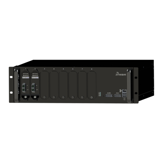
Page 30: Primary Hub
UniTransport Hub, may be coupled via fiber to the rear slots of other downstream Primary Hubs. Front View Number Description Slots1 to 8 for Optical Modules or Transport Modules Ethernet connector USB Connector (Type A) USB Connector (Type A) Copyright © 2022 Zinwave. All rights reserved. - Page 31 UNItivity 5000 Understanding the Components User Manual RS232 Connector Alarm Connector (9 way D-type) Status LEDs Handle and Mounting Bracket (both sides of device) Copyright © 2022 Zinwave. All rights reserved.
-
Page 32: Secondary Hub
The Secondary Hubs can be co-located with the Primary Hub or distributed throughout the site as appropriate. Copyright © 2022 Zinwave. All rights reserved. -
Page 33: Service Module
Up to 4 Service Modules can be deployed in the back of a Primary Hub. Number Description Status LEDs RF Input N type RF Output N type Retaining Screw Copyright © 2022 Zinwave. All rights reserved. -
Page 34: Optical Module
Secondary Hubs or Remote Units with no impact to service. Optical Modules are intended to connect only by optical fiber. Front View Number Description Status LEDs Optical Fiber connector (Duplex SC-APC/SC- APC connector) Retaining Screw Optical Modules are intended to connect via Zinwave patch cords. Copyright © 2022 Zinwave. All rights reserved. -
Page 35: Transport Module
Primary Hub. It is not permitted to fit Transport Modules into both front and rear of the same Primary Hub. Front View Number Description Status LEDs Optical Fiber connector (Duplex SC-APC/SC- APC connector) Retaining Screw Transport Modules are intended to connect via Zinwave patch cords. Copyright © 2022 Zinwave. All rights reserved. -
Page 36: Remote Unit
Hubs, and receives and amplifies signals from smart phones, tablets, laptops, and other hand-held devices. Bottom View Number Description Phoenix Contact 5.08mm Connector 3-way: Alarm Relay Phoenix Contact 5.08mm Connector 2-way: 48V DC Input Optical Fiber connector (Duplex SC-APC/SC-APC connector) Copyright © 2022 Zinwave. All rights reserved. -
Page 37: Antennas
Remote Unit. The system uses a laser in the transmit direction and photodiode in the receive direction. UNItivity 5000 is intended to be deployed with Single-mode fiber infrastructure. Zinwave supplies various fiber patch cords with the correct duplex SC-APC/SC-APC terminations for the Zinwave UNItivity equipment, and other optical connectors as required to match the installed infrastructure. -
Page 38: Hub And Module Leds
Secondary Hub successfully associated with PH, but there are Flash no fully operational Remote Units attached. Green Secondary Hub successfully associated with Hub, and there is at least 1 fully operational Remote Unit attached. Copyright © 2022 Zinwave. All rights reserved. 3-10... -
Page 39: Optical Links To 8X Remote Units
Optical Module. Only when a Remote Unit is detected will the third LED be activated. A fully functioning Optical module with operational downstream elements displays three green LEDs. Copyright © 2022 Zinwave. All rights reserved. 3-11... -
Page 40: Power Led-Right
Flashing Flashing Orange RF Path Calibration or RF System Check in progress Orange Optical calibration and auto-setup Error – For Possible Not Used causes refer to “System Status” page on GUI Copyright © 2022 Zinwave. All rights reserved. 3-12... -
Page 41: Start-Up Sequence
Optical calibration and auto-setup of downstream units in Flash progress, and/or one or more downstream Remote Units have their radio transceivers disabled. Green Green Green Optical Module and all downstream system elements operating normally. Copyright © 2022 Zinwave. All rights reserved. 3-13... -
Page 42: Transport Module
UniTransport Hub. Green Potential failure state: Hardware Warning Alarm is Flash present on this Transport Module. Green Green Transport Module is connected to active upstream UniTransport Hub. Copyright © 2022 Zinwave. All rights reserved. 3-14... -
Page 43: Remote Unit Leds
Alarm active Alternate Red/ Associating with Hub Green Green Flash Unit successfully associated with Hub. Optical link calibration and auto-setup in progress, and/or Remote Unit radio transceiver disabled. Green Remote Unit fully operational Copyright © 2022 Zinwave. All rights reserved. 3-15... -
Page 44: Performing A Basic Installation
10) Access the GUI and view status pages (See section Primary Hub software is the latest version. Perform software upgrade if needed. “System 11) Set up the system based on the coverage tool and measured inputs. (See section Setup”). Copyright © 2022 Zinwave. All rights reserved. -
Page 45: Installing And Populating Hubs
PC Case 128-0113 M6 Cup Washer Black Mounting Bracket washers 128-0112 Screw M6x12 PAN POZI Hub Mounting Screws STL Black (suitable for M6 Cage nuts, not supplied) Power Cord Country specific power cord Copyright © 2022 Zinwave. All rights reserved. -
Page 46: Standard 19" (48.26Cm) Rack Mounting
The following tools are required for installation (Not provided): • 4x M6 cage nuts appropriate for 19 inch rack frame • Pozi-drive screwdriver • Washers and Screws, suitable for Rack type, to secure equipment Copyright © 2022 Zinwave. All rights reserved. -
Page 47: Installing Blank Panels
For example, if you are using slots 1 to 4, place blank plates on slots 5 to 8. 21) Insert a retaining screw in the hole and turn to hand-tighten. Copyright © 2022 Zinwave. All rights reserved. -
Page 48: Installing Secondary Hub
Installing and Populating Hubs User Manual 5.2 Installing Secondary Hub The Secondary Hub is designed to mount directly into a 19-inch rack framework with no additional mounting materials. Below dimensions are in millimeters. Copyright © 2022 Zinwave. All rights reserved. - Page 49 UNItivity 5000 Installing and Populating Hubs User Manual Copyright © 2022 Zinwave. All rights reserved.
-
Page 50: Installing Service Modules In Primary Hub
“Primary Hub Front Panel LEDs” 5. If power is applied before insertion, see for LED descriptions. Note: LEDs will only fully function when equipment on the other end of the fiber is present and working. Copyright © 2022 Zinwave. All rights reserved. -
Page 51: Installing Optical Modules In Primary Hub
Primary Hub Set Up page of the Configuration GUI once the system is correctly configured. Although modules may be hot swapped, during initial installation it is recommended that the Primary Hub power is switched off until the initial module installation is completed. Copyright © 2022 Zinwave. All rights reserved. -
Page 52: Powering The Secondary Hub
1. Plug the AC power cord into the front of the Secondary Hub and into an AC power outlet. 2. Verify the LED status shows correct start up sequence (Flashing red, flashing green, stable green) and the equipment is ready for operation. Copyright © 2022 Zinwave. All rights reserved. -
Page 53: Installing Remote Units
Remote Unit • Zinwave Patch Cords • Mounting Bracket • 4x M4 screws • RAWL Plugs 6.1.1 Considerations before Mounting The Remote Unit (with mounting bracket) has the following dimensions displayed in millimeters: Copyright © 2022 Zinwave. All rights reserved. - Page 54 The holes selected should be sufficiently separated. Use one of the hole patterns shown below, or a pattern derived from one of these 2 patterns where each screw may be moved to an adjacent position. Copyright © 2022 Zinwave. All rights reserved.
- Page 55 Remote Unit in place. If the Remote Unit needs to be removed, then hold the Remote Unit on both sides with fingers reaching behind to press the central release buttons on the mounting bracket, allowing the Remote Unit to be ‘unplugged’. Copyright © 2022 Zinwave. All rights reserved.
-
Page 56: Powering Remote Units
PSU. 2. Place the PSU into the rack and secure using suitable mounting screws and washers. While a power lead is not supplied inside the box as shipped – Zinwave does provide the country Note: specific power lead in with the shipment where PSU are required by the customer. -
Page 57: Das Installation Considerations
Remote Units see 7.1.1 Isolation The minimum isolation between Tx and Rx required for correct operation of UNItivity 5000 in both the uplink and downlink service bands is usually 40dB (this requirement should be confirmed for any given installation within the Zinwave Coverage Tool). -
Page 58: Uplink/Downlink Balance
This is usually done in the head-end by moving attenuation from the uplink to downlink paths. However, in some case the UL/DL balance setting can also be used within the UNItivity 5000 platform if the uplink gain is not already at maximum. •... -
Page 59: Connecting The Psu Or Secondary Hub Power Port To Remote Units
The Phoenix Contact connectors used on the Zinwave equipment support wire thickness up to AWG 12. The guidance for the maximum distance that can be achieved for given AWG wire is as follows, when a single Remote Unit is powered with a single conductor pair. -
Page 60: Understanding Connectors & Cabling
Ensure the 48V connection is made with correct polarity. Note: If you use your own 48V power supply, rather than the Zinwave Remote PSU or Secondary Hub, the cable instructions are the same as for the Zinwave equipment. -
Page 61: Uplink System Noise
(measured or calculated) The Noise contribution of the Zinwave Active DAS is related to the amount of equipment in the system. It is proportional to the additive noise power from each Remote Unit. It can be calculated from: NF= 14 + 10 x LOG (SQRT(qty of RUs)) + 10 x LOG (SQRT(qty of SHs)) This an empirical formula that gives a “best fit”... - Page 62 UL POI attenuation calculated from that value. Comparing calculated Noise floor against that measured will also confirm that no other issues are causing a higher than expect noise floor output from the DAS Copyright © 2022 Zinwave. All rights reserved.
-
Page 63: Unitransport
UniTransport Hub. If the number of connected RUs were to be doubled from 64 to 128, expect the noise power at the BTS to increase by 3dB. As before, the POI UL attenuation would need to be adjusted to achieve a compliant uplink noise power at the BTS. Copyright © 2022 Zinwave. All rights reserved. -
Page 64: Performing Basic Configuration
To Configure UNItivity 5000 : 1. The Zinwave Coverage Tool is used to plan the system and calculate the setting required for its deployment. Gather all needed input information generated by the coverage tool and any measured signal input powers. -
Page 65: Understanding The Configuration Gui
In order to access the GUI in this state, the simplest method is to use a direct ethernet connection from a standalone PC. To do this, you need to match the PC’s IP address to the same subnet as the default Primary Hub address. Copyright © 2022 Zinwave. All rights reserved. - Page 66 2. Make an Ethernet connection from the standalone PC to the Primary Hub (either a crossover or straight-through Ethernet cable can be used). “Accessing the GUI” 3. Access the GUI as described in and go to the Hub Setup page to “IP change the IP address. See Settings”. Copyright © 2022 Zinwave. All rights reserved.
-
Page 67: Accessing The Gui
Certificate. You may need to select advanced options to see all acceptance options. 7. The Login window appears (browser specific.) 8. Enter the username and password. There are three privilege levels available. Copyright © 2022 Zinwave. All rights reserved. - Page 68 Maintenance System Can open and view all System Views. Views Can save System Snapshot Report. (Same as an “advanced” user.) Actions No privileges to Save or Load configuration. (Dropdown) Cannot Download System Tables. Copyright © 2022 Zinwave. All rights reserved.
-
Page 69: Understanding The Main Window
9.4.2 Login Bar The login bar shows the Primary Hub label (if set) and who is logged into this application. 9.4.3 Help Button The Help Button is available on the right side of the screen. Copyright © 2022 Zinwave. All rights reserved. -
Page 70: Display Area
Throughout the use of the application, the progress indicator is displayed. This indicates that the system is gathering or calculating information. When the task is complete, the desired information or page is displayed. Copyright © 2022 Zinwave. All rights reserved. -
Page 71: Changing User Passwords And Timeouts
The Current user is shown in the Security Settings pane. 2. Select the desired number of minutes from the Inactivity Timeout pulldown in the Security Settings pane to set the period of inactivity in the Configuration GUI before forcing a logout. Copyright © 2022 Zinwave. All rights reserved. - Page 72 Advanced users can also choose to “keep me Logged in”. 3. To change a user password… 1. Select the user type password to change from the pulldown. 2. Enter a new password 3. Re-enter the new password. 4. Click Update. Copyright © 2022 Zinwave. All rights reserved.
-
Page 73: Initial System Setup
Equipment is shipped with the latest version of software at the time of manufacture. However, updates may have been made after shipping. The latest version of software is always available via your Zinwave supplier or from the support area on our website https://portal.zinwave.com/portal-gateway/... - Page 74 Once all required Hub and Remote Unit transfers have reached 100%, software / firmware installation will proceed according to the “Auto-install after transferring” setting. The “Install” button will be made available and can be selected to initiate the software installation process manually. Copyright © 2022 Zinwave. All rights reserved. 10-2...
-
Page 75: To Update Ru And Sh Firmware From An Installed Primary Hub Software
POI hardware that feeds the Service Module. It is declared as the Calculated Input Level (dBm) at the Service Module input. Services may also be brought to the hub over fiber using a Transport Module in a rear slot. The Copyright © 2022 Zinwave. All rights reserved. 10-3... -
Page 76: Service Module Downlink Agc
Input AGC Threshold is set to +5 dB, then the Primary Hub will limit the downlink signal level internal to the Transport Module to -20 dBm by dynamically dialing in additional attenuation in the Transport Copyright © 2022 Zinwave. All rights reserved. 10-4... -
Page 77: Rack-Mount Power Supply Unit Configuration
Hub, that don’t have an accessible Secondary Hub power port. This section allows the user to configure a Zinwave RM-PSU that has been connected to a USB port on the Primary Hub. Clicking on the green icons for each power port and then clicking Apply will configure the power state of the power ports. - Page 78 The settings applied from the System Setup screen are literally applied for any services above 1575 MHz. Any services that lie below 1575 MHz will experience approximately 3 dB lower Downlink and Uplink gain. Copyright © 2022 Zinwave. All rights reserved. 10-6...
-
Page 79: System Status
In this page, the user can “Download Event Log” as an event/log text file and “Download System Log” as a rawlog.zip compressed text file. This zipped file contains at least 15 minutes of system logging Copyright © 2022 Zinwave. All rights reserved. 10-7... -
Page 80: Hub Setup
“Download System Log” button being clicked. System Logs may be sent to Zinwave to facilitate diagnosis of system issues. System Logging is disabled by default and should be enabled only where a problem is suspected. -
Page 81: User Interface Settings
Select your Time Zone from the pre-defined drop-down list. Ignore the "Custom TZ String" field if your Time Zone is available. If your Time Zone is not available please contact Zinwave, who will provide a custom TZ string. Note: Any change to the Date & Time configuration will result in the Hub restarting. -
Page 82: Alarms Setup
System Check performs a system-wide scan to measure the RF isolation between TX and RX antennas on the same Remote Unit, as well as between the neighboring Remote Units. It also checks Copyright © 2022 Zinwave. All rights reserved. 10-10... -
Page 83: System Views
This View lists all units/modules for which the count of any alarms is non-zero (the Alarm Count is a cumulative number for all the instances of an alarm since the last system restart). Copyright © 2022 Zinwave. All rights reserved. 10-11... -
Page 84: Link Quality
If cross-coupling is in the range -50 to -45dB it is shown as amber; stronger than -45dB is it red. Strong coupling from one RU’s Tx to another RU’s Rx is not to be expected. Copyright © 2022 Zinwave. All rights reserved. 10-12... - Page 85 UNItivity 5000 Initial System Setup User Manual Sample RF System Check View showing two RUs amber highlighted “Tx/Rx Antenna Isolation (dB)” values due to the “>=” prefix. Copyright © 2022 Zinwave. All rights reserved. 10-13...
-
Page 86: Additional System Setup
11.3 Changing or Swapping Equipment If equipment is removed from an existing system, the system will recalibrate links and apply stored Copyright © 2022 Zinwave. All rights reserved. 11-14... -
Page 87: Hub
To reset a Hub to factory settings: 1. Using a small device (such as an open paper clip), push the Reset button located on the front of the Hub and hold in for 10 seconds. Copyright © 2022 Zinwave. All rights reserved. 11-15... - Page 88 • Sub Net: Default 255.255.255.0 • Gateway: Default 192.168.0.1 • Passwords: Advanced: supervisor • NTP Settings: default disabled • Alarm Settings: default condition Fault Configure as desired as described throughout this manual. Copyright © 2022 Zinwave. All rights reserved. 11-16...
-
Page 89: Unitransport System Setup
One UniTransport Hub may be connected to multiple downstream Primary Hubs, and any Primary Hub may be served by multiple UniTransport Hubs. However, no further cascading is supported – i.e. no hub may have Transport Modules fitted to both front and rear slots simultaneously. Copyright © 2022 Zinwave. All rights reserved. 12-17... -
Page 90: Configuration Of Unitransport Hub
UniTransport Hub and the downstream Primary Hub need gain settings that add up to 20dB. To make it as simple as possible, the hub software calculates all the settings from your input of the power level that is to be sent over the fiber. Copyright © 2022 Zinwave. All rights reserved. 12-18... -
Page 91: Configuration Of Downstream Primary Hub
UniTransport System Setup User Manual Zinwave recommends that the DL IP power presented to the Downstream PH is set to -25dBm. Also set the UL AGC Threshold to a little higher than this, -20dBm is recommended. The settings are calculated when you click Validate Settings, and applied to the hardware when you then click the Apply Settings button. -
Page 92: Remote Configuration Of Unitransport Hub
Clicking the Setup button for a given Transport Module will open a new tab or window in the browser to show the services routed to that Transport Module. Clicking Apply Settings will send any changes back to the UniTransport Hub. Copyright © 2022 Zinwave. All rights reserved. 12-20... - Page 93 The Services provided by the UniTransport hub may also be routed to its own Secondary Hubs and Remote Units as well as other hubs, so keep in mind that changing any power levels and switch settings will have a wider effect. Copyright © 2022 Zinwave. All rights reserved. 12-21...
-
Page 94: Understanding Alarms & Reporting
Service as desired and some services will Check that each Matrix has valid input Module, or by matrix not be present due to incomplete and output paths set settings Matrix settings. Copyright © 2022 Zinwave. All rights reserved. 13-22... -
Page 95: Service Warning
The requested composite System Setup cannot be achieved. Check Optical connections and link power could not be This will be due to a poor optical quality. achieved link which requires too much compensation (gain). Copyright © 2022 Zinwave. All rights reserved. 13-23... - Page 96 Service power of a Service Module output level of the Service module Module exceeds the limit, resolve it by (+5dBm). lowering the Uplink/Downlink balance setting on the affected service Copyright © 2022 Zinwave. All rights reserved. 13-24...
-
Page 97: Hardware Warning
PSU. equipment. See specific over and The module under temp alarms below. temperature is below The cause will be the ambient the limit temperature of the device in question. Current1 over limit Copyright © 2022 Zinwave. All rights reserved. 13-25... - Page 98 Remove the overload condition above the upper limit conjunction with a Remote Unit indicates that the overload value for the RU has been exceeded. Copyright © 2022 Zinwave. All rights reserved. 13-26...
-
Page 99: Informational
These are for information only and will not raise an alarm. 2020-04-01 11:33:22: New System Setup being set by: advanced. Copyright © 2022 Zinwave. All rights reserved. 13-27... -
Page 100: Alarms Setup
Clicking the Cancel button cancels all changes and returns to the Alarms Setup page. 13.3 Alarm Connections UNItivity 5000 can connect to external alarm sources or monitors via the 9-way D-type connector on the Primary and Secondary Hubs. The connector provides 4 relay outputs: normally open alarm;... -
Page 101: Snmp
1. The hub3000 section supports an SNMP V2 MIB interface, which offers simple polling of the alarm relay state and current fault description. This section is compatible with earlier Zinwave 3000 DAS products. The definition for this interface is provided in the ZINWAVE-MIB file (supplied as zw5000-5.14_mib.txt) -
Page 102: Snmp Trap Events
Hub3000Objects.Hub3000String – This is the label of the Hub, as has been set in System Setup. • Hub3000Objects.Hub3000DeviceType – This is the type of UNItivity 5000 unit. • Hub3000Objects.Hub3000ModelName – This is the model name of the UNItivity 5000 unit. • Hub3000Objects.Hub3000FaultRelayState – The state of the fault relay, either set(1) or cleared(0). •... -
Page 103: 3000 Snmp Traps
• unitivity5000FaultRelayStatus • unitivity5000DASoperationalStatusChange • unitivity5000ServiceLossOfServiceChange • unitivity5000RUconfigLossOfServiceChange • unitivity5000ModuleLossOfServiceChange • unitivity5000ModuleServiceWarningChange • unitivity5000ModuleHardwareWarningChange • unitivity5000NotificationsLost • unitivity5000RMPSUAlarmsChange Which replace similar notifications in ZINWAVE-MIB and should be used in the same manner Copyright © 2022 Zinwave. All rights reserved. 13-31... - Page 104 UNItivity 5000 Understanding Alarms & Reporting User Manual Copyright © 2022 Zinwave. All rights reserved. 13-32...
-
Page 105: Performing Diagnostics And Testing
14.1.1 Diagnose an Optical Link In presence of high levels of back reflection due to poor Return loss, the Zinwave system performance is degraded. The effects of this can be easily seen on the system and diagnosed using appropriate test equipment. -
Page 106: Led Testing
Dull Red to allow Module detection Module detected and full power Green connected to module Green Calibration complete, but final output Flash Green Green stage not enabled Green Green Green Fully operational Copyright © 2022 Zinwave. All rights reserved. 14-2... -
Page 107: Remote Unit Led Test
OFF – RED – ALT. RED/GREEN – GREEN FLASH – GREEN 2. Using “System Setup” disable the Remote Unit output a. The LED will FLASH GREEN 3. Using “System Setup” re-enable the Remote Unit output a. The LED will go GREEN. Copyright © 2022 Zinwave. All rights reserved. 14-3... -
Page 108: Event Log
14.3.2 System Logging System Logs are stored on the Hub’s internal flash memory and can be sent to Zinwave for more detailed fault-finding. System Logging is commenced by clicking the “Start System Logs” button and is stopped by clicking the “Stop System Logs” button. Alternatively, the system will automatically stop System Logging after 1 week to avoid excessive flash memory wear. -
Page 109: Specifications
Number of optical ports Up to 8 duplex ports supported on Primary Hub (Optical Modules); 9 duplex ports on Secondary Hub; 1 duplex port on Remote Unit; SC-APC / SC-APC connectors Wavelength 1310 nm Copyright © 2022 Zinwave. All rights reserved. 15-1... - Page 110 Alarm Relay connections: 1 DB-9 female connector Remote Unit RF Antenna connections: 2 N-type female connectors Optical interconnect: duplex fiber SC-APC connector Alarm Relay connector: 1 Phoenix Contact 5.08 mm 3-way male Copyright © 2022 Zinwave. All rights reserved. 15-2...
Need help?
Do you have a question about the UNITIVITY 5000 and is the answer not in the manual?
Questions and answers