Table of Contents
Advertisement
Installation & User Instructions
CellCOM PRIME Standalone GSM Range
PROFESSIONAL INSTALL ONLY
Suitable for Firmware Version 2.2.3
The manufacturer cannot legally offer technical support to non-qualified gate
or door installers. End users should employ the services of a professional
install company to commission or support this product!
Tip: Site Survey BEFORE you begin.
See pages 3-4
P a g e
| 1
Advertisement
Table of Contents

Subscribe to Our Youtube Channel
Related Manuals for AES global CellCOM PRIME


Summary of Contents for AES global CellCOM PRIME
- Page 1 Installation & User Instructions CellCOM PRIME Standalone GSM Range PROFESSIONAL INSTALL ONLY Suitable for Firmware Version 2.2.3 The manufacturer cannot legally offer technical support to non-qualified gate or door installers. End users should employ the services of a professional install company to commission or support this product! Tip: Site Survey BEFORE you begin.
- Page 2 Index Section Pages PHASE 1 – SITE SURVEY 3 - 4 Site Survey (LAN) PHASE 2 – PRODUCT OVERVIEW 5 – 22 Overview of Call Points 6 - 11 More Detail…. 12 - 17 PCB Module Overview 18 – 19 Sellable Code Table Technical Specifications 21 - 22...
- Page 3 PHASE Site Survey P a g e...
-
Page 4: Important Things You Need To Know
Important things you Need to Know.. To be installed by certified and qualified Please read this entire manual before installing this product. personnel / gate automation dealer only. Not for DIY install! Set up, on a bench in the workshop Ensure there is a good 4G signal on site. - Page 5 PHASE Product Overview P a g e...
- Page 6 Overview of Switches Antenna Integrated P a g e...
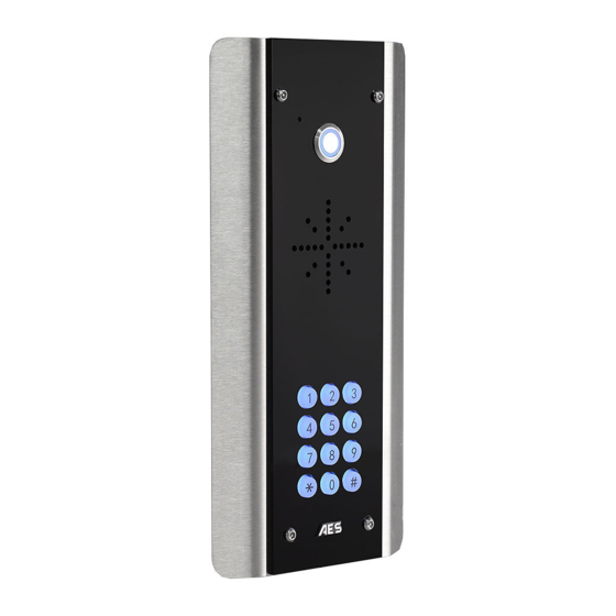
- Page 7 Overview of Intercoms (Architectural Design) Antenna Separate P a g e...
- Page 8 Overview of Intercoms (Imperial Design) Antenna Separate P a g e...
- Page 9 Overview of Intercoms (Pedestal Design) Antenna Integrated P a g e...
- Page 10 Overview of Intercoms (Flush Design) Antenna Separate P a g e | 10...
- Page 11 Overview of Intercoms (ARC Design) Antenna Separate P a g e | 11...
- Page 12 More Detail…. GSM Switch Note: the numbers in the brackets (#) relate to the sellable code table on page 20 Security Screw Access GSM Assembly (2) Mounting Plate (1) P a g e | 12...
- Page 13 Architectural Model Microphone (10) Side Illumination Security Screw (12/13) Access DDA LED’s (PROX version only) Optional PROX Reader (11) Waterproof Mylar 1.5W Speaker (9) Optional Illuminated IP67 Illuminated Push Button (5/6) Keypad. (14/15) Side Illumination Board (12/13) Mounting Holes Cable Entry Hole Optional Keypad (14/15) &...
- Page 14 Architectural Model (No Touch) Microphone (9) Security Screw Side access Illumination (12/13) Illuminated IP67 Contactless Sensor (7) Waterproof Mylar 1.5W speaker (9) Optional PROX Reader (11) Mounting Holes Cable Entry Hole Optional PROX Module & Coil Assembly (11) Sensor (7) Speaker Module (9) Due to the nature of a contactless sensor in replace of a physical button and if using the panel...
- Page 15 Imperial Version Security screw Powder access coated hood Waterproof Mylar Optional PROX 1.5W speaker ( reader (11) Optional illuminated keypad. Illuminated IP67 (14/15) push button (5/6) Microphone (10) Mounting holes Cable entry hole Optional Keypad (14/15) & PROX module (11) GSM Assembly Call button (5/6) Prox Coil...
- Page 16 Imperial Version (multi-button) Security Screw Access Illuminated Nameplate Windows Waterproof Mylar Illuminated IP67 1.5W Speaker (9) Push Buttons (8) LED’s Optional Illuminated Keypad. (14/15) Optional PROX Reader (11) Microphone (10) Mounting Holes Cable Entry Hole Optional Keypad (14/15) & PROX Module (11) Assembly (2) Call Buttons Prox Coil...
- Page 17 Pedestal Version GSM Antenna Cam Security Lock (16) Speaker Module (9) Microphone (10) Call Button (5/6) Optional PROX Reader Optional (11) Keypad (14/15) GSM Antenna Pedestal Mounting Holes PROX Coil Call Button (5/6) (11) GSM Assembly Optional Keypad (14/15) & PROX Module (11) Cam Security Lock (16)
- Page 18 Main GSM Module (2) in Detail… White LED = NANO SIM Green LED = CPU Status Modem Status holder Blue LED = Signal Status Female SMA Antenna Connection Red LED = Power Microphone Speaker USB-B Port Relay 1 8.000 Relay 1 Relay 2 Relay 2 DC 24V...
- Page 19 Overview of Surge PCB (4) *optional extra Earth Rod MUST be connected for warranty. Power Output NOT USED 24v INPUT – Use provided power supply or hook up to 24v solar system. (DO NOT USE 12v HERE) 12v DC – Battery backup 1 Amp Quick Blow Input Fuse (REPLACEABLE) Must use a 30 Watt solar panel (minimum) and at least 2 x 10Ah batteries to supply a regulated 24v...
- Page 20 Component Sellable Codes Component Sellable Code iGate Prime PCB I-PCB 4G Prime PCB Prime7AB-PCB-EU Multibutton PCB MC-NP-MB Surge PCB SURGE3 Blue push button BPB-24V White push button WPB-24V No touch sensor NT-BUTTON Multibutton buttons ECO-BUTTON Speaker SPK-ASSM GSM mic Prox PCB and coil PROX-PCB-PRIME6 Backlighting PCBs (blue) LEDB-PCBA-ABK-V2...
-
Page 21: Technical Specifications
Technical Specifications GENERAL Front Panel Portrait Orientation AB/ABK = 3mm Acrylic on Architectural Design Marine Grade Stainless Steel BS316 Front Plate AS/ASK = 3mm Marine Grade Stainless Steel BS316 on Architectural Design Marine Grade Stainless Steel BS316 Front Plate FS/FSK = Flush Design Marine Grade Stainless Steel BS316 Front Plate IMP/IMPK = 3mm Acrylic on Imperial Design Marine Grade Stainless Steel BS316 Front Plate... - Page 22 Baud Rate 9600 / 115200 Code Length 4 Digits (fixed) Confirmation Key Modem Models 4G Europe - SIM7500E Frequency Range GSM900 880-915MHz, DCS 1800 1710-1785MHz WCDMA Band I 11920-1980MHz, WCDMA Band VIII 880- 915MHz LTE B1, B3, B7 1920-9180MHz, 1710-1785MHz, 2500-2570MHz LTE B8, B20 880-915MHz, 832-862MHz RF Output Power (EIRP) 32.55dBm (GSM 900), 29.73dBm (DCS 1800)
- Page 23 PHASE Setup (To be done before installing the intercom) P a g e | 23...
- Page 24 GSM Coverage Before installing this system, you need to be sure that there is good mobile GSM cell coverage in the area it is to be installed. It is recommended that you conduct a site survey, and check reception on the site for GSM coverage. If reception is poor in the area, then this system is not recommended.
- Page 25 Inserting the SIM card Please ensure the SIM card is a 4G NANO SIM card. Do not use a SIM card for a tablet, as these only support data, and do not support voice and SMS. You simply require a mobile phone type SIM card.
- Page 26 Status LED’s Flashing = standby Constant ON/OFF = busy SIGNAL STRENGTH 1 flash = poor (1 bar) 2 flashes = low (2 bars) 3 flashes = good (3 bars) 4 flashes = Strong (4 bars) 5 flashes = searching POWER MODEM Flashing = standby Constant ON/OFF = searching...
- Page 27 1: Check Reception ‘More > Info’ Go to & press the reception/signal level button. On Android, the app will automatically send an SMS string (*20#) to the intercom. The intercom should then reply with a signal level between 1 and 31. 1-11 12-20 21-31...
- Page 28 1b: Set APN (for VOLTE / 4G service) ONLY REQUIRED FOR DIAL-OUT OPTIONS & CAN BE SKIPPED IF USING THE SIM NETWORK PRESET AS DETAILLED ON PAGE 22 App/SMS If you have network mode showing 3G this feature may need to be set to achieve full 4G network ‘Manage >...
- Page 29 PHASE Installation P a g e | 29...
- Page 30 How to Achieve & Maintain IP55 Rating The IP55 rating attached to this unit is only achieved if the below steps have been followed. This is to prevent any unwanted water and/or bug ingress that can cause various issues with functionality and will void the warranty if not followed. Step 1 –...
-
Page 31: Solar Power
Power This intercom comes with a 24V dc power supply. The intercom requires up to 2 amps peak demand at times, therefore power cable is of extreme importance. Using insufficient power cable thickness will cause excessive stress on electronic components, and can therefore void the manufacturer’s warranty. -
Page 32: Battery Backup Option
Battery Backup Option If you wish to prevent your intercom from losing power in the event of a power outage, we recommend using a battery backup. Diagrams below are for demonstrational use only POWER ON DC Power Adapter Voltage Backup Battery Switching Module Power Supply... - Page 33 Inserting the SIM card 45 chamfer IN Pads DOWN WARNING Ensure power is OFF. Do not hot Ensure SIM is activated. insert or remove while power on Pre-pay SIM will need credit first. Powering Up Perform a final check of wiring and ensure the antenna is connected before switching on the power.
- Page 34 Relay Wiring Examples Driveway Gates Gate Controller Relay1 Note: manufacturer is Optional not responsible Separate Exit Button lock PSU for wiring to Relay 2 PRESS third party devices. Please TO EXIT consult the device instructions if having issues. Magnetic Lock Additional Wiring Tips Relay STRIKE...
- Page 35 Connecting Slave Devices Colour code is *Keypad module required* SLAVE OUT for illustration purpose only. SLAVE IN Terminals are 12-24v 1 2 3 black SLAVE IN 12-24v Jumper SLAVE IN Link Cover SL AVE OU T SLAVE IN/OUT SL AVE IN SLAVE OUT 12-24v 1 2 3...
- Page 36 Auxiliary Device Relay Setup Relay 3 Relay 4 Relay 5 Dip switch configuration for relays 3 to 8 on auxiliary Relay 6 Relay 8 Relay 7 devices. sounder boards dip switches relay number for auxiliary unit it is in. The dip switch of the prox must SLAV E IN match the dip switch configuration of the auxiliary it wants to trigger...
- Page 37 Connecting Slave Devices generation) *Keypad module required* CAT5 (30ft max) Optional Slave 300ft if device powered separately Keypad 1 2 3 24v Optional Keypad To next device 1 2 3 24v 1 2 3 24v Optional Slave Prox To next device Reader 1 2 3 24v Optional Prox...
- Page 38 PHASE Programming the Intercom TIP: If you have already set the APN as instructed during configuration this can be skipped. P a g e | 38...
- Page 39 1b: Set APN (for VOLTE / 4G service) ONLY REQUIRED FOR DIAL-OUT OPTIONS iii) App/SMS If you have network mode showing 3G this feature may need to be set to achieve full 4G network ‘Manager > service. Check the APN of your provider (can usually be found online) and then go to APN’...
- Page 40 QR code or search “AES Global” This QR code will take you directly to the Prime playlist on our YouTube channel which will take you through the setup and use of our new AES PRO app for a Prime system.
-
Page 41: Using The Intercom
PHASE Using the Intercom (Only to be done after the unit is successfully programmed) P a g e | 41... - Page 42 Calling a Resident Single Button Multi-Button 1: Press the Call Button 1: Press the Call Button Tip: Press the call button again to cancel a call Using Keypad Codes & Prox IDs (Keypad / Prox Units) Hold Tag / Card up to the Prox reader 1: Enter 4 digit code.
- Page 43 Receiving A Call and Opening Gates / Door Visitors can press the call button, which will initiate a call from your intercom to the designated phone numbers which will have been programmed by your installer. 1. Visitor press the call 2.
- Page 44 Manager Controls of Gate / Door This screen allows the installer or manager to manually trigger the gate. Trigger Send trigger command [Call / SMS] Latch Hold open Gate / Door [SMS] unlatch Release held open gates to close. [SMS] Output Options P a g e | 44...
- Page 45 PHASE Aftercare P a g e | 45...
-
Page 46: Complete List Of Parameters
Complete list of parameters For a complete list of programming, SMS parameters check out our downloadable resources on our website. Troubleshooting Q. The unit will not power up. No LEDs on. A. Check power supply voltage at intercom is 23.4v DC or more. Cable length from PSU to intercom should be less than 25 feet and in 14 gauge for longer distances. - Page 47 Q. The Android App shows an error message “Command Failed” when I try to use a function. A. Go to phone settings/application manager/cellcom prime/permissions, and ensure all permissions are turned ON. Also, ensure the app settings screen has a valid phone number stored.
- Page 48 Q. Forgot Engineers code for SMS programming A. You will need to complete a hard reset by following the steps below. Note this will erase all data stored on the PCB. 1) Power off the unit. (approx 60 secs) 2) Link the terminals marked OPEN. 3) Switch on the power.
-
Page 49: Firmware Updates
Firmware Updates Option 1: FOTA (Firmware Over The Air) FOTA allows you to update your intercom wirelessly without a PC. First, you should check the firmware version on your intercom with *20#. If the firmware doesn’t have (FOTA) after it, then the firmware will need updated to enable this feature (see overleaf). - Page 50 Option 2: Manually Update Via Laptop and USB B Cable Firmware updates will be released to fix any bugs or to add additional features where possible throughout the products lifetime. The firmware version your system is using can be found by sending the system status message (*20#).
- Page 51 (a) Connect USB B-type cable to Windows PC/laptop (Windows 10 or later). (b) Connect USB cable to port as shown below. (This can be done while the unit is powered on). **The intercom will need to be powered on and connected to the cellular network before upgrading can begin** ** Images are for illustration purposes only.** Step 2: Download...
- Page 52 (a) Download the 4G Upgrade Tool from the AES Global website. Found https://aesglobalparts.com/pages/gsm-resources-1 here: (b) Save the zip file to a location of your choice. (c)Right click on the zip file and click ‘Extract Here’. A software to extract the files may be required such as WinZip or 7zip.
-
Page 53: App Updates
(c) Check the latest firmware version on the board. **Available to view on most recent firmwares only.** (d) Click ‘Flash’, locate the firmware file (bin file format), and wait for the upgrade to complete. (e) Close the 4G Upgrade Tool and remove the USB lead from the board. **** 4GKC9D1831V96 ****... -
Page 54: Environmental Information
The crossed-bin symbol marked in your device invites you to use those systems. If you need more information on the collection, reuse and recycling systems, please contact your local or regional waste administration. You can also contact AES Global Ltd for more information on the environmental performances of our products. -
Page 55: Warranty
We are constantly working to produce the highest quality documentation for our products. We welcome your feedback. Send us your comments or suggestions about our online Help, printed, or PDF manuals. Please include the following information with your feedback: • Product name and version number •... - Page 56 Please note, by installing this product, you are accepting the following warranty terms: 1. The manufacturer’s warranty is a “return to base” 2-year warranty from the date of manufacture. This means that any suspected defective components or items are returned to the manufacturer’s agent for investigation and diagnosis and returned at the cost of the customer.
- Page 57 Free Extra 1 Year Warranty If you register with us within 90 days of purchase and provide proof of purchase, you will be eligible for an extra year of warranty. This QR code will take you to the warranty section of our website. You can access the form for the warranty by scrolling to the bottom of the section and pressing the “Extra year warranty”...
- Page 58 LEFT BLANK P a g e | 58...
- Page 59 LEFT BLANK P a g e | 59...
-
Page 60: Regulatory Compliance
Regulatory Compliance EU-RED Declaration of Conformity Manufacturer: Advanced Electronic Solutions Global Ltd Address: Unit 4C, Kilcronagh Business Park, Cookstown, Co Tyrone, BT809HJ, UK We/I declare, that the following equipment (GSM Cellular Intercom System), part numbers: Multiple Model kit part numbers: PRIME6-MULTI-LT-4GE. Complies with the following essential requirements for 2014/53/EU: ETSI draft EN 301 489-1 V2.1.1 (2017-02) (Electromagnetic compatibility) 2280...
Need help?
Do you have a question about the CellCOM PRIME and is the answer not in the manual?
Questions and answers