
Related Manuals for AES global StyluscomV2 Series


Summary of Contents for AES global StyluscomV2 Series
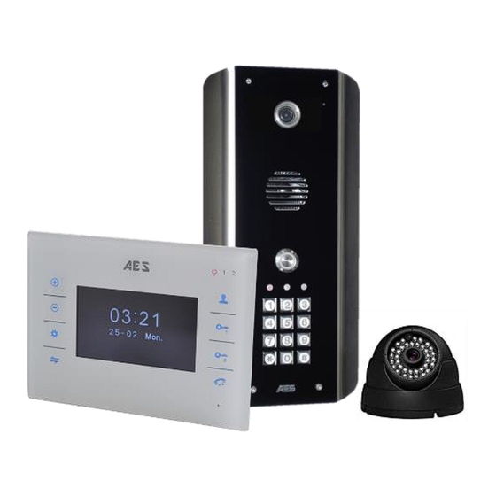
- Page 1 Installation & User Manual StyluscomV2 W ired Video Intercom System Models StylusAB, StylusABK, StylusAS Manual Version 1 P a g e...
-
Page 2: Table Of Contents
Contents …………….Pg 3 Overview of system …………….Pg 3 Site survey …………….Pg 4 Monitor overview …………….Pg 5 Surface mounting the monitor …………….Pg 5 Plasterboard / drywall fixing …………….Pg 6 Door/gate station mounting …………….Pg 7 Wiring gate station to monitor …………….Pg 7 Keypad module in detail …………….Pg 8 Connecting extra monitors... -
Page 3: Overview Of System
Overview of System Please read this entire manual before attempting to install this system. This system should only be installed by a professional automatic gate installer or access control specialist dealer. It is recommended that the system be set up, configured, commissioned and tested on a workshop bench before taken to site for installation. -
Page 4: Monitor Overview
Monitor Overview Monitor mode, Front View change view Increase volume between devices in call Trigger Relay 1 Decrease (Must be in call or volume in call 14.45 monitor mode) 19-02 Tues Settings Trigger Relay 2 (Must be in call or monitor mode) Transfer call Answer/end call... -
Page 5: Surface Mounting The Monitor
Surface Mounting the Monitor Side View Plasterboard / Dry wall Fixing 115mm 165mm Professional install only! Top View Rotate the clips behind the plasterboard with a screw driver, then tighten in place until they gently grip against the plasterboard. After wiring is complete, the monitor can be clipped into place. -
Page 6: Door/Gate Station Mounting
Door / Gate Station Mounting Mount the intercom at the desired height for pedestrian or car users. The camera angle is wide at 110 degrees to cover most scenarios. Loosen top 2 screws only Hinge front door Side View Tip: Do not drill holes in the wall with the intercom in positon, otherwise dust may get around the camera window and impair the camera view. -
Page 7: Wiring Gate Station To Monitor
Wiring Gate Station to Monitor Indoor Monitor Door/Gate Station Camera bypass Camera module Phono input for optional VID1+ external camera VID1- MIC & Speaker CMD1 Volume Adjust (keep to minimum) Relay 2 Micro SD card holder Relay 1 24v DC 24v DC GND Keypad Full/Auto... -
Page 8: Connecting Extra Monitors
Connecting Extra Monitors SLAVE Slave OUT Slave IN ---Data--- ---Video--- MASTER ---Audio--- STATION ----GND---- TIP: CAM2 CAM1 Connect more than 1 to Slave OUT port on master 24v DC SLAVE Slave OUT Slave IN ---Data--- SLAVE ---Video--- ---Audio--- ----GND---- SLAVE TIP: STATION CAM2... -
Page 9: Connecting A Cctv Camera
Connecting a CCTV Camera 12v DC Use standard analogue type camera CAM2 CAM1 CAT5 100m Convertor Balun TIP: One device can have motion detection recording activated in the menu. You may choose between Door1, Door2, Cam1, Cam2 Monitor Settings Toggle/ navigate 14.45 19-02 Tues... - Page 10 (Set language) Language (Set date, date format, and time) Time & Date SYSTEM (Software version, software update, format SD card) Information Ring tone select Ring volume select (can adjust for different time zones) RING MODE Mode Master / Slave (set main monitor to MASTER and all others to SLAVE).
-
Page 11: Answering A Call & Granting Access
Adjust colour, brightness and contrast for connected devices Color Playback recorded video clips (only available if device set in this mode) Record Files View saved snapshots (only available if device set in this mode) Snapshot Answering a Call & Granting Access Viewing Gate/Door &... -
Page 12: Basic Keypad Programming
Basic Keypad Programming For most installs, it is sufficient to simply enter a single user code as follows.. Quick start guide 1) Enter programming mode (amber LED should be ON) 2) Enter a new user code... 3) Exit programming mode 4) Enter the new user code to check the relay clicks. - Page 13 Programming relay output times and modes… 0 = start / stop toggle mode (latching) 51=relay1 Validate 1-99999 = seconds momentary operation 52=relay2 53=relay3 Delete a user code even if you don’t know the code… 10=relay1 Delete code ID location to be deleted Validate 20=relay2 30=relay3...
-
Page 14: Using The Keypad
Using the keypad Using the standard codes… Once you have exited out of programming mode, simply enter the user code. Using super user codes Activate output 1 Activate output 2 Activate output 3 Sound and Volumes With intercoms operating as a loud speaker and the monitor also acting as a loud speaker, it is important to set up the speech volumes carefully. - Page 15 Trouble Shooting TIP: The best way to troubleshoot any problem is by a process of elimination. Try to install one part of a system at a time, check it works, and then add additional monitors and other items one by one. Q: I cannot hear the visitor at the gate/door.
- Page 16 Change History Key: P = Panel version H = Hardware PCB version S = Software version Version Reason for change First version. Second gasket for lens spacing. P a g e | 16...
Need help?
Do you have a question about the StyluscomV2 Series and is the answer not in the manual?
Questions and answers