Table of Contents
Advertisement
weiderfitness.com
Model No. WESY19318.2
Serial No.
Write the serial number in the space
above for reference.
Serial Number Decal (under seat)
REGISTER YOUR
PRODUCT
To register your product and
activate your warranty today,
go to my.weiderfitness.com.
MEMBER CARE
For service at any time, go to
support.weiderfitness.com.
Or call 1-833-680-IFIT
(1-833-680-4348)
Mon.–Fri. 6 a.m.–6 p.m. MT
Sat. 8 a.m.–12 p.m. MT
Please do not contact the store.
CAUTION
Read all precautions and
instructions in this manual before
using this equipment. Keep this
manual for future reference.
USER'S MANUAL
Advertisement
Table of Contents

Related Manuals for iFIT WEIDER 2980 X


Summary of Contents for iFIT WEIDER 2980 X
- Page 1 To register your product and activate your warranty today, go to my.weiderfitness.com. MEMBER CARE For service at any time, go to support.weiderfitness.com. Or call 1-833-680-IFIT (1-833-680-4348) Mon.–Fri. 6 a.m.–6 p.m. MT Sat. 8 a.m.–12 p.m. MT Please do not contact the store. CAUTION...
-
Page 2: Table Of Contents
Apply the decal in the location shown. Note: The decal(s) may not be shown at actual size. This decal is on both sides of the upright and on the pivot frame. WEIDER is a registered trademark of iFIT Inc. -
Page 3: Important Precautions
To reduce the risk of serious injury, read all important precautions and instructions in this manual and all warnings on the weight system before using the weight system. iFIT assumes no responsibility for personal injury or property damage sustained by or through the use of this product. - Page 4 STANDARD SERVICE PLANS...
-
Page 5: Before You Begin
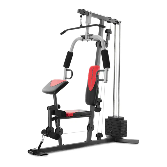
BEFORE YOU BEGIN Thank you for selecting the versatile WEIDER ® 2980 X reading this manual, please see the front cover of this weight system. The 2980 X weight system is designed manual. To help us assist you, note the product model to develop the major muscle groups of the body. -
Page 6: Part Identification Chart
PART IDENTIFICATION CHART Use the drawings below to identify the small parts needed for assembly. The number in parentheses below each drawing is the key number of the part, from the PART LIST near the end of this manual. Note: If a part is not in the hardware kit, check to see if it has been preassembled. -
Page 7: Assembly
ASSEMBLY • To hire an authorized service technician to • To identify small parts, see page 6. assemble this product, call 1-800-445-2480. • In addition to the included tool(s), assembly • Assembly requires two persons. requires the following tool(s): one Phillips screwdriver •... - Page 8 Frame Assembly 2. To make assembly easier, read the information on page 7. Before you begin, make sure that you have: • removed the packaging materials from all of the parts • placed all parts near you in a cleared area •...
- Page 9 4. Attach the Front Leg (7) to the Base (1) with the two M8 x 58mm Carriage Bolts (64) and two M8 Locknuts (58); do not tighten the Locknuts yet. Next, hold the Leg Bumper (60) against the Front Leg (7), and turn the Leg Bumper so that it is angled upward (B).
- Page 10 7. Orient the Top Frame (4) so that the welded support (E) is on the bottom. Attach the Top Frame (4) to the Upright (3) with two M8 x 65mm Bolts (68), two M8 Washers (59), and two M8 Locknuts (58); do not tighten the Locknuts yet.
- Page 11 10. Grease an M8 x 50mm Shoulder Bolt (83). Grease Attach a Cable Pivot (39) to the Left Arm (10) with the M8 x 50mm Shoulder Bolt (83) and an M8 Locknut (58). Do not overtighten the Locknut; the Cable Pivot must pivot easily. Next, wet the inside of a Large Foam Pad (42) with soapy water.
- Page 12 13. IMPORTANT: Identify the two V-pulleys (46), the nine Pulleys (48), and the two Thin Pulleys (47). Tip: It may be helpful to refer to the EXPLODED DRAWING near the end of this manual to identify the locations of the pulleys. Route the Arm Cable (54) over a V-pulley (46).
- Page 13 16. Grease an M8 x 20mm Shoulder Bolt (65). Attach the Arm Cable (54) to the indicated Cable Pivot (39) with the M8 x 20mm Shoulder Grease Bolt (65) and an M8 Locknut (58). Make sure that the cable end can pivot easily on the Shoulder Bolt.
- Page 14 19. Route the Low Cable (53) under a Pulley (48) and through the Upright (3). Attach the Pulley (48) inside the Upright (3) with an M10 x 68mm Bolt (71), two M10 Washers (57), two 13mm Spacers (52), and an M10 Locknut (56). 20.
- Page 15 22. Attach the Low Cable (53) to the U-bracket (45) with an M6 Washer (80) and an M6 Locknut (84). See the inset drawing. Do not overtighten the M6 Locknut (84); it should be threaded onto the end of the Low Cable (53) so that only two threads are showing above the Locknut.
- Page 16 26. Route the High Cable (55) upward through the Top Frame (4) and over a Thin Pulley (47). Attach the Thin Pulley (47) inside the Top Frame (4) with the M10 x 68mm Bolt (71) used in step 24, an 10mm Spacer (49), an M10 Washer (57), and an M10 Locknut (56).
- Page 17 Seat Assembly 29. Attach the Backrest (16) to the Upright (3) with two M6 x 65mm Screws (70) and two M6 Washers (80). 30. Attach the Seat (15) to the Seat Frame (6) with four M6 x 16mm Screws (62). 31.
- Page 18 32. Insert the Pad Tube (29) into the Front Leg (7). Next, slide a Small Foam Pad (28) onto each end of the Pad Tube (29). Then, slide a Small Foam Pad (28) onto each side of the Leg Lever (8). 33.
-
Page 19: Adjustment
ADJUSTMENT This section explains how to adjust the weight system. See the EXERCISE GUIDELINES on page 24 for important information about how to get the most benefit from your exercise program. Also, refer to the accompanying exercise guide to see the correct form for several exercises. Make sure that all parts are properly tightened each time the weight system is used. - Page 20 USING THE LEG LEVER To use the Leg Lever (8), pull the Leg Lever Pin (38) out of the Leg Lever and the Lock Plate (73). To use the low pulley station, insert the Leg Lever Pin (38) fully into the Leg Lever (8) and the Lock Plate (73).
-
Page 21: Weight Resistance Chart
LOCKING THE WEIGHT STACK To lock the weight stack, insert the Lock Pin (18) into a Weight Guide (21) and attach the Lock (17) to the Lock Pin. WEIGHT RESISTANCE CHART The chart below shows the approximate weight resistance at each exercise station. The numbers in the left col- umn refer to the 12.5-lb. -
Page 22: Cable Diagram
CABLE DIAGRAM The diagram below shows the proper routing of the cables. The numbers in each drawing show the proper route of that cable. Cut along the dotted line, and refer to this diagram while you assemble the cables and the pulleys. If the cables and the pulleys are not assembled correctly, the weight system will not function properly and damage may occur. -
Page 23: Maintenance
MAINTENANCE Make sure that all parts are properly tightened each time the weight system is used. Replace any worn parts immediately. Use only manufacturer-supplied parts. The weight system can be cleaned with a damp cloth and a mild, non-abrasive detergent; do not use solvents. TIGHTENING THE CABLES Woven cable, the type of cable used on the weight system, can stretch slightly when it is first used. -
Page 24: Exercise Guidelines
EXERCISE GUIDELINES FOUR TYPES OF STRENGTH WORKOUTS to determine the appropriate length of time for each workout, and the numbers of repetitions and sets to Note: A “repetition” is one complete cycle of an complete. Progress at your own pace and be sensitive exercise, such as one sit-up. -
Page 25: Part List
PART LIST Model No. WESY19318.2 R1121A Key No. Qty. Description Key No. Qty. Description Base V-pulley Stabilizer Thin Pulley Upright Pulley Top Frame 10mm Spacer Pivot Frame Cable Trap Seat Frame 50mm x 1.5mm Round Inner Cap Front Leg 13mm Spacer Leg Lever Low Cable Right Arm... -
Page 26: Exploded Drawing
EXPLODED DRAWING A Model No. WESY19318.2 R1121A 56 57... - Page 27 EXPLODED DRAWING B Model No. WESY19318.2 R1121A...
-
Page 28: Ordering Replacement Parts
This warranty extends only to the original purchaser (customer) and is not transferrable. iFIT’s obligation under this warranty is limited to repairing or replacing, at iFIT’s discretion, the product through one of its authorized service providers. All repairs for which warranty claims are made must be preauthorized by iFIT.
Need help?
Do you have a question about the WEIDER 2980 X and is the answer not in the manual?
Questions and answers