Advertisement
Quick Links
proform.com
Model No. PFEL03721.0
Serial No.
Write the serial number in the space
above for reference.
Serial
Number
Decal
REGISTER YOUR
PRODUCT
To register your product and
activate your warranty today,
go to my.proform.com.
MEMBER CARE
For service at any time, go to
support.proform.com.
Or call 1-833-680-IFIT
(1-833-680-4348)
Mon.–Fri. 6 a.m.–6 p.m. MT
Sat. 8 a.m.–12 p.m. MT
Please do not contact the store.
CAUTION
Read all precautions and
instructions in this manual before
using this equipment. Keep this
manual for future reference.
USER'S MANUAL
Advertisement

Related Manuals for iFIT PRO-FORM HYBRID TRAINER


Summary of Contents for iFIT PRO-FORM HYBRID TRAINER
- Page 1 To register your product and activate your warranty today, go to my.proform.com. MEMBER CARE For service at any time, go to support.proform.com. Or call 1-833-680-IFIT (1-833-680-4348) Mon.–Fri. 6 a.m.–6 p.m. MT Sat. 8 a.m.–12 p.m. MT Please do not contact the store. CAUTION...
- Page 2 Note: The decal(s) may not be shown at actual size. PROFORM and IFIT are registered trademarks of iFIT Inc. App Store is a trademark of Apple Inc., registered in the U.S. and other countries. Android and Google Play are trademarks of Google LLC. The Bluetooth ®...
- Page 3 To reduce the risk of serious injury, read all important precautions and instructions in this manual and all warnings on your hybrid trainer before using your hybrid trainer. iFIT assumes no responsibility for personal injury or property damage sustained by or through the use of this product.
- Page 4 STANDARD SERVICE PLANS...
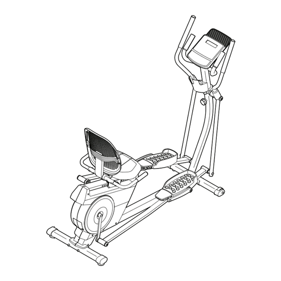
- Page 5 BEFORE YOU BEGIN Thank you for selecting the revolutionary PROFORM ® manual. To help us assist you, note the product model HYBRID TRAINER. The HYBRID TRAINER provides number and serial number before contacting us. The an impressive selection of features designed to make model number and the location of the serial number your workouts at home more effective and enjoyable.
- Page 6 PART IDENTIFICATION CHART Use the drawings below to identify the small parts needed for assembly. The number in parentheses below each drawing is the key number of the part, from the PART LIST near the end of this manual. The number following the key number is the quantity needed for assembly.
- Page 7 ASSEMBLY 1. To use the assembly steps in this manual, first see the helpful tips below. • To hire an authorized service technician to • In addition to the included tool(s), assembly assemble this product, call 1-800-445-2480. requires the following tools: one Phillips screwdriver •...
- Page 8 2. With the help of a second person, place some of the packing materials (not shown) under the Frame (1). Orient the Rear Stabilizer (6) so that the large holes (A) are facing the Frame (1). Attach the Rear Stabilizer to the Frame with two M10 x 80mm Screws (19).
- Page 9 4. Set the Upright (2) near the Frame (1) as shown. Locate the wire tie (C) in the Frame (1), and pull the Main Wire (96) out of the underside of the Frame. Repeat this action to pull the Upper Wire (not shown) out of the underside of the Upright (2).
- Page 10 6. Locate the wire tie (E) in the top of the Upright (2), and pull the Upper Wire (94) out of the Upright. Then, untie and discard the wire tie. Tip: Avoid pinching the wires. Attach the Wire Cover (20) to the Frame (1) and the Upright (2) with two M4 x 16mm Screws (84).
- Page 11 8. Using a plastic bag to keep your fingers clean, apply a generous amount of the included grease to the Pivot Axle (80). Tip: Avoid pinching the Upper Wire (94). Slide the Pivot Bracket (3) onto the Upright (2) and hold it in place.
- Page 12 10. Apply a generous amount of the included grease to the axle on the Right Pivot Leg (8). Then, slide the Right Pedal Arm (9) onto the Right Pivot Leg (8). Attach the Right Pedal Arm with an M8 x 14mm Shoulder Screw (86), a Pivot Cover (83), and an M8 Washer (87).
- Page 13 12. Remove and discard the packaging on the Right Crank Bracket (30). Then, tighten an M8 x 14mm Shoulder Screw (86) with a Pivot Cover (83) and an M8 Washer (87) into the right Crank Arm (24). Next, slide the Right Pedal Arm (9) onto the Right Crank Bracket (30).
- Page 14 14. Identify the Right Upper Body Arm (7). Orient an Upper Body Cover (78) as shown, and slide it upward onto the Right Upper Body Arm (7). Attach the Right Upper Body Arm (7) to the Right Pivot Leg (8) with three M8 x 38mm Hex Bolts (102) and three M8 Locknuts (68);...
- Page 15 16. Attach the Seat Frame (61) to the Seat Carriage (32) with four M6 x 35mm Screws (98); start all the Screws, and then tighten them. 17. Attach the Seat (28) to the Seat Frame (61) with four M6 x 18mm Screws (97) (only two are shown);...
- Page 16 Console (4). Note: If you do not have a smartphone or tablet, use your computer to go to iFIT.com/activate for an alternate way to activate the Console (4). If you do not have a computer, call Member Care (see the front cover of this manual).
- Page 17 HOW TO USE THE HYBRID TRAINER HOW TO PLUG IN THE POWER ADAPTER HOW TO LEVEL THE HYBRID TRAINER IMPORTANT: If the hybrid trainer has been exposed If the hybrid trainer to cold temperatures, allow it to warm to room tem- rocks slightly on perature before you plug in the power adapter (A).
- Page 18 To mount the hybrid trainer in the elliptical mode, hold HOW TO USE THE RECUMBENT BIKE MODE the handlebars (G) or the upper body arms (H) and step onto the pedal (I) that is in the lower position. To use the hybrid Then, step onto the other pedal.
- Page 19 HOW TO USE THE CONSOLE CONSOLE DIAGRAM FEATURES OF THE CONSOLE With the iFIT app, you can access a large and varied library of iFIT video workouts, create your own work- IMPORTANT: To activate your console and begin outs, track your workout results, and access many using its exclusive features, see assembly step 19 other features.
- Page 20 HOW TO USE THE MANUAL MODE Pulse (BPM and heart symbol)—Your heart rate when you use a compatible heart rate monitor (see 1. Begin pedaling or press any button on the step 5). console to turn on the console. Resistance (RESIST)—The resistance level of the When you turn on the console, the display will turn pedals.
- Page 21 To connect a compatible heart rate monitor to the When workout infor- console, press the iFIT Sync button on the console; mation is added, its the console pairing number will appear in the dis- indicator will turn on play.
- Page 22 4. Select an iFIT workout. your smart device and connect it to the console. In the iFIT app, touch the buttons at the bottom of Note: The console supports Bluetooth connections to the screen to select either the main menu (Home smart devices via the iFIT app and to compatible heart button) or the workout library (Browse button).
- Page 23 To connect your Bluetooth Smart heart rate monitor to of calories you burn will be affected. the console, press the iFIT Sync button on the console; the console pairing number will appear in the display. To pause the workout, simply touch the screen When a connection is established, the LED on the or stop pedaling.
- Page 24 To select the settings mode, press the Settings button. The first settings screen will appear in the display. Note: If you are using the manual mode or an iFIT workout, end your workout before you press the Settings button. Total Distance—The letters MI or KM will appear in the display.
- Page 25 MAINTENANCE AND TROUBLESHOOTING MAINTENANCE Next, locate the Reed Switch (60). Slightly loosen the two M4 x 16mm Screws (84). Regular maintenance is important for optimal performance and to reduce wear. Inspect and properly tighten all parts each time the hybrid trainer is used. Replace any worn parts immediately.
- Page 26 HOW TO ADJUST THE DRIVE BELT Next, loosen the M10 x 55mm Shoulder Bolt (99). Then, tighten the M8 Locknut (68) until the Drive Belt If you can feel the pedals slip while you are pedaling, (64) is tight. even when the resistance is adjusted to the highest level, the drive belt may need to be adjusted.
- Page 27 EXERCISE GUIDELINES Aerobic Exercise—If your goal is to strengthen your WARNING: cardiovascular system, you must perform aerobic Before beginning this exercise, which is activity that requires large amounts or any exercise program, consult your physi- of oxygen for prolonged periods of time. For aerobic cian.
- Page 28 PART LIST Model No. PFEL03721.0 R1121A Key No. Qty. Description Key No. Qty. Description Frame Crank Bearing Upright Bearing Spacer Pivot Bracket Crank Collar Console Idler Axle Front Stabilizer Idler Bolt Rear Stabilizer Idler Bushing Right Upper Body Arm Idler Bracket Right Pivot Leg Small Pulley Right Pedal Arm...
- Page 29 Key No. Qty. Description Key No. Qty. Description M10 x 54mm Shoulder Screw Clip Nut M8 x 38mm Hex Bolt Left Pedal Brace Receptacle/Wire Pedal Weight Power Adapter Weight Screw M19 Snap Ring Pedal Brace Bushing M8 x 12mm Screw M10 x 20mm Shoulder Screw Left Small Pedal Pedal Axle...
- Page 30 EXPLODED DRAWING A Model No. PFEL03721.0 R1121A...
- Page 31 EXPLODED DRAWING B Model No. PFEL03721.0 R1121A...
- Page 32 This warranty extends only to the original purchaser (customer) and is not transferrable. iFIT’s obligation under this warranty is limited to repairing or replacing, at iFIT’s discretion, the product through one of its authorized service providers. All repairs for which warranty claims are made must be preauthorized by iFIT.
Need help?
Do you have a question about the PRO-FORM HYBRID TRAINER and is the answer not in the manual?
Questions and answers