Table of Contents
Advertisement
proform.com
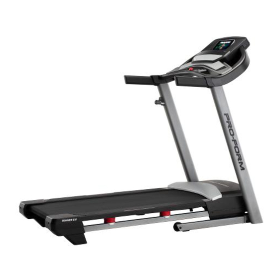
Model No. PFTL69921.2
Serial No.
Write the serial number in the space
above for reference.
Serial Number
Decal
REGISTER YOUR
PRODUCT
To register your product and
activate your warranty today,
go to my.proform.com.
CUSTOMER CARE
For service at any time, go to
support.proform.com.
Or call 1-888-533-1333
Mon.–Fri. 6 a.m.–6 p.m. MT
Sat. 8 a.m.–12 p.m. MT
Please do not contact the store.
CAUTION
Read all precautions and
instructions in this manual before
using this equipment. Keep this
manual for future reference.
USER'S MANUAL
Advertisement
Table of Contents

Related Manuals for iFIT PRO-FORM TRAINER 9.0


Summary of Contents for iFIT PRO-FORM TRAINER 9.0
- Page 1 proform.com Model No. PFTL69921.2 USER’S MANUAL Serial No. Write the serial number in the space above for reference. Serial Number Decal REGISTER YOUR PRODUCT To register your product and activate your warranty today, go to my.proform.com. CUSTOMER CARE For service at any time, go to support.proform.com.
-
Page 2: Table Of Contents
Apply the decal in the location shown. Note: The decals may not be shown at actual size. PROFORM and IFIT are registered trademarks of ICON Health & Fitness, Inc. The Bluetooth ® word mark and logos are registered trademarks of Bluetooth SIG, Inc. -
Page 3: Important Precautions
IMPORTANT PRECAUTIONS WARNING: To reduce the risk of burns, fire, electric shock, or injury to persons, read all important precautions and instructions in this manual and all warnings on your treadmill before using your treadmill. ICON assumes no responsibility for personal injury or property damage sus- tained by or through the use of this product. - Page 4 19. Read, understand, and test the emergency able to safely lift 45 lbs. (20 kg) to move the stop procedure before using the treadmill treadmill. (see HOW TO TURN ON THE POWER on page 18). Always wear the clip while using the 26.
- Page 5 STANDARD SERVICE PLANS...
-
Page 6: Before You Begin
BEFORE YOU BEGIN Thank you for selecting the new PROFORM ® reading this manual, please see the front cover of this TRAINER 9.0 treadmill. The TRAINER 9.0 treadmill manual. To help us assist you, note the product model provides an impressive selection of features designed number and serial number before contacting us. -
Page 7: Part Identification Chart
PART IDENTIFICATION CHART Use the drawings below to identify small parts used for assembly. The number in parentheses below each draw- ing is the key number of the part, from the PART LIST near the end of this manual. The number following the key number is the quantity used for assembly. -
Page 8: Assembly
ASSEMBLY 1. To use the assembly steps in this manual, first see the helpful tips below. • To hire an authorized service technician to • Left parts are marked “L” or “Left” and right parts assemble the treadmill, call 1-800-445-2480. are marked “R”... - Page 9 2. Make sure that the power cord is unplugged. Remove the tie securing the Upright Wire (80) to the front of the Base (88). Next, identify the Right Upright (79). Have a second person hold the Right Upright near the Base (88).
- Page 10 4. Set the Right Upright (79) on the Base (88) as shown. Do not pinch the Upright Wire (80). Slide the Right Upright so that the 3/8" x 2 3/8" Screw (2) in the Base is inserted into the slot (E) in the Right Upright.
- Page 11 6. Turn one of the Handrails (72) upside down. Insert a 5/16" x 1 1/2" Screw (5) with a 5/16" Star Washer (7) into the indicated large hole (F) and out of the indicated small hole (G). Next, hold the 5/16" x 1 1/2" Screw (5) with the hex key (H) and turn the Handrail (72) upright.
- Page 12 8. Set the Console Base (74) face down on a soft surface to avoid scratching the Console Base. Remove and discard the two indicated screws (J). Then, remove the Crossbar (75). Next, identify the Left and Right Trays (85, 86). Attach the Trays to the Console Base (74) with eight #8 x 1/2"...
- Page 13 10. With the help of a second person, hold the con- sole assembly (K) near the Handrails (72). Connect the ground wires (L) from the console assembly (K) to the Console Ground Wires (76) on the Crossbar (75). Next, insert the Upright Wire (80) through the two indicated looped ties (M).
- Page 14 12. Attach the Crossbar (75) to the console assem- bly (K) with four #8 x 3/4" Screws (11); start all four Screws, and then tighten them. Do not overtighten the Screws. Then, firmly tighten the four 5/16" x 3/4" Screws (13). 13.
- Page 15 14. Orient the Storage Latch (52) as shown. Attach the Storage Latch to the Left Upright (78) with two #10 x 3/4" Screws (9). Do not overtighten the Screws. 15. Tighten the eight indicated Screws (2, 3, 4). 2, 3, 4 To register your product and activate your warranty today, go to my.proform.com.
-
Page 16: How To Use The Treadmill
HOW TO USE THE TREADMILL HOW TO CONNECT THE POWER CORD capable of carrying 15 or more amps. To avoid overloading the circuit, do not plug other electrical Use a Surge Suppressor devices, except for low-power devices such as cell phone chargers, into the surge suppressor or into Your treadmill, like other electronic equipment, can be an outlet on the same circuit. - Page 17 The console features wireless technology that enables heart rate monitor. the console to connect to iFit. With iFit, you can access a large and varied workout library, create your own To turn on the power, see page 18. To learn how to workouts, track your workout results, and access many use the touch screen, see page 18.
- Page 18 HOW TO TURN ON THE POWER HOW TO USE THE TOUCH SCREEN IMPORTANT: If the treadmill has been exposed to The console features a tablet with a full-color touch cold temperatures, allow it to warm to room tem- screen. The following information will help you become perature before you turn on the power.
- Page 19 Provide your email address, and follow the prompts while using the treadmill. The first time you use on the screen to sign up for or log into your iFit the treadmill, observe the alignment of the walking account.
- Page 20 HOW TO USE THE MANUAL MODE 4. Change the incline of the treadmill as desired. 1. Insert the key into the console. To change the incline of the treadmill, press the incline increase and decrease buttons or one of the See HOW TO TURN ON THE POWER on page 18.
- Page 21 (heart symbol). You must be logged into your iFit account to save a featured workout (see step 3 on page 24). To draw your own map for a workout, see HOW TO CREATE A DRAW-YOUR-OWN-MAP WORKOUT on page 23.
- Page 22 If desired, you can select options such as adding the workout to your sched- During some workouts, an iFit coach will guide you ule (see HOW TO USE AN IFIT WORKOUT on through a video workout. Tap the screen to select...
- Page 23 (see description. HOW TO CONNECT TO A WIRELESS NETWORK on page 26). An iFit account is also required. 5. Start the workout. 1. Insert the key into the console. Touch Start Workout on the screen to start the workout.
- Page 24 (three horizontal lines symbol) on the screen 8. When you are finished exercising, remove the and then touch Log in to log in to your iFit account. key from the console. Follow the prompts on the screen to enter your username and password.
- Page 25 HOW TO CHANGE CONSOLE SETTINGS 3. Customize the unit of measurement and other settings. IMPORTANT: Some of the settings and features described may not be enabled. Occasionally, a To customize the unit of measurement, the time firmware update may cause your console to function zone, or other settings, touch Equipment Settings, slightly differently.
- Page 26 A broadband connection is recommended; perfor- mance depends on connection speed. Note: If you have questions after following these instructions, go to support.iFit.com for assistance. 5. Exit the wireless network menu. To exit the wireless network menu, touch the back...
- Page 27 THE OPTIONAL HEART RATE MONITOR Note: The console is compatible with all Bluetooth Smart heart rate monitors. Whether your goal is to To connect a wearable heart rate monitor to the burn fat or to console, first put it on as directed in its included strengthen your instructions.
-
Page 28: Fcc Information
FCC INFORMATION This console has been tested and found to comply with the limits for a Class B digital device, pursuant to part 15 of the FCC Rules. These limits are designed to provide reasonable protection against harmful interference in a residential installation. This equipment generates, uses, and can radiate radio frequency energy and, if not installed and used in accordance with the instructions, may cause harmful interference to radio communications. -
Page 29: How To Fold And Move The Treadmill
HOW TO FOLD AND MOVE THE TREADMILL HOW TO FOLD THE TREADMILL HOW TO MOVE THE TREADMILL To avoid damaging the treadmill, adjust the incline Before moving the treadmill, fold it as described at to zero before you fold the treadmill. Then, remove the left. -
Page 30: Maintenance And Troubleshooting
Make sure that the settings for your wireless net- b. After the power cord has been plugged in, make work are correct. sure that the key is inserted into the console. c. If you still have questions, go to support.iFit.com. - Page 31 SYMPTOM: The incline of the treadmill does not c. Your treadmill features a walking belt coated with change correctly high-performance lubricant. IMPORTANT: Never apply silicone spray or other substances to a. Calibrate the incline system (see step 6 on the walking belt or the walking platform unless page 26).
- Page 32 SYMPTOM: The walking belt slips when walked on SYMPTOM: The displays of the console do not function properly a. First, remove the key and UNPLUG THE POWER CORD. Using the hex key, turn both idler roller a. If the console does not boot up properly, or screws clockwise, 1/4 of a turn.
-
Page 33: Exercise Guidelines
EXERCISE GUIDELINES Aerobic Exercise—If your goal is to strengthen your WARNING: cardiovascular system, you must perform aerobic Before beginning this exercise, which is activity that requires large amounts or any exercise program, consult your physi- of oxygen for prolonged periods of time. For aerobic cian. - Page 34 SUGGESTED STRETCHES The correct form for several basic stretches is shown at the right. Move slowly as you stretch —never bounce. 1. Toe Touch Stretch Stand with your knees bent slightly and slowly bend forward from your hips. Allow your back and shoulders to relax as you reach down toward your toes as far as possible.
-
Page 35: Part List
PART LIST Model No. PFTL69921.2 R0521B Key No. Qty. Description Key No. Qty. Description Ground Screw 3/8" Pin 3/8" x 2 3/8" Screw 9/32" Plastic Bushing 3/8" x 1 1/4" Screw Controller Plate 3/8" x 1 1/2" Screw Plastic Tie 5/16"... -
Page 36: Exploded Drawing
EXPLODED DRAWING A Model No. PFTL69921.2 R0521B... - Page 37 EXPLODED DRAWING B Model No. PFTL69921.2 R0521B...
- Page 38 EXPLODED DRAWING C Model No. PFTL69921.2 R0521B 12 36...
- Page 39 EXPLODED DRAWING D Model No. PFTL69921.2 R0521B...
-
Page 40: Ordering Replacement Parts
ORDERING REPLACEMENT PARTS To order replacement parts, please see the front cover of this manual. To help us assist you, be prepared to provide the following information when contacting us: • the model number and serial number of the product (see the front cover of this manual) •...
Need help?
Do you have a question about the PRO-FORM TRAINER 9.0 and is the answer not in the manual?
Questions and answers