
Related Manuals for Sumavision EMR3.0

Summary of Contents for Sumavision EMR3.0
- Page 1 SUMAVISION Operating Instructions Integrated Media Processing Platform Enhanced Multimedia Router SUMAVISION TECHNOLOGIES CO., LTD. «ТВБизнес» - официальный дистрибьютор +7-812-600-25-77 TVBS.RU...
- Page 2 Version Description Sumavision Technologies Co., Ltd. Copyright and all rights reserved. Without paper permission of Sumavision Technologies Co., Ltd, any company or individuals are not allowed to extract, copy part or all of this book, and spread in any form.
- Page 3 of the operation contents. Help: to describe in detail the parts of the operation contents that it is not easy for users to understand. Target Readers This manual introduces the functions and methods of using and maintaining the integrated media processing platform--EMR, and is applicable to the following readers: Digital video/audio engineering technicians ...
-
Page 4: Table Of Contents
Content CHAPTER 1 OVERVIEW ......................1 ........................ 1 ETWORK OLUTION ..................2 ERFORMANCE ARAMETERS ......................5 PPLICABLE TANDARDS CHAPTER 2 PRODUCT DESCRIPTIONS .................. 6 ......................6 RODUCT DENTIFICATION ..........................6 PPEARANCE 2.2.1 Indicator ..........................7 2.2.2 LCD ............................. 8 2.2.3 Liquid crystal key ......................... - Page 5 5.3.3 4 Output ASI Card ......................57 5.3.4 ASI 5InOut Card ........................ 59 5.3.5 DS3 adapter Card ......................68 5.3.6 DS3 In4 Card ........................75 5.3.7 6-Ch.QAM Card ........................ 76 5.3.8 DVB-T/H-4 Mod. Card ...................... 78 5.3.9 DVB-S/S2 Mod. Card ......................84 5.3.10 MPEG2 SD AENC Card ....................
- Page 6 ......................233 LARM NFORMATION 7.1.1 LCD does not display after powering on ................. 234 CHAPTER 8 MAINTENANCE ....................235 ....................... 235 AINTENANCE METHOD ....................... 235 AINTENANCE DETAILS ....................... 236 OUTINE MAINTENANCE ..................... 237 ONTHLY MAINTENANCE ....................237 UARTERLY AINTENANCE ....................... 237 NNUAL AINTENANCE .....................
- Page 7 DVB-S2 D ..............277 ARNING LIST OF EMOD .DVB-T2 D ..............278 ARNING LIST OF EMOD .DVB-S2 D ..............279 ARNING LIST OF EMOD CARD ..................280 ARNING LIST OF CA01B S ................281 ARNING LIST OF WITCH DS3 S ..................
-
Page 8: Chapter 1 Overview
Chapter 1 Overview SUMAVISION Enhanced Multimedia Route, which can be abbreviated to EMR, is a new generation multi-media exchange platform. This device, which uses 1U card plug-in structure, and supports at most 6 boards (cards) as well as dual-power redundancy backup. -
Page 9: Main Performance Parameters
and CAS, and modulated, finally transmitted on HFC network. 1.2 Main Performance Parameters Overall performance Modularized plug-in design, 1U chassis and 6 slots; Rich interface types: duplex billibit IP interface, configurable ASI I/O interface, DS3/E3 IO interface, DVB-C/S/S2/T/T2 demodulation receiving and modulation output interface, HD-SDI/SDI, CVBS and other video and audio interfaces;... - Page 10 Support the senior functions of IEEE 802.Q VLAN Tagging; TS Input Support the automatic/manual search for PSI/SI table under DVB standard, PSIIP table under ATSC standard and ISDB; Support the search for all PIDs (including the non-appointed PID); ...
- Page 11 Monitor signal strength, signal to noise ratio and error rate; T2MI de-multiplexing/encapsulation and appointed PLP_ID de-multiplexing/de-encapsulation; Backup module Program backup: authorize the controllable and backup modes; Port backup: authorize the controllable and backup modes; 1+1/2+2 GbE input backup: backup modes and arbitration conditions are ...
-
Page 12: Applicable Standards
On-line and remote upgrade and convenient maintenance. 1.3 Applicable Standards List of standards Table 1-1 Standard number Name of standard Information technology – Generic coding of moving pictures ISO/IEC 13818-2:2000 and associated audio information: Video Digital Video Broadcasting(DVB);Framing structure, channel ETSI EN 300 421 coding modulation... -
Page 13: Chapter 2 Product Descriptions
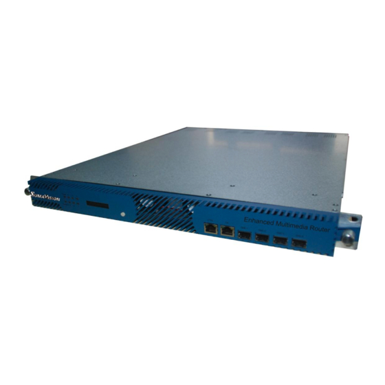
Product name: Integrated Media Processing Platform Model: EMR3.0, as shown in Fig. 2-1 EMR Front Panel. Manufacturer: Sumavision Technologies Co., Ltd., as shown in Fig. 2-1 EMR Front Panel. Identification description: there’s the ex-factory identification on the rear panel of the device, as shown in Fig. -
Page 14: Indicator
2.2.1 Indicator There are 8 indicators on EMR front panel, including: Power Run/Alarm Operating indicators (1-6) Connect to the power supply and turn on the power switch, the indicator of Power keep lighting. When the device starts and operates normally, there is no abnormality, the indicator of Run/Alarm on the device panel will turn green. -
Page 15: Lcd
The operating indicator of slot 2, 3, 4, 5 and 6 has the same status of indicator 1. Here no repeated description will be made. Since the gigabit master card is not equipped with the independently alarm light, if lights 1-6 are all green but the Run/Alarm light is red, it is possible that the gigabit master card is abnormal, the rotational speed of the fan is abnormal or the voltage of the power module is abnormal. -
Page 16: Connector Of The Device
2.2.4 Connector of the Device SUMAVISION EMR rear panel adopts the form of sub-panels. 6 slots formed with 6 sub-panels can be handled independently, which can facilitate the plugging and un-plugging of sub-cards. Ground terminal, power switch are placed on the rear panel, see Fig. - Page 17 Fig. 2-4 Appearance of SUMAVISION EMR Rear Panel ======================================= User can select to read relevant part of the Instructions according to the Platform settings purchased. The board card does not support the hot plugging. ======================================= 2.2.4.1 Power socket EMR provides two power sockets on the rear panel. The device will be powered on if the power lead is insert the power socket correctly.
-
Page 18: Chapter 3 Safety Precautions
If there’s any question during the transport, maintenance and operation of the device, please contact the Aftersales Technical Support Department of Sumavision, with the way to contact refering to the foregoing contents. The device is high-grade electronic product, and should be handled gently and kept away from falling or collision. - Page 19 and the distance between the cabinet side and the wall should be not less than 0.8m. Site room floor: Site room floor should be non-conductive, dust-proof, and its surface smoothness error should be less than 2mm per square meter. The volume resistivity of anti-static material should range from 1×10⁷Ω...
-
Page 20: Heat Emission Descriptions
The devices, air-conditioning system and lighting system should have their own power system respectively. 3.3.3 Heat Emission Descriptions There are two exhaust fans installed inside the EMR to lower the risen temperature caused by the working chips during the operation of the device. EMR exhaust flow is shown as Fig. -
Page 21: Power Supply Requirement
3.3.4 Power supply requirement Parameters for normal operation of EMR are shown as follows: Power supply: Voltage: 100V-240V AC; Power frequency: 50Hz-60Hz Power consumption: < 200W (Actual power associated with the device configuration) Nominal fuse: Grounding: the device should be well grounded through the ground ... -
Page 22: Chapter 4 Installation And Debugging
Please check whether the package of the device is damaged or not when receiving the device; in case of device’s damage, please contact the carrier company or the After-sales Technical Support Department of Sumavision in a timely manner. If you complete the installation and debugging of the device by yourself, please pay attention to the deformation of device and abnormal sound inside the device when unpacking the device;... -
Page 23: Debugging
Fig. 4-1 Assembly cabinet for EMR ====================================== The device can be installed in any plug-in frame of the assembly cabinet. However, the general principle for arranging the location of the device is that the connection between various stand-alone devices should be arranged neatly on the assembly cabinet in accordance with the flow of signal. -
Page 24: Methods For Debugging And Testing
4.5 Methods for Debugging and Testing EMR provides the function of Device IP address search through LCD display. The button can be used to light the LCD normally to facilitate the use by users. «ТВБизнес» - официальный дистрибьютор +7-812-600-25-77 TVBS.RU... -
Page 25: Chapter 5 Operating Methods
Chapter 5 Operating Methods This chapter mainly introduces the methods for system setting and use of EMR, which may be helpful for users to know initial knowledge about the system setting and operation steps of EMR. The system setting includes device IP, user management, factory reset and restart;... - Page 26 QAM modulation output, ASI multiplexing and routing, IP multiplexing and routing, TS and IP signal scrambling, etc. To complete the configuration of device successfully, we”ll describe basic operating processes of EMR through three parts: input section, multiplexing section and output interface section. EMR functions can be divided into three parts: Part one is about the input section.
- Page 27 4-Ch.DVB-S2 Demod card for configuration method) to support RF input; Analog video and audio input: EMR is configured with the MPEG2 SD AENC Card (see MPEG2 SD AENC Card for configuration method) or Analog SD ENC Card (see Analog SD ENC Card for configuration method) to support input and encoding of analog video and audio;...
- Page 28 Step 4: Select an output board card for multiplexing; Step 5: Click a destination output port for multiplexing; Step 6: Click Multiplex button; Step 7: Click “Apply” to validate the Multiplexing relation. ======================================= EMR device supports automatic searching. The user may manually refresh the input list by clicking the right button on the input port or card to choose the corresponding menu;...
-
Page 29: System Setting
PSI/SI node to the output port. The port multiplex deletion is only a shortcut operation on the page. In fact, it is equivalent to that the user has repeated to delete the program multiplex and the EMM multiplex. The port multiplex deletion does not cause the deletion for non-appointed PID below the output port. - Page 30 Fig. 5-3 WEB Management Network Configuration Table 5-1 Network Parameter Parameter Range Default Unicast IP not including 192.168.1.100 IP Address 127.XXX.XXX.XXX In accordance with the subnet 255.255.255 Subnet Mask mask standard In the same network with IP Address 192.168.1.1 Gateway Disable/Enable Disable DHCP...
- Page 31 Clock: set the system time of the device or the time synchronization server to enable the device to automatically synchronize the system time by the synchronization interval. Click “Apply” to complete the setting, as shown in Fig. 5-4 WEB Management Clock Configuration; Fig.
- Page 32 TDT/TOT: set the TDT/TOT form information of output of the gigabit master card. Click “Apply” to complete the setting, as shown in Fig. 5-5 WEB Management TDT/TOT Configuration; Fig. 5-5 TDT/TOT WEB Management Configuration TDT/TOT Table 5-3 Parameter Parameter Range Default Off/On...
- Page 33 PSI/SI: this page is used for setting the EMR searching mode and the searching distance between tables. Click “Apply” to complete the setting, as shown in Fig. 5-6 WEB Management PSI/SI Configuration. Fig. 5-6 PSI/SI WEB Management Configuration PSI/SI Table 5-4 Parameter Parameter...
- Page 34 Alarm: this page is used for inquiring EMR and warning information of each daughter card. It can set the warning IP, warning interval, language and the backup module warning switch. Click “Apply” to complete the setting, as shown in Fig. 5-7 WEB Management Alarm Configuration. Fig.
- Page 35 Log: this page is used for inquiring EMR and warning information of each daughter card. It can sieve and display the log according to the condition. Click “Refresh” to inquire, as shown in Fig. 5-8 WEB Management Log page. Fig.
- Page 36 License: this page is used for inquiring the EMR authorization status and setting the authorization code to change license status, Click “Apply” to complete the setting, as shown in Fig. 5-9 WEB Management License Configuration. Fig. 5-9 WEB Management License Configuration Table 5-6 License Parameter Parameter Range...
- Page 37 Version: click “Version” in “General” List to navigate to the page to inquire the version information of EMR and various daughter cards. Click “Refresh” to inquire, as shown in Fig. 5-10 WEB Management Version Information. Fig. 5-10 WEB Management Version Information «ТВБизнес»...
- Page 38 Fig. 5-11 WEB Management Misc Configuration. Fig. 5-11 WEB Management Misc Configuration Table 5-7 Misc Parameter Parameter Range Default 0~31 character long EMR3.0 Device Name Decimal/Hexadecimal Hexadecimal Service ID Format Decimal/Hexadecimal Hexadecimal PID Format...
- Page 39 Permission: add or delete three kinds of users, including “Administrator”, “Power user” and “User”, as shown in Fig. 5-12 WEB Management Permission Configuration. Fig. 5-12 WEB Management Permission Configuration «ТВБизнес» - официальный дистрибьютор +7-812-600-25-77 TVBS.RU...
-
Page 40: Snmp Network Management
5.2 SNMP Network Management The EMR background software is embedded into the network management software eManager of Beijing Sumavision Technologies Co. Ltd., which uses the same SNMP communication protocol with the network management software. As a result, the user can manage the EMR when installing the network management software. -
Page 41: Operating Method
The initial password is Administrator and the password is “sumavision”. Fill in the server and the IP address. Click “OK” to start the SNMP network management, as shown in Fig. 5-15 Login Interface for SNMP Network management. - Page 42 configuration method) or ASI 5InOut Card (see ASI 5InOut Card for configuration method) to support ASI input; DS3/E3 input: EMR is configured with DS3 In4 Card (see DS3 In4 Card for configuration method) or DS3 adapter (see DS3 adapter for configuration method) to support DS3/E3 stream input;...
-
Page 43: System Configuration
SD-ADEC Card for configuration method) to support the decoded video and audio output. 5.2.2 System configuration When the SNMP network management is started, it needs to add the equipment at first and refresh the hardware at first and then the EMR can be managed. The steps are as follows: Step 1: follow the following operation steps when the user requires adding the equipment:... - Page 44 Fig. 5-16 Add Equipment Step 2: Open the SNMP configuration window of equipment Fig. 5-17 Choose of SNMP Configuration Menu «ТВБизнес» - официальный дистрибьютор +7-812-600-25-77 TVBS.RU...
-
Page 45: Board Card Description
Right click after choosing the equipment in the equipment management window and choose “SNMP config” in the pop-up right click menu to pop up the equipment parameter configuration interface. Step 3: refresh equipment parameter. Click “Refresh Dev” to refresh the board card structure information of the current equipment. -
Page 46: Main Gbe Card
5.3.1 Main GbE Card 5.3.1.1 Interface The main GbE card is provided by the EMR itself and is different from other board cards because the Main GbE Card occupies any card slot but is integrated with the EMR. The interface card has four Ethernet ports, from left to right, they are Gigabit input/output port 1, Gigabit input/output port 2, Gigabit input/output port 3 and Gigabit input/output port 4. - Page 47 Input backup: used for setting the backup switch of Ethernet port 1 and 2 with the input backup function, the backup mode and the switch condition; Output backup: used for setting the backup switch of Ethernet port 1 and 2 with ...
- Page 48 5.3.1.2.2 Receiving Settings Fig. 5-21 Main GbE Card Receiving Settings Step 1: Click “GbE n” of “Cards” of WEB network management to navigate to GbE n parameter settings page; Step 2: Click “Receive” to navigate to receiving parameter settings page; Step 3: Click “Add”...
- Page 49 Fig. 5-22 Main GbE Card Receiving Monitor Step 7: When the receiving parameter is configured and the network is connected, click “Main GbE card” in the “Cards” to switch to the information page of the Main GbE card to click “Receive” in the top of the page to check input information of each port. Port deletion function: When it requires deleting some ports, it can choose the check box in front of the port and click the “delete”...
- Page 50 Fig. 5-23 Main GbE Card Receiving Reference Settings ======================================= A network interface of the Main GbE Card supports up to 256 receiving ports; When the gigabit network transmission protocol is RTP, please set even numbers of receiving ports; When the gigabit receiving adopts V3 version of IGMP protocol, “receiving mode and source IP1 and IP2 are available”, or the default settings shall prevail.
- Page 51 5.3.1.2.3 Transmitting settings Fig. 5-24 Main GbE Card Sending Settings Step 1: Click “GbE n” of “Cards” of WEB network management to navigate to GbE n parameter settings page; Step 2: Click “Transmit” to navigate to sending parameter settings page; Step 3: Click “Add”...
- Page 52 Fig. 5-25 Main GbE Card Transmit Monitor Step 7: When Multiplexing of the output programme is finished and the network is connected, click “Main GbE card” in the “Cards” to switch to the information page of the Main GbE card to click “Transmit” in the top of the page to check output information of each port.
- Page 53 After setting the input port, click Multiplex button in the “Multiplexing” in the top of the page to choose the Main GbE card as the output card, and choose the multiplexing of the input card for the output port corresponding to the Main GbE card according to the frequency point planning, and then click “Apply”.
- Page 54 corresponding MAC address. The equipment can directly use corresponding MAC address rather than sending APR REQUEST to obtain the target MAC when the target IP address is given. Step 1: click WEB network management “GbE n” to log in the Ethernet port setting page;...
- Page 55 network interface 2. Input Ethernet port backup: Function description: for the four Ethernet ports with the Main GbE Cards, the Ethernet ports 1 and 3 are the backup of a 1+1 group and the Ethernet ports 2 and 4 are the backup of another 1+1 group.
- Page 56 1 and 3, while the group 2 refers to the main and standby backup of the Ethernet ports 2 and 4. Step 4: click the backup mode option on the page to choose the mode complying with the real application requirement. It can choose the “Main Priority”, “Floating”, “One-Way Switch”, “Assign Main”...
- Page 57 and backup Ethernet ports output. The bearing content must be the same. When the backward equipment uses the received backup, two identical program sources are available. Fig. 5-29 Main GbE Card Output Ethernet port backup Step 1: click WEB net manager “Main GbE Card” to log in the board card page; Step 2: click “Output Backup”...
- Page 58 limited to the two Ethernet ports of the same equipment. It also includes the backup between the Ethernet ports of different devices. ======================================= One Ethernet port can be provided with 8 groups. The group working mode using the backup in the same Ethernet port must be identical, being the master equipment or the backup equipment.
- Page 59 Fig. 5-30 Main GbE Card Output port Backup Step 1: click WEB net manager “GbE n” to log in the Ethernet port page; Step 2: click “Backup” to log in the output port backup setting page; Step 3: click the work mode on the page option to select the “Main Device” or “Backup Device”...
- Page 60 Step 5: fill the “Backup IP Address” and the “Backup UDP Port” on the page. Fill IP addresses of corresponding matched ports in the backup IP address bar of the master and backup equipment (the master equipment fills the IP address of the backup equipment in the backup IP address, while the backup equipment fills the IP of corresponding master equipment).
- Page 61 between ports. When the code rate is beyond the threshold value, the route is deemed as abnormal and the switch shall be made. Step 11: click the “Apply” on the page to put the backup setting into effect. After setting the backup for output port of the master equipment, it shall log in the backup equipment net manager to set the backup parameter for output port of the backup equipment, backup group number for output port of backup equipment, the minimum code rate threshold and the maximum code rate threshold.
- Page 62 Table 5-9 Main GbE Card Transmitting Parameter Parameter Range Default length of name 0~31 Udp Port n Name 1~256 Add Port Number Destination IP unicast IP or multicast IP 192.165.52.100 Address IP Address Step 0~255 Value Destination UDP 1~65535 1234 Port UDP Port Step 0~65534...
-
Page 63: Input Asi Card
Table 5-12 Main GbE Card General Parameter Parameter Range Default Net IP unicast IP not include 127.XXX.XXX.XXX 192.168.1.136 Address Legal Subnet Mask Address 255.255.255.0 Subnet Mask unicast IP not include 127.XXX.XXX.XXX,must the same 192.168.1.36 Gateway subnet with Net IP Address Auto-Negotiation/1Gbps AN/SGMII 1Gbps Full/1Gbps Speed and Auto-Negotiation... -
Page 64: Output Asi Card
page. Fig. 5-33 5 Input ASI Card 5.3.2.3 Parameter Table 5-14 5 Input ASI Card Parameter Parameter Range Default 0x0~0x1fff 0x1fff Appointed PID On/Off Alarm 5.3.3 4 Output ASI Card 5.3.3.1 Interface 4 output ASI card provides 4 output interface of 75ΩBNC for ASI output, 1 Ethernet interface for connecting and communicating CAS, as shown in Fig. - Page 65 Multiplex in Section 5.1.1.2Multiplexing Setting, the appropriate system code rate can be set in corresponding port and the normal output can be made then. The 4 output ASI card can realize the scrambling action for the program outputted by four ASI output routes via the scrambling Ethernet port of the back board and the board card.
-
Page 66: Asi 5Inout Card
Table 5-15 4 Output ASI Card Parameter Parameter Range Default 0~213000000 Total Bitrate(bps) 188 Byte/204 Byte 188 Byte Packet Format On/Off Re-generate PCR On/Off Alarm 32-8191 8191 PCR_PID 5.3.4 ASI 5InOut Card 5.3.4.1 Interface ASI 5InOut Card provides 5 75ΩBNC ports, which are flexible for the ASI signal input/output, as shown in Fig. - Page 67 Fig. 5-37 ASI 5InOut Card Step 1: Click “ASI 5InOut Card” of “Cards” of WEB network management to navigate to card settings page; Step 2: Click “Card Type” to choose “ASI 5InOut Card”; Step 3: Customize each port as “Input” or “Output” according to the demand; Step 4: Click “Apply”...
- Page 68 Fig. 5-38 ASI 5InOut Card Input Settings Step 5: Click “Input Port n” of WEB network management to navigate to input port page; Step 6: Click “Config” to navigate to setting page; Step 7: Set the “Appointed PID” and “Alarm” switch of the input port; Step 8: Click “Apply”...
- Page 69 Fig. 5-39 ASI 5InOut Card Output Settings Step 9: Click “Output Port n” of WEB network management to navigate to Output port page; Step 10: Click “Config” to navigate to setting page; Step 11: Set the “Total Bitrate”, “Packet Format”, “Alarm” switch and the “Re-generated PCR”...
- Page 70 Fig. 5-40 ASI 5InOut Card Concentrator Step 1: Click “ASI 5InOut Card” of “Cards” of WEB network management to navigate to card settings page; Step 2: Click “Card Type” to choose “Concentrator”; Step 3: Click “Apply” to validate the parameter; «ТВБизнес»...
- Page 71 Fig. 5-41 ASI 5InOut Card Concentrator Input Settings Step 4: Click “Input Port n” of WEB network management to navigate to input port page; Step 5: Click “Config” to navigate to setting page; Step 6: Set the “Input” switch and “Alarm” switch of the input port according to the demand;...
- Page 72 Fig. 5-42 ASI 5InOut Card Deconcentrator Step 1: Click “ASI 5InOut Card” of “Cards” of WEB network management to navigate to card settings page; Step 2: Click “Card Type” to choose “Deconcentrator”; Step 3: Click “Apply” to validate the parameter; «ТВБизнес»...
- Page 73 Fig. 5-43 ASI 5InOut Card Deconcentrator Input Settings Step 4: Click “Input Port” of WEB network management to navigate to input port page; Step 5: Click “Config” to navigate to setting page; Step 6: Choose “Current Card” or “Others” as the input source. When “Others” is chosen, you may navigate to the transparent flow transmission of “Output”...
- Page 74 Fig. 5-44 ASI 5InOut Card Deconcentrator Output Settings Step 8: Click “Output Port n” of WEB network management to navigate to Output port page; Step 9: choose the output signal and output packet size of the 4-channel output of the Deconcentrator according to the actual situation;...
-
Page 75: Ds3 Adapter Card
Table 5-16 ASI 5InOut Card Parameter Parameter Range Default On/Off Alarm ASI5InOut Card/ Concentrator/ Concentrator Card Type Deconcentrator/ SMPTE 310 Appointed 0~8191 Input On/Off Alarm Total 0~213000000 Bitrate(bps) Packet 188 Byte/204 Byte 188 Byte Format Re-generate Output On/Off Adjust PCR On/Off Structure On/Off... - Page 76 Fig. 5-45 DS3 adapter Card 5.3.5.2 Function DS3 adapter Card provides 5 BNC ports, which are ASI_OUT, ASI_IN, DS3_OUT1, DS3_OUT2 and DS3_IN from left to right. DS3 adapter supports two-way adapted output of ASI and DS3. 5.3.5.2.1 Input setting ASI input setting When the ASI input is used, the input source shall be connected for the DS3 adapter Card ASI-IN.
- Page 77 Step 4: click the “Apply” on the page after setting the parameter to put the setting parameter into effect. The monitoring interface shall display the code rate information of the current receiving ASI input source. Fig. 5-47 DS3 Adapter Card ASI Input Monitor «ТВБизнес»...
- Page 78 DS3 input setting When the DS3 input is used, the DS3 input source shall be connected for the DS3 adapter Card DS3-IN. Fig. 5-48 DS3 adapter Card DS3 Input Parameter Setting Step 1: click the “DS3 In” in the “DS3 adapter Card” of Web network management to log in the DS3 input port to set the page;...
- Page 79 port to realize the normal output. Switch on “Loop” function: the input port and the output port of the DS3 adapter card cannot be used for conducting the corresponding adaptation output rather than the multiplex operation. Namely, the input stream of the DS3 input port can be directly adapted to the output of the ASI output port, while the input stream of the ASI input port can be directly adapted to the output of the DS3 output port and the program is unable to be modified via the multiplex.
- Page 80 5.3.5.2.2 Output setting ASI output setting Fig. 5-50 DS3 adapter Card ASI Output Parameter Setting Step 1: click the “ASI Out” in the “DS3 adapter Card” of Web network management to log in the ASI output port to set the page; Step 2: set the “Total Bitrate”...
- Page 81 DS3 output setting Fig. 5-51 DS3 adapter Card DS3 Output Parameter Setting Step 1: click the “DS3 Out” in the “DS3 adapter Card” of Web network management to log in the DS3 output port to set the page; Step 2: set the DS3 output parameter according to the demand of the real application, select the “Frame Format”, “Output Bit Sequence”, “RS Coding”, “Interleaved Coding”, “Scramble”...
-
Page 82: Ds3 In4 Card
Table 5-18 DS3 Adapter Card DS3 Parameter Parameter Range Default On/Off Input On/Off Loop DS3/E3 Switch DS3 Mode/E3 Mode DS3 Mode Mode Normal Mode/Tandberg/NP Normal Mode Multi Protocol Mode No Frame/ C-bit/ M13 Frame Format Input Input Bit MSB/LSB Sequence On/Off RS Decoding Interleaved... -
Page 83: 6-Ch.qam Card
Fig. 5-53 DS3 In4 Card 5.3.6.3 Parameter Table 5-19 DS3 In4 Card Parameter Parameter Range Default On/Off Input DS3 Mode/E3 Mode DS3 Mode DS3/E3 Switch Mode MSB/LSB Input Bit Sequence Normal Mode/TB6010 Normal Mode Adaptation Protocol No Frame/C-bit/M13 No Frame Frame Format On/Off RS Decoding... - Page 84 Fig. 5-54 6-Ch.QAM Card 5.3.7.2 Function 6-Ch.QAM Card contains a RF output port supporting 8-adjacent frequency output. It can multiplex the program of other input ports to this port and output the program from this port. For the program multiplex method, refer to section 5.1.1.2Multiplexing Setting. Set the QAM parameter until the real demand is satisfied.
-
Page 85: Dvb-T/H-4 Mod. Card
Fig. 5-56 6-Ch.QAM Card Port Parameter Config 5.3.7.3 Parameter Table 5-20 6-Ch.QAM Card Parameter Parameter Range Default On/Off Alarm 3.0 Scramble Module/ Scramble Card Select Scrambler Scramble Card ANNEX_A/ ANNEX_B ANNEX_A Channel Coding 6MHz/8MHz 8MHz Channel BW On/Off Spectrum Inversion On/Off 95~115 Output Level(dBuV) - Page 86 DVB-T/H-4 Mod. Card: Fig. 5-57 DVB-T/H-4 Mod. Card 5.3.8.2 Function The DVB-T/H-4 Mod. Card is provided with an RF output interface used for modulating output of 8 TS stream routes with four frequency points in stages. It can multiplex the program of other input ports to this port and output the program from this port. For the program multiplex method, refer to section 5.1.1.2Multiplexing Setting.
- Page 87 Level” according to the information of signal frequency point; Step 5: Set the “Alarm” switch of the card to turn on or off the switch; Step 6: After setting the parameter, click “Apply” to validate the parameter; The monitoring interface shall display the status of the current output stream, etc.
- Page 88 Fig. 5-60 DVB-T/H-4 Mod. Card RF Out Config Basic Parameter Setting Step 7: Click “RF Out” of “DVB-T/H-4 Mod. Card” of WEB network management to navigate to port settings page; Step 8: Click “Config” to navigate to setting page; Step 9: Click “Basic” to navigate to Basic parameter setting page; Step 10: Open the “Switch”...
- Page 89 Fig. 5-61 DVB-T/H-4 Mod. Card RF Out Config Advanced Parameter Setting Step 14: click the “Advanced” on the page to log in the senior parameter setting page; Step 15: set the senior function according to the demand, select the DVB-H signaling of port, cellular identification enable action, cellular identification, T.S.
- Page 90 Fig. 5-62 DVB-T/H-4 Mod. Card RF Out Monitor 5.3.8.3 Parameter Table 5-21 DVB-T/H-4 Mod. Card Parameter Parameter Range Default On/Off Alarm On/Off 5MHz/6MHz/7MHz/8MHz 5MHz Output BandWidth On/Off Spectrum Inversion 90~120 Output Level (dBuV) «ТВБизнес» - официальный дистрибьютор +7-812-600-25-77 TVBS.RU...
-
Page 91: Dvb-S/S2 Mod. Card
Fig. 5-63 DVB-S/S2 Mod. Card 5.3.9.2 Function DVB-S/S2 Mod. Card bases on EMR3.0 platform to support 1-channel ASI input (no Multiplexing) and 1-channel RF modulated output. Its functions include: when “Backboard Muxing TS” is chosen, it may choose the input stream of other cards for modulated output and when “Local ASI TS”... - Page 92 Fig. 5-64 DVB-S/S2 Mod. Card 5.3.9.3 Parameter Table 5-23 DVB-S/S2 Mod. Card Parameter Parameter Range Default ON/OFF Alarm Switch Backboard Muxing TS/Local ASI Backboard Muxing TS Input Source DVB-S/DVB-S2 DVB-S Modulation Standard (QPSK-1/2)/ (QPSK-2/3)/ FEC Rate & (QPSK-3/4)/ (QPSK-5/6)/ QPSK-1/2. Constellation (QPSK-7/8) Normal/Short...
-
Page 93: Mpeg2 Sd Aenc Card
5.3.10 MPEG2 SD AENC Card 5.3.10.1 Interface MPEG2 SD AENC Card provides the video input interface of 75ΩBNC, and provides audio input interface as the phoenix printed circuit board terminals of MINI COMBICON (MC) socket and plug, plug direction parallel with conductors axial. MPEG2 SD AENC Card is shown in Fig. - Page 94 5.3.10.3 Parameter Table 5-24 MPEG2 SD AENC Card Parameter Type Parameter Range Default On/Off Switch Color bar/No Output Color bar No Source Control PAL/NTSC/AUTO/PAL-M/PAL-N/SECAM Format 0-255 Video Level 0-255 Chroma Phase 0-255 Black Level 0-255 Chroma Gain Video 1500000-15000000 4200000 Bitrate (bps) CBR/VBR Bitrate Mode...
-
Page 95: Mpeg2 Sd Denc Card
32-8190 Slot releted PMT PID 32-8190 Slot releted Video PID 32-8190 Slot releted MP2 PID 32-8190 Slot releted AC3 PID 32-8190 Slot releted DRA PID On/Off On/Off CC Even Field On/Off CC Odd Field On/Off Line10-Line22 Line 21 Even Field Line Line10-Line22 Line 21 Odd Field Line... - Page 96 Fig. 5-68 MPEG2 SD DENC Card 5.3.11.3 Parameter Table 5-25 MPEG2 SD DENC Card Parameter Type Parameter Range Default On/Off Switch PAL/NTSC/AUTO/PAL-M/PAL-N/SECAM Format CBR/VBR Bitrate Mode 1500000-15000000 4200000 Bitrate (bps) 1300000-14800000 3800000 VBR (bps) Video III/IPP/IBP/IBBP IBBP GOP Structure 4-30 Gop Size 4:3/16:9 Aspect Ratio...
- Page 97 64Kbps/96Kbps/112 Kbps/ 128Kbps/ 160Kbps/192 Kbps/224 Kbps/256 Kbps/ 256Kbps MP2 Bitrate 320 Kbps/384Kbps 48kHz/44.1kHz/32kHz 48kHz MP2 Sample Rate On/Off AC3 Coding 2/0 / 1/0 AC3 Mode -20db-20db AC3 Volume Digital/Embeded Embeded AC3 Input 56Kbps/64Kbps/80Kbps/96Kbps/ 112 Kbps/ 128Kbps/ 160Kbps/ Audio 192 Kbps/224 Kbps/256 Kbps/ 192Kbps AC3 Bitrate 320 Kbps/384Kbps/448Kbps/...
-
Page 98: Analog Sd Enc Card
5.3.12 Analog SD ENC Card 5.3.12.1 Interface Analog SD ENC Card provides the video input interface of 75ΩBNC, and provides audio input interface as the phoenix printed circuit board terminals of MINI COMBICON (MC) socket and plug, plug direction parallel with conductors axial. Analog SD ENC Card is shown in Fig. - Page 99 5.3.12.3 Parameter Table 5-26 Analog SD ENC Card Parameter Type Parameter Range Default On/Off On/Off 300000~60000000 4000000 Bitrate(bps) SDI/Color Bar/Black Page Selection MPEG-2 MPEG-2 Encoding Type Output Auto Auto Resolution Main Main Profile Main Main Level Auto/4:3/16:9 Auto Aspect Ratio Rate Control Video Scene Change...
-
Page 100: Digital Enc Card
5.3.13 Digital ENC Card 5.3.13.1 Interface The digital video input port and the audio input port of the Digital ENC Card are 75ΩBNC port, as shown in Fig. 5-71 Digital ENC Card: Fig. 5-71 Digital ENC Card 5.3.13.2 Function Digital ENC Card may code 2-channel digital signal to code the input digital video and analog audio to TS. -
Page 101: Sd-Adec Card
Table 5-27 Digital ENC Card Parameter Type Parameter Range Default On/Off On/Off 300000~60000000 4000000 Bitrate(bps) SDI/Color Bar/Black Page Selection MPEG-2 MPEG-2 Encoding Type Output Auto Auto Resolution Main Main Profile Main Main Level Auto/4:3/16:9 Auto Video Aspect Ratio Rate Control Scene Change Off/On Detection... - Page 102 socket and plug, plug direction parallel with conductors axial. SD-ADEC Card is shown in Fig. 5-73 SD-ADEC Card: Fig. 5-73 SD-ADEC Card 5.3.14.2 Function The SD-ADEC Card can be used for decoding the SD program, support the output of two video routes and two audio routes and decoding and outputting the TS stream to the television set or monitor.
- Page 103 ======================================= The audio decoding type supported by the SD-ADEC Card requires corresponding authorization support. It can be realized by purchasing the authorization. The authorization status is divided into “EAC3, HEAAC”, “HEAAC” or “AC3”, which support “All Audio Types”, “AAC Audio” or “Dolby Audio”, respectively. =======================================...
- Page 104 “Custom” decoding is selected, it needs to set corresponding “PCR PID”, “Video PID”, “Audio PID” and “Teletext PID” to realize the user-defined decoding; Step 5: set “Video Decoding”, “Audio Decoding” and corresponding “VBI” parameter according to the demand of real application. Step 6: click the “Apply”...
-
Page 105: Descramble Card
Table 5-28 SD-ADEC Card Parameter Type Parameter Range Default On/Off Decode Freeze/Black/Colorbar/No Output Black Error Handle General PCR Master/Video Master/Audio PCR Master Sync Mode Master Custom/Set Program Set Program Service 0~8191 8191 PCR PID Service 0~8191 8191 Video PID Decoding 0~8191 8191 Audio PID... - Page 106 5.3.15.2.1 CAM descrambling setting When the CA scrambling program is found in the received program, it can set the descrambling information in the “CAM Setting” page. After the de-scrambling, the clear-stream program is the multiplex output. For the program multiplex method, refer to section 5.1.1.2Multiplexing Setting.
- Page 107 Fig. 5-79 Descramble Card CAM Descrambling Step 5: click the “CAM Descramble” on the “Descramble Card” of WEB network management; Step 6: choose the de-scrambling CAM card for each program; Step 7: click the “Apply” on the page after setting the parameter to put the setting parameter into effect.
- Page 108 Fig. 5-80 Descramble Card BISS Setting Step 1: click WEB network management “Descramble Card” to log in the board card setting page; Step 2: click the “BISS” on the page to log in the BISS de-scrambling setting page; Step 3: choose “On” on the “BISS Descramble” Switch; Step 4: set the de-scrambling secrete key information, choose “Biss mode”, set the secrete “Key”, choose and set the “ID”;...
-
Page 109: Dvb-S2 Desc Card
Table 5-29 Descramble Card CAM Descrambling Parameter Parameter Range Default On/Off CAM Descramble Switch 7M/9M/12M/15M CAM CLK On/Off CAM A Alarm On/Off CAM B Alarm 0~255 CAM A CAPMT Interval(ms) 0~255 CAM B CAPMT Interval(ms) No Descramble/CAM No Descramble A/CAM B Table 5-30 Descramble Card BISS Descrambling Parameter Parameter Range... - Page 110 5.3.16.2.1 Receiving Parameter Fig. 5-82 DVB-S2 Desc Card Receiving Parameter Config Step 1: Click “Port 1” of “DVB-S2 Desc Card” of WEB network management to navigate to port page; Step 2: Click “Config” to navigate to setting page; Step 3:Set the “Tuner” as “On” and choose the “Standard”, “Polarize” and “22Khz” according to the satellite programme to be received, and fill in the “Down Frequency”, “Local Frequency”...
- Page 111 Fig. 5-83 DVB-S2 Desc Card Receiving Parameter Monitor 5.3.16.2.2 CAM Descrambling Settings When the CA scrambling program is found in the received program, it can set the descrambling information in the “CAM Config” page. After the de-scrambling, the unscrambling stream programme will output in the output port. For the program multiplex method, refer to section 5.1.1.2Multiplexing Setting.
- Page 112 Fig. 5-84 DVB-S2 Desc Card CAM Descrambling Settings Step 1: Click “DVB-S2 Desc Card” of WEB network management to navigate to the board card page; Step 2: Click “CAM Config” to navigate to CAM setting page; Step 3: Choose “On” in “CAM Descramble Switch”, choose “CAM CLK” according to the need and choose “On”...
- Page 113 Fig. 5-85 DVB-S2 Desc Card CAM Information Fig. 5-86 DVB-S2 Desc Card CAM Descramble «ТВБизнес» - официальный дистрибьютор +7-812-600-25-77 TVBS.RU...
- Page 114 Step 5: Click “CAM Descramble” in the “DVB-S2 Desc Card” of WEB network management; Step 6: Choose the CAM card for the descrambling of each programme; Step 7: After setting the parameter, click “Apply” in the page to validate the parameter. The page will display the descrambling status of the programme.
- Page 115 5.3.16.3 Parameter Table 5-31 DVB-S2 Desc Card Receiving Parameter Parameter Range Default On/Off Tuner DVB-S/DVB-S2 DVB-S Standard Stop/Start Stop Search Right/Left/Off Polarize On/Off 22KHz 1~99999 Downlink (the difference of downlink Freq and Local 4080 Frequency(MHz) Freq must be between 950~2150) 1~99999 Local (the difference of downlink Freq and Local...
-
Page 116: Abs-S Demod Card
5.3.17 ABS-S Demod Card 5.3.17.1 Interface The ABS-S Demod Card is based on the EMR3.0 platform to provide two CAM card slots to the single route RF input for receiving and de-scrambling RF signal of direct broadcast satellite, as shown in Fig. 5-88 ABS-S Demod Card. - Page 117 Step 2: Click “Config” to navigate to setting page; Step 3: Set the “Tuner” as “On” and choose the “Standard”, “Polarize” and “22Khz” according to the satellite programme to be received, and fill in the “Down Frequency”, “Local Frequency” and “Symbol Rate”; Step 4: After setting the parameter, click “Apply”...
- Page 118 When the CAM card is inserted on the board card, the CAM information page will show the CAS_ID of corresponding card. Fig. 5-91 ABS-S Demod Card CAM Descramble Step 5: Click “CAM Descramble” in the “ABS-S Demod Card” of WEB network management;...
-
Page 119: Dvb-C Demod Card
Table 5-35 ABS-S Demod Card CAM Descrambling Parameter Parameter Range Default On/Off CAM Descramble Switch 7M/9M/12M/15M CAM CLK On/Off CAM A Alarm On/Off CAM B Alarm 0~255 CAM A CAPMT Interval(ms) 0~255 CAM B CAPMT Interval(ms) No Descramble/CAM No Descramble A/CAM B 5.3.18 DVB-C Demod Card 5.3.18.1 Interface... - Page 120 5.3.18.2.1 Receiving Parameter Fig. 5-93 DVB-C Demod Card Receiving Parameter Step 1: Click “Port 1” of “DVB-C Demod Card” of WEB network management to navigate to port page; Step 2: Click “Config” to navigate to setting page; Step 3: Set “Demod” Switch as “On”; Step 4: Choose the “Modulation Mode”...
- Page 121 Fig. 5-94 DVB-C Demod Card CAM Setting 5.3.18.2.2 CAM Descrambling Settings When the CA scrambling program is found in the received program, it can set the descrambling information in the “CAM Config” page. After the de-scrambling, the unscrambling stream programme will output in the output port. For the program multiplex method, refer to section 5.1.1.2Multiplexing Setting.
- Page 122 Fig. 5-95 DVB-C Demod Card CAM Descrambling Setting Step 1: Click “DVB-C Demod Card” of WEB network management to navigate to the board card page; Step 2: Click “CAM Config” to navigate to CAM setting page; Step 3: Choose “On” in “CAM Descramble Switch”, choose “CAM CLK” according to the need and choose “On”...
- Page 123 Fig. 5-96 DVB-C Demod Card CAM Information Fig. 5-97 DVB-C Demod Card CAM Descramble «ТВБизнес» - официальный дистрибьютор +7-812-600-25-77 TVBS.RU...
-
Page 124: Dvb-S2 Demod Desc Card
Step 5: Click “CAM Descramble” in the “DVB-C Demod Card” of WEB network management; Step 6: Choose the CAM card for the descrambling of each programme; Step 7: After setting the parameter, click “Apply” in the page to validate the parameter. The page will display the descrambling status of the programme. - Page 125 5.3.19.2 Function 5.3.19.2.1 Receiving Parameter Fig. 5-99 DVB-S2 Demod Desc Card Receiving Parameter Config Step 1: Click “RF” of “DVB-S2 Demod Desc Card” of WEB network management to navigate to port page; Step 2: Click “Config” to navigate to setting page; Step 3:Set the “Tuner”...
- Page 126 Fig. 5-100 DVB-S2 Demod Desc Card Receiving Parameter Monitor 5.3.19.2.2 Selection of input source The input of this card and the multiplexing input are both the options for the input source of DVB-S2 Demod Desc Card. When the option of input from this card is selected, the input ports CAM-A, CAM-B and BISS of the multiplexing interface shall display the program list inputted from this card according to the selection of the input source.
- Page 127 program descrambling information in the “CAM-A” and “CAM-B” page. After the de-scrambling, the clear-stream program is the multiplex output. For the program multiplex method, refer to section 5.1.1.2Multiplexing Setting. Fig. 5-101 DVB-S2 Demod Desc Card CAM Descrambling System Parameter Setting Step 1: click “CAM-A”...
- Page 128 Fig. 5-102 DVB-S2 Demod Desc Card CAM Descrambling Program Setting Step 5: click the “Program” in the “DVB-S2 Demod Desc Card” CAM setting page of the WEB network management to log in the program setting page; Step 6: decide whether to adopt the de-scrambling action for each program; Step 7: click the “Apply”...
- Page 129 Fig. 5-103 DVB-S2 Demod Desc Card CAM Descrambling Monitor 5.3.19.2.4 BISS Descrambling Setting When the BISS scrambling program is found in the received program, it can set the descrambling information in the “BISS” page. After the de-scrambling, the unscrambling stream programme will output in the output port. For the program multiplex method, refer to section 5.1.1.2Multiplexing Setting.
- Page 130 Fig. 5-104 DVB-S2 Demod Desc Card BISS Descrambling System Parameter Setting Step 1: click the “BISS” on the “DVB-S2 Demod Desc Card” page of WEB network management to log in the BISS de-scrambling setting page; Step 2: click the “System” on the page to log in the BISS descrambling system setting page;...
- Page 131 Fig. 5-105 DVB-S2 Demod Desc Card BISS Descrambling Key Setting Step 7 click the “Key” in the “DVB-S2 Demod Desc Card” BISS descrambling setting page of the WEB network management to log in the secrete key setting page; Step 8: click the “Add” on the page to pop up the BISS secrete key adding and modification page;...
- Page 132 Fig. 5-106 DVB-S2 Demod Desc Card BISS Descrambling Program Setting Step 11: click the “Program” in the “DVB-S2 Demod Desc Card” BISS de-scrambling setting page of the WEB network management to log in the program setting page; Step 12: click the “Show Detail” on the page to spread the program secrete key selection page.
- Page 133 Fig. 5-107 DVB-S2 Demod Desc Card BISS Descrambling Monitor 5.3.19.3 Parameter Table 5-38 DVB-S2 Demod Desc Card Receiving Parameter Parameter Range Default Off/On Tuner DVB-S/DVB-S2 DVB-S Standard Off/On TS Change Off/On 22KHz Vertical/Horizontal/Off Polarize Satellite 1 Satellite 1/…/ Satellite 16 DiSEqC Stop/Start Stop...
-
Page 134: 4-Ch.dvb-T2 Demod Card
Table 5-39 DVB-S2 Demod Desc Card CAM Descrambling Parameter Parameter Range Default Local Input/Multiplexing Input Multiplexing Input Source Off/On CAM Descramble 6/7/9/12/15/17/20/25/27 Clock (MHz) 0~255 CaPmt Interval (ms) 0~8191 8191 Appointed Input PID Appointed Output 0~8191 8191 Table 5-40 DVB-S2 Demod Desc Card BISS Descrambling Parameter Parameter Range Default... - Page 135 ======================================= The frequency point receiving quantity of the four-channel DVB-T2 demodulation and receiving card is decided by the authorization obtained. The authorization for four frequency points at most is supported. ======================================= Fig. 5-109 4-Ch.DVB-T2 Demod Card Parameter Set the “Alarm” switch of the card to turn on or off the switch. After setting the parameter, click “Apply”...
- Page 136 Fig. 5-110 4-Ch.DVB-T2 Demod Card Port Config Step 1: Click “Port n” of “4-Ch.DVB-T2 Demod Card” of WEB network management to navigate to port settings page; Step 2: Click “Config” to navigate to setting page; Step 3: Open the “Demod” switch; Step 4: Set the “Bandwidth”, “Standard”...
-
Page 137: 4-Ch.dvb-S2 Demod Card
Fig. 5-111 4-Ch.DVB-T2 Demod Card Port Monitor 5.3.20.3 Parameter Table 5-41 4-Ch.DVB-T2 Demod Card Parameter Parameter Range Default On/Off Alarm On/Off Demod Off/Type1/Type2 Ts change 8MHz/7MHz/6MHz/5MHz 8MHz Bandwidth DVB-C/DVB-T/DVB-T2 DVB-T2 Standard HP/LP Profile 0~255 PLP ID 42000~870000 554000 Center Frequency(KHz) 5.3.21 4-Ch.DVB-S2 Demod card 5.3.21.1 Interface 4-Ch.DVB-S2 Demod card... - Page 138 Fig. 5-112 4-Ch.DVB-S2 Demod card 5.3.21.2 Function 4-Ch.DVB-S2 Demod card provides 4 RF input ports for the reception of the RF signal of DVB-S/DVB-S2 standard. WEB network management may check the current status information and set the receiving parameter of the 4-Ch.DVB-S2 Demod card. The input program can be refreshed as per as the Setting Method for Multiplex in Section 5.1.1.2Multiplexing Setting and the output is multiplexed finally.
- Page 139 The monitoring interface shall display the code rate information which is currently received. Fig. 5-114 4-Ch.DVB-S2 Demod card Receiving Parameter Monitor 5.3.21.2.2 BISS Descrambling Settings When the BISS scrambling program is found in the received program, it can set the descrambling information in the “BISS”...
- Page 140 Fig. 5-115 4-Ch.DVB-S2 Demod card BISS Descrambling Settings Step 1: Click “Port n” of WEB network management to navigate to port page; Step 2: Click “BISS” to navigate to BISS setting page; Step 3: Choose “On” of the “BISS Descramble” switch Step 4: Set the descrambling key information, choose the “BISS Mode”, set the “Key”, and choose and set the “ID”;...
-
Page 141: Statmux4 Card
Table 5-42 4-Ch.DVB-S2 Demod card Receiving Parameter Parameter Range Default On/Off Tuner DVB-S/DVB-S2 DVB-S Standard On/Off TS Change On/Off 22KHz Vertical/Horizontal/Off Polarize Satellite 1~Satellite 4(Version1.0/2.0) Satellite Satellite 1~Satellite 16(Version1.1/2.1) DiSEqC 1(Version1.0/2.0) Resend DiSEqC Stop/Start Stop Search 1000~45000 27500 Symbol Rate(Ksps) 1~99999 5150 Local Frequency(MHz) - Page 142 section 5.1.1.2Multiplexing Setting. Fig. 5-117 StatMux4 Card Parameter Setting It can set the authorization code and the board card warning switch on the board card setting interface of the StatMux4 Card and such interface can display the current authorization status and the error rate. =======================================...
- Page 143 Fig. 5-118 StatMux4 Card Port Config Step 1: click the “Port n” in the “StatMux4 Card” of WEB network management to log in the port setting page; Step 2: click the “Config” on the page to log in the setting page; Step 3: set the “Total Bitrate”...
- Page 144 Fig. 5-119 StatMux4 Card Service Setting Step 5: click the “Service” on the page to log in the program setting page; Step 6: set the “Service Type” of corresponding program to be “SD” or “HD”; Step 7: set the program “Output Mode” to be “Bypass”, “Statistic Multiplex” or “CBR” according to the real application situation;...
- Page 145 Step 10: set the “DTS Interval” according to the real application demand and choose the “Source Interval” or “Frame*1”. Step 11: click the “Apply” on the page after setting the parameter to put the setting parameter into effect. The monitoring interface shall display relevant code rate information of current output port.
-
Page 146: Ca01B Switch Card
Table 5-46 StatMux4 Card Service Parameter Parameter Range Default SD/HD Service Type Bypass/Statistic Multiplex/CBR Bypass Output Mode Low/Lower/Middle/Higher/High Middle Priority SD:2000000~8000000bps; SD:2000000bps Minimum Bitrate HD: 10000000~18000000bps; HD:12000000bps SD:2000000~8000000bps; SD:5000000bps Maximum Bitrate HD: 12000000~32000000bps; HD:20000000bps SD:2000000~8000000bps; SD:8000000bps HD: 10000000~32000000bps; HD:14000000bps Source Interval/Frame * 1 Source Interval DTS Interval 5.3.23 CA01B Switch Card... - Page 147 Fig. 5-122 CA01B Switch Card Parameter Setting Step 1: click WEB network management “CA01B Switch Card” to log in the board card page; Step 2: click the “Monitor Mode” option on the page and select the “Port Monitoring” or “Program Monitoring” switch mode according to the actual application requirement. Step 3: click the “Shutdown Output Mode”...
- Page 148 warning function. Step 7: when the “Port Monitoring” option is selected under the monitoring mode, the “PID Bitrate” is displayed on the monitoring content, as shown in the above figure. If this function is initialized, the PID code rate of the port shall be monitored and used as the switch basis for abnormality judgment of port.
- Page 149 system is 0-200,000,000bps; Step 3: click the “Packet Format” option on the page to choose the “188 Byte” or “204 Byte” output; Step 4: click the “Alarm” switch option on the page and choose to turn “On” or “Off” warning function. Step 5: click the “Apply”...
- Page 150 Fig. 5-124 CA01B Switch Card Output Port Parameter Setting Step 1: click the “Main Port”, the “Backup Port” or the “Aux Port” in the web network management “CA01B Switch Card” to log in the port setting page; Step 2: click the “Alarm” switch option on the page and choose to turn “On” or “Off” warning function.
- Page 151 Fig. 5-125 CA01B Switch Card Single Program Pad Playing Function Step 1: click the “Aux Port” in the web network management “CA01B Switch Card” to log in the Pad Port setting page; Step 2: click the “Aux Mode” option on the page and choose the “Single Program” option.
- Page 152 Fig. 5-126 CA01B Switch Card Single Program Pad Playing Searching List Step 5: click the “Aux Program Select” option after searching the list and choose the pad playing program from the list. Step 6: fill the “Independent PCR Count” and “Video Carry PCR Count” according to the real condition of the main route program;...
- Page 153 Fig. 5-127 CA01B Switch Card Single Program Pad Playing Function Multiplexing Step 8: click the “Multiplexing” of the network management interface to log in the program multiplex interface; Step 9: select “CA01B Switch Card” to view the input port; Step 10: right click the “ASI 3” port and manually select and refresh the input list Step 11: display the appointed single program with corresponding number on the port after the refreshing and realize the program backup operation of backboard (pad playing of single program).
- Page 154 setting: turn on the video abnormality switch or audio abnormality switch and click “Apply” to switch on corresponding monitoring function. Fig. 5-128 CA01B Switch Card Monitor Program Step 1: click the “Main Port” or the “Backup Port” in the web network management “CA01B Switch Card”...
-
Page 155: Ds3 Switch Card
5.3.23.3 Parameter Table 5-47 CA01B Switch Card Parameter Parameter Range Default Port Program Monitoring/Port Monitoring Monitor Mode Monitoring Memory/Same As Input Port 1/ Same As Input Port 2/ Shutdown Memory Same As Input Port 3 Output Mode All Port Error Hold Output/Cut Output Hold Output Select... - Page 156 Fig. 5-129 DS3 Switch Card 5.3.24.2 Function The DS3 Switch Card can be used for backup and switch the DS3 input signal. The card supports the three-route DS3 code stream input. When the three ports and the backup parameters are set according to the use condition, click “Apply” to normally realize the switch of backup.
- Page 157 Step 2: click the “Config” on the page to log in the setting page; Step 3: click the “Bitrate Check Time” on the page to select the time meeting the real application requirements. The “1s”,”1/2s”, “1/4s” or “1/8” is available; Step 4: click the “Output Source”...
- Page 158 Fig. 5-131 DS3 Switch Card Monitor 5.3.24.2.2 Port setting The PID upper and lower limit, the minimum code rate and other receiving parameters can be set on the input port interface of the DS3 Switch Card. When the normal reception is made on the input end, it shall judge the code rate value within the PID range.
- Page 159 Fig. 5-132 DS3 Switch Card Port Config Step 1: click the “Port 1” in the “DS3 Switch Card” of WEB network management to log in the port page; Step 2: click the “Config” on the page to log in the port setting page; Step 3: set the “Minimum Bitrate”, the “Minimum PID”...
- Page 160 Fig. 5-133 DS3 Switch Card Port Monitor The setting method of ports 2 and 3 are identical to that of port 1. No description is additionally given hereby. ======================================= This board card is provided with the power-off memory function that the normal output can be remained after the power failure.
-
Page 161: Rf Switch Card
Table 5-51 DS3 Switch Card Input Port Parameter Parameter Range Default 0~200 Minimum Bitrate(Mbps) 0~8191 Minimum PID 8190 0~8191 Maximum PID On/Off Channel Switch Normal/ Tandberg Normal Protocol MSB/LSB Bit Sequence 188/204 Package Fromat No Frame/C-bit/M13 C-bit Frame Format On/Off RS Decoding On/Off Descramble... - Page 162 by this action. The stream received by the input port of the user shall be outputted. Fig. 5-135 RF Switch Card Parameter Setting Step 1: Click WEB network management “RF Switch Card” to log in the board card page; Step 2: click the “Config” on the page to log in the setting page; Step 3: click the “Bitrate Check Time”...
- Page 163 The “Assign Main” or the “Assign Backup” can use the appointed Ethernet port. Step 5: click the “Standard Level Mode” option the page, select “Auto” and then the equipment shall automatically obtain the level once after each time period. If select “Manual”, it needs to set “Get Standard Level”...
- Page 164 Fig. 5-136 RF Switch Card Monitor 5.3.25.2.2 Main and backup route setting The PID upper and lower limit, the minimum code rate and other receiving parameters can be set on the main and backup route setting interface of the RF Switch Card.
- Page 165 Fig. 5-137 RF Switch Card Port Parameter Setting Step 1: click the “Main Port” or the “Backup Port” in the “RF Switch Card” in the web network management to log in the port page; Step 2: click the “Config” on the page to log in the port setting page; Step 3: set the “Minimum Bitrate Thredhold”, “Minimum PID”...
- Page 166 Fig. 5-138 RF Switch Card Port Monitor ======================================= This board card is provided with the power-off memory function that the normal output can be remained after the power failure. ======================================= 5.3.25.3 Parameter Table 5-52 RF Switch Card Parameter Parameter Range Default Level Switch 1~11...
-
Page 167: T2Mi Replacer Card
Table 5-53 RF Switch Card Port Parameter Parameter Range Default Minimum Bitrate 0~200000000 Threshold (bps) 0~8191 Minimum PID 8191 0~8191 Maximum PID 554000 52000~858000 Frequency (KHz) Symbol Rate 6875 3500~7000 (Kbaud) Digital / Analog Digital Signal Type QAM64/QAM128/QAM256 QAM64 Modulation Mode 5.3.26 T2MI Replacer Card 5.3.26.1 Interface The T2MI Replacer Card is used for providing the ASI input interface and three ASI... - Page 168 Fig. 5-140 T2MI Replacer Card General Parameter Setting Step 1: click the “Cards” option on the Web network management page. Step 2: click the “Card n-T2MI Replacer Card”; Step 3: click “General”; Step 4: set the “Alarm” switch, the code rate switch of “Replacement Output Total Bitrate”, the T2MI Packet Searching Overtime Time and Replaced Output Total Bitrate Value;...
- Page 169 5.3.26.2.2 Input setting The T2MI Replacer Card is provided with two input interfaces. It can directly input from this card to finish the main route PLP replacement and it can support the transparent transmission input of other input cards. Two input configuration methods are illustrated below: I.
- Page 170 ======================================= After setting the PID range, it can view the code rate of this PID range on the monitoring interface. The PID setting (capturing T2MI packet) is used for analyzing the inputted T2MI code stream by board card. It needs to set the PID value based on the actual T2MI value (in theory, the T2MI can be loaded into various PID, which is 0x1000 in general (default value)).
- Page 171 Fig. 5-143 T2MI Replacer Card Setting 2 via Transparent Transmission Input of Other Cards Step 5: click IE browser to refresh the bottom (or press F5 on the keypad to refresh the page) Step 6: click “Output” of WEB network management; Step 7: click “Card n-T2MI Replacer Card”...
- Page 172 Fig. 5-144 T2MI Replacer Card PLP Replacement Setting Step 1: click the “Card n-T2MI Replacer Card” on the web network management board card list; Step 2: click the “Replace” on the right page; Step 3: click “Add” on the page; Step 4: fill the PLP ID of the main and backup route to be replaced in the pop-up page;...
- Page 173 outputting the replaced T2MI code stream; the ASI-OUT2 is used for selectively outputting the replacement stream or ASI-IN1 input stream; and the ASI-OUT3 is used for selectively outputting the replacement stream or ASI-IN2 input stream. Fig. 5-145 T2MI Replacer Card Output 1 Config (Replacement Stream) «ТВБизнес»...
- Page 174 Fig. 5-146 T2MI Replacer Card Output 2/3 Config (replacement stream or input source) Step 1: click the “Output Port 2” of T2MI Replacer Card on the web network management board card list; Step 2: click “Config” on the page; Step 3: select “Replaced Stream” or “Input Port 1” according to the demanded “Output Source”;...
- Page 175 Fig. 5-147 T2MI Replacer Card Output via Other Cards Step 1: click the “Output” on the over the WEB network management of equipment; Step 2: click the output card on the left of the page; Step 3: set the output mode of the card output port to be “Pass Through”; Step 4: choose “Card n- T2MI Replacer Card”...
-
Page 176: T2Mi De-Encap. Card
Table 5-55 T2MI Replacer Card Input Parameter Parameter Range Default This Card/Others This Card Input Mode 0~8191 0(Min.); 8190(Max.) PID Range(Check The Appointed Rate) On/Off Alarm 0~8191 4096 PID(Catch T2MI Package) Table 5-56 T2MI Replacer Card Output Parameter Parameter Range Default 188 Byte/204 Byte 188 Byte... - Page 177 the de-multiplexing treatment for the de-multiplexing card ASI-IN of T2MI. Fig. 5-149 T2MI De-encap. Card General Parameter Setting Step 1: click the T2MI De-encap. Card on the web network management board card page; Step 2: click the “General” on the right page; Step 3: choose the “Source Select”...
- Page 178 Fig. 5-150 T2MI De-encap. Card Input Monitor Step 5: click the “Input Monitor” on the page to check the input message. II. Inputs of other cards When the inputs of other cards are used, it shall make the setting in such a way that the T2MI code streams received by other input cards of equipment are transparently transmitted to the T2MI De-encap.
- Page 179 Fig. 5-151 T2MI De-encap. Card General Parameter Setting Step 1: click the “T2MI De-encap. Card” on the web network management board card page; Step 2: click the “General” on the right page; Step 3: choose the “Source Select” to be “Other”; Step 4: click the “Apply”...
- Page 180 Fig. 5-152 T2MI De-encap. Card Setting via Transparent Transmission Input of Other Cards Step 5: click “Output” of WEB network management; Step 6: click “Card n-T2MI De-encap. Card” on the left of the page; Step 7: choose the output mode as the “Pass Through”; Step 8: choose the transparent transmission input board card;...
- Page 181 Fig. 5-153 T2MI De-encap. Card Input Monitor Step 11: click the “Input Monitor” on the page to check the input message. 5.3.27.2.2 T2MI de-multiplexing setting When the setting of receiving T2MI code stream via the T2MI De-encap. Card is made, it can set the de-multiplex parameter. The setting method is as follows: «ТВБизнес»...
- Page 182 Fig. 5-154 T2MI De-encap. Card T2MI PID Setting Step 1: click the “Card n-T2MI De-encap. Card” on the web network management board card list; Step 2: click the “T2MI” on the right page; Step 3: click “PID” on the page; Step 4: fill T2MI “PID”;...
- Page 183 Fig. 5-155 T2MI De-encap. Card T2MI Monitor Step 6: click “Monitor” on the page to check the PLP information of T2MI code stream; «ТВБизнес» - официальный дистрибьютор +7-812-600-25-77 TVBS.RU...
- Page 184 Fig. 5-156 T2MI De-encap. Card T2MI PLP Setting Step 7: click “PLP” on the page; Step 8: set PLP_ID (default value is 0-15 and no change shall be made generally); Step 9: set the channel switch (turned on in default); Step 10: set the reference code rate and the reference switch (once the reference switch is turned on, the code rate setting is valid);...
- Page 185 Fig. 5-157 T2MI De-encap. Card T2MI Output Monitor Step 12: click “Output Monitor” on the page to check the TS stream information after de-multiplexing T2MI. 5.3.27.2.3 Output setting The T2MI De-encap. Card is provided with four output interfaces, which can be used for selecting and outputting the original T2MI code stream or de-scrambled TS code rate, respectively.
- Page 186 Fig. 5-158 T2MI De-encap. Card Output Port 1 Setting Step 1: click the “Output Port 1” of “T2MI De-encap. Card” on the web network management board card list; Step 2: click “Config” on the page; Step 3: choose output according to the demand “Stream Select”; Step 4: click the “Apply”...
- Page 187 Fig. 5-159 T2MI De-encap. Card Output Port Monitor Step 5: click the “Monitor” on the page after the setting to check the code rate outputted from the system and the effective code rate. II. Output of other cards The T2MI De-encap. Card provides supports to multiplex the de-scrambled TS code stream to the output of other output cards or transparently output the TS code stream from other output cards.
- Page 188 Fig. 5-160 T2MI De-encap. Card Stream via Transparent Transmission Input of Other Cards Step 1: click the “Output” on the over the WEB network management of equipment; Step 2: click the output card on the left of the page; Step 3: set the output mode of the card output port to be “Pass Though”; Step 4: choose “Card n- T2MI De-encap.
- Page 189 Table 5-58 T2MI De-encap. Card T2MI Parameter Parameter Range Default 0~8191 4096 0~255 0~15 PLP_ID On/Off Switch 0~213000000 38000000 Reference Bitrate On/Off Reference Table 5-59 T2MI De-encap. Card Output Port Parameter Parameter Range Default Port1, for Output Port 1; Port1;Port2;Port3;Port4;Port5;Port6;Port7;Port8;Port9; Port2, for Output Port 2;...
-
Page 190: Chapter 6 Introduction For Senior Function
Chapter 6 Introduction for Senior Function Some functions listed in this section are available by purchasing corresponding authorization. Table editing function This function can realize the addition, deletion and edition for PSI/SI table of the appointed port. The examples of NIT, CAT and SDT are illustrated below. 6.1.1 NIT table edition Log-in of PSI/SI Edition Interface Fig. - Page 191 Fig. 6-2 PSI/SI Edition Interface Step 4: click in the NIT table operation bar to log in the edition interface of NIT table; «ТВБизнес» - официальный дистрибьютор +7-812-600-25-77 TVBS.RU...
- Page 192 NIT Table Edition Interface (modification of Table Info) Fig. 6-3 Step 5: right click the “Modify” below the “Table Info” node to pop up the modification box. «ТВБизнес» - официальный дистрибьютор +7-812-600-25-77 TVBS.RU...
- Page 193 Fig. 6-4 NIT Table Info Edition Interface Step 6: modify information of corresponding table, click “OK” and save the modification; «ТВБизнес» - официальный дистрибьютор +7-812-600-25-77 TVBS.RU...
- Page 194 Fig. 6-5 NIT Table Edition Interface (Addition of NIT Description) Step 7: right click the “NIT Description” node and choose corresponding descriptor below “Add” to pop up the modification box of this descriptor. «ТВБизнес» - официальный дистрибьютор +7-812-600-25-77 TVBS.RU...
- Page 195 Fig. 6-6 NIT Table Descriptor Addition Interface Step 8: modify corresponding descriptor information and click “OK” to save the added descriptor; «ТВБизнес» - официальный дистрибьютор +7-812-600-25-77 TVBS.RU...
- Page 196 Fig. 6-7 NIT Table Edition Interface (Stream Description) Step 9: right click “Add Stream” in the “Stream Description” node to pop up the modification box for stream addition; «ТВБизнес» - официальный дистрибьютор +7-812-600-25-77 TVBS.RU...
- Page 197 Fig. 6-8 NIT Table Stream Addition Interface Step 10: fill in corresponding stream information and click “OK” to save the stream information added; «ТВБизнес» - официальный дистрибьютор +7-812-600-25-77 TVBS.RU...
- Page 198 Fig. 6-9 NIT Table Edition Interface Step 11: after finishing the steps 5 to 10 and click “Apply” to save the aforesaid modification and addition operation. «ТВБизнес» - официальный дистрибьютор +7-812-600-25-77 TVBS.RU...
- Page 199 Fig. 6-10 Validity of NIT Table Edition (Multiplex Interface) Step 12: return to the “Multiplexing” interface and click “Apply” to put the NIT table edition operation into effect. 6.1.1.1 Associate other frequency points by the main frequency point The association of other frequency points by the main frequency point is the common operation of NIT table edition.
- Page 200 Fig. 6-11 PSI/SI Edition Interface Step 1: click in the NIT table operation bar of main frequency point to log in the edition interface of main frequency point NIT table; «ТВБизнес» - официальный дистрибьютор +7-812-600-25-77 TVBS.RU...
- Page 201 Fig. 6-12 NIT Table Edition Interface (Stream Description) Step 2: right click “Add Stream” in the “Stream Description” node to pop up the modification box for stream addition; «ТВБизнес» - официальный дистрибьютор +7-812-600-25-77 TVBS.RU...
- Page 202 Fig. 6-13 NIT Table Stream Addition Interface Step 3: fill in corresponding stream information to be associated and click “OK” to save the stream information added; «ТВБизнес» - официальный дистрибьютор +7-812-600-25-77 TVBS.RU...
- Page 203 Fig. 6-14 NIT Table Stream Addition Descriptor Interface Step 4: right click the added “Stream” node and select corresponding descriptor to be added according to the real application environment. The demonstration is given by taking the “Cable Delivery System Descriptor” as the example. «ТВБизнес»...
- Page 204 Fig. 6-15 Interface for Adding in NIT Table Cable Delivery System Descriptor Step 5: select or fill in the “Frequency”, “FEC_outer”, “Modulation”, “Symbol Rate” and “FEC_Inner” of the frequency point to be associated according to the real application environment. Click “OK” to finish the addition; «ТВБизнес»...
- Page 205 Fig. 6-16 NIT Table Edition Interface Step 6: click “Apply” to store the aforesaid modification and addition operation; «ТВБизнес» - официальный дистрибьютор +7-812-600-25-77 TVBS.RU...
-
Page 206: Cat Table Edition
Fig. 6-17 Validity of NIT Table Edition (Multiplex Interface) Step 7: return to the “Multiplexing” interface and click “Apply” to put the associated operation into effect. If it needs to associate other frequency points, repeat the aforesaid steps to realize the addition. - Page 207 Fig. 6-19 PSI/SI Edition Interface Step 4: click in the CAT table operation bar to log in the edition interface of CAT table; «ТВБизнес» - официальный дистрибьютор +7-812-600-25-77 TVBS.RU...
- Page 208 CAT Table Edition Interface (modification of Table Info) Fig. 6-20 Step 5: right click the “Modify” below the “Table Info” node to pop up the modification box. «ТВБизнес» - официальный дистрибьютор +7-812-600-25-77 TVBS.RU...
- Page 209 Fig. 6-21 CAT Table Info Edition Interface Step 6: modify information of corresponding table, click “OK” and save the modification; «ТВБизнес» - официальный дистрибьютор +7-812-600-25-77 TVBS.RU...
- Page 210 Fig. 6-22 CAT Table Edition Interface (Addition of CAT Description) Step 7: right click the “CAT Description” node and choose corresponding descriptor below “Add” to pop up the modification box of this descriptor. «ТВБизнес» - официальный дистрибьютор +7-812-600-25-77 TVBS.RU...
- Page 211 Fig. 6-23 CAT Table Descriptor Addition Interface Step 8: modify corresponding descriptor information and click “OK” to save the added descriptor; «ТВБизнес» - официальный дистрибьютор +7-812-600-25-77 TVBS.RU...
- Page 212 Fig. 6-24 CAT Table Edition Interface (CA_Descriptor Modify) Step 9: right click “CA_Descriptor” node and “Modify” or “Delete” corresponding descriptor .Select the “Modify” to pop up the modification box for table edition; «ТВБизнес» - официальный дистрибьютор +7-812-600-25-77 TVBS.RU...
- Page 213 Fig. 6-25 CAT Table Edition Interface Step 10: edit the corresponding stream information and click “OK” to save the stream information; «ТВБизнес» - официальный дистрибьютор +7-812-600-25-77 TVBS.RU...
- Page 214 Fig. 6-26 CAT Table Edition Interface Step 11: after finishing the steps 5 to 10 and click “Apply” to save the aforesaid modification and addition operation. «ТВБизнес» - официальный дистрибьютор +7-812-600-25-77 TVBS.RU...
- Page 215 Fig. 6-27 Validity of CAT Table Edition (Multiplex Interface) Step 12: return to the “Multiplexing” interface and click “Apply” to put the CAT table edition operation into effect. «ТВБизнес» - официальный дистрибьютор +7-812-600-25-77 TVBS.RU...
-
Page 216: Sdt Table Edition
6.1.3 SDT table edition Log-in of PSI/SI Edition Interface Fig. 6-28 Step 1: click the “Multiplexing” on the WEB network management page to log in the program multiplex interface; Step 2: right click the output port to be edited; Step 3: select the “PSI/SI Edit” on the pop-up menu to log in the table edition interface;... - Page 217 Fig. 6-29 PSI/SI Edition Interface Step 4: click in the SDT table operation bar to log in the edition interface of SDT table; «ТВБизнес» - официальный дистрибьютор +7-812-600-25-77 TVBS.RU...
- Page 218 SDT Table Edition Interface (modification of Table Info) Fig. 6-30 Step 5: right click the “Modify” below the “Table Info” node to pop up the modification box. «ТВБизнес» - официальный дистрибьютор +7-812-600-25-77 TVBS.RU...
- Page 219 Fig. 6-31 SDT Table Info Edition Interface Step 6: modify information of corresponding table, click “OK” and save the modification; «ТВБизнес» - официальный дистрибьютор +7-812-600-25-77 TVBS.RU...
- Page 220 Fig. 6-32 SDT Table Edition Interface (Addition of Service Description) Step 7: right click the “Service Description” node and choose corresponding descriptor below “Add” to pop up the modification box of this descriptor. «ТВБизнес» - официальный дистрибьютор +7-812-600-25-77 TVBS.RU...
- Page 221 Fig. 6-33 SDT Table Descriptor Addition Interface Step 8: modify corresponding descriptor information and click “OK” to save the added descriptor; «ТВБизнес» - официальный дистрибьютор +7-812-600-25-77 TVBS.RU...
- Page 222 Fig. 6-34 SDT Table Edition Interface (CA_Descriptor Modify) Step 9: right click “Service Descriptor” node and choose corresponding descriptor below “Modify” to pop up the modification box for table edition; «ТВБизнес» - официальный дистрибьютор +7-812-600-25-77 TVBS.RU...
- Page 223 Fig. 6-35 SDT Service Infomation Edition Interface Step 10: edit the corresponding stream information and click “OK” to save the stream information; «ТВБизнес» - официальный дистрибьютор +7-812-600-25-77 TVBS.RU...
- Page 224 Fig. 6-36 SDT Table Edition Interface Step 11: after finishing the steps 5 to 10 and click “Apply” to save the aforesaid modification and addition operation. «ТВБизнес» - официальный дистрибьютор +7-812-600-25-77 TVBS.RU...
-
Page 225: Massive Modification Function
Fig. 6-37 Validity of SDT Table Edition (Multiplex Interface) Step 12: return to the “Multiplexing” interface and click “Apply” to put the SDT table edition operation into effect. Massive modification function Some board cards are provided with the massive modification function. It can modify several parameters groups at the same time. - Page 226 Fig. 6-38 Massive modification setting for Web network management Step 1: click the check box on the left of the WEB network management page and check the port desired to have the massive modification action; Step 2: click the “Modify” on the page to pop up the massive modification page; Step 3: click the check box popped up on the right of the massive modification page and check the parameter to have the massive modification action;...
-
Page 227: Output Settings
Output Settings For the port mapping function of transparent transmission function, the output port can directly output the input stream of corresponding port after adding corresponding transparent transmission relationship and no modification is made to the input stream, as shown in Fig. 6-39 Output Setting Interface for Web Network management. Fig. -
Page 228: Backup Settings
======================================= Some cards do not support the output rate control. These cards are displayed in gray and unavailable for setting. If the multiplexing relationship has been set for the input port or the output port, the transparent transmission operation cannot be made. It must remove the multiplex relationship of corresponding port and conduct the transparent transmission operation. - Page 229 Steps of settings are: Fig. 6-40 Service Backup Step 1: Click “Multiplexing” to navigate to the programme multiplexing page; Step 2: Click the right button to choose the programme to be backed up from the list of output programme and choose “Service Backup”; Step 3: Choose “Service Backup”...
-
Page 230: Port Backup
Fig. 6-41 Service Backup Step 4: Choose “On” of the “Backup” Switch; Step 5: Choose the card and port for the service backup, fill in the “Service ID” and set the “Lower Limit Bitrate” and “Upper Limit Bitrate” of the master and backup channel of programme;... - Page 231 ======================================= It is required that the main port and the back port shall have identical contents. The 1+1 port backup is available for 256 groups at most. When one port is used as the backup port, such port cannot be used for multiplexing and transparent transmission.
-
Page 232: Scrambling Settings
Step 4: Click “Apply” to validate the parameter; ======================================= The port involved in the programme multiplexing may not be set as the port of backup channel. Once set as the port of backup channel, the programme of the port may no longer be used in the multiplexing output. =======================================... -
Page 233: Introduction To Web Scrambling
6.5.1 Introduction to WEB Scrambling Connect the scrambling network interface by the computer via the exchanger, fill in the IE address of the scrambling network interface in the address field of the IE browser, and click “Enter” to navigate to the scrambling configuration management of EMR. Click “English”... - Page 234 Fig. 6-46 Programme Scrambe “Program Scramble” mainly searches the programme, navigate to the appointed port, sets the programme scrambling switch and parameters of SCGID, ECMPID and AC. SCG ID: ID value of SCG (scrambling control group) CAS ID: ID value of CAS (conditional access system); ECM PID: PID value of ECM (Entitlement Control Message);...
- Page 235 settings and EMMG. Group: choose corresponding group number; Key Mode: choose to output the secrete key at random or use the fixed value; Fixed Key: fixed value of secrete key EMM: EMM refers to the entitlement management message. This option is used for setting PID of EMM and EMM used by port.
-
Page 236: Programme Scrambling Settings
Main and Backup ECMG-Port: TCP port of ECM generator, provided by CA Fig. 6-49 EMM Set “EMM Set” mainly sets parameters of EMMG, including EMMG switch, CASID and Sub_CASID, EMMG communication code, communication port, EMM bit rate, CA version number, etc. CAS-ID: CAS number, provided by CA;... - Page 237 Fig. 6-50 Programme searching Step 2: Set CAS parameters, which are provided by CAS server, in “CAS Settings” according to the actual situation; Fig. 6-51 CAS Parameter Setting Step 3: Set EMMG parameters, which are provided by CAS server, in the EMM setting page;...
- Page 238 Fig. 6-52 EMM Parameter Setting Step 4: Set the CAS group, EMMPID and the corresponding EMMG of each port in the port settings page; Fig. 6-53 Port Setting Step 5: Return to the programme scrambling page and navigate to the corresponding port to set the scrambling parameter of the programme under this port, set the PID of ECM and set the AC parameter according to the requirement of CAS;...
- Page 239 Fig. 6-54 Programme Parameter Setting Step 6: After setting programme scrambling parameters of all ports, click “Start Scramble” to enable the scrambling module to scramble all programmes; ======================================= Please strictly follow sequences listed above; CAS settings and EMM settings will only be validated after rebooting. It is suggested to reboot the device after all settings in the first time of setting;...
-
Page 240: Chapter 7 Fault Analysis And Troubleshooting
EMR alarm and take appropriate measures. If users fail to solve the problem of EMR abnormity by themselves, they can call the After-sales Technical Support Department of Sumavision. The EMR alarm information is shown as Table 7-1 Troubleshooting of EMR Common... -
Page 241: Lcd Does Not Display After Powering On
In case of fault in the power lead, suggest replacing the power lead to ensure smooth signal transmission inside the power lead; If the problem is unsolved at still, please contact the after-service technique department of Beijing Sumavision Technologies Co. Ltd. «ТВБизнес» - официальный дистрибьютор +7-812-600-25-77... -
Page 242: Chapter 8 Maintenance
The device is inspected according to the specifications & instruction manual of Sumavision Technologies Co., Ltd. The man-made accident should be prevented. Wear the anti-static bangle when operating the device hardware. ... -
Page 243: Routine Maintenance
Don’t reset the device easily and change the service data. For any alarm with unidentified reasons, please contact the After-sales Technical Support Department of Sumavision Technologies Co., Ltd. 8.3 Routine maintenance Refer to Table 8-1 Routine maintenance. Table 8-1 Routine maintenance... -
Page 244: Monthly Maintenance
8.4 Monthly maintenance Refer to Table 8-2 Monthly maintenance. maintenance Table 8-2 onthly Reference Maintenance Maintenance Operation Reference maintenance type contents guide standard hour (man×hour) Keep clean around Check Cabinet cooling Check the state the cooling holes, external hole state of cooling holes. -
Page 245: Clean-Up And Maintenance
8.7 Clean-up and maintenance Pay attention to the following contents for the clean-up and maintenance of the device. Clean the working site; wipe the device shell with a soft cloth. The water cannot be penetrated into the device. Do not plug in and out all connection cables with current without instructions. ... -
Page 246: Chapter 9 Storage And Transport
Prohibit infection by radioactive substances. 9.2 Transport EMR is packaged by using the special packaging of Sumavision. In case of intact packaging, such transportation modes like highway, railway, airline and shipping are acceptable. In case of damaged packaging, the device should be transported after being packaged by professional electronic product transportation companies. -
Page 247: Annex A-Interface Parameter
Annex A-Interface Parameter Annex 1 Parameters of input/output interface Normal appearances 75Ω impedance can be shown as Frequency range 0-2GHz the figure below: Electrical Voltage rating 500 VRMS (Sea-level Max.) characteristics Dielectric withstand 1500 VRMS (Sea-level Min.) voltage VSWR 1.5 (Max) Material Main part and Nickel plating... - Page 248 Annex 4 MC Socket Parameter The appearance and 7.62 holes) shape are as shown Dimension [mm] 19.05 below: holes) Pin pitch [mm] 3.81 Shape Diameter of welding pin hole 1.20 [mm] Dimension welding 0.8×0.8 Interface of analog [mm×mm] audio Group category of insulation IIIa material Installation...
- Page 249 Annex 5 MC Plug Parameter 7.62 (3 holes) The appearance and Dimension [mm] 19.05(6 holes) Shape shape are as shown Pin pitch [mm] 3.81 below: Group category insulation material Installation category (over-voltage III/3 category)/pollution grade Rated voltage [V] Impulse withstand voltage [kV] 2.5 Technical data specified in ICE Rated current/rated cross...
- Page 250 Annex 6 RF Interface Parameter Standard appearance 75Ω impedance and shape are as Frequency range 0-3 GHz shown below: 500 VRMS (maximum for the Electrical Rated voltage sea level) characteristics Withstand voltage 1500 VRMS (minimum for the of electric medium sea level) Standing-wave 1.5 (maximum)
-
Page 251: Annex B-Device Upgrade
Annex B-Device Upgrade Step 1: View device IP through the LCD panel, as show in Fig. 9-1 EMR Front Panel When the LCD backlight is illumed during the normal operation of equipment, the type of displayed information will be switched by keeping pressing on the key. If the key is pressed, the following display type will be circulated: warning informationnetwork informationequipment sequence numberconnection status for primary Gigabit card Ethernet portoperation status of equipment. - Page 252 Fig. 9-2 FTP Upload ======================================= The utilization methods of FileZilla are as follows: Fill in equipment IP in the ‘Address’ bar of the software, respectively fill ‘target’ in the ‘User Name’ and ‘Password’. The port number is 21. Click the quick link button to connect the equipment.
- Page 253 Fig. 9-3 Online Upgrade Tool The device will restart automatically after completing the upgrade. As show in Fig. 9-4 Online Upgrade Complete Fig. 9-4 Online Upgrade Complete «ТВБизнес» - официальный дистрибьютор +7-812-600-25-77 TVBS.RU...
-
Page 254: Annex C-Upgrade Of Special Board Card
Annex C-upgrade of special board card DSP drive upgrading method for SD-ADEC Card Display two upgrade menus on the web network management board card interface of the SD-ADEC Card. One is used for inquiring the audio decoding type supported by the current decoding chip. -
Page 255: Annex D-Warning Information
Annex D-Warning Information 1. Warning list of Main GbE Card Warning display Warning reason/triggering Resolution condition FPGA Configure failed Reason: failed logic Replace the correct logical configuration of daughter configuration file card restart the equipment. Triggering condition: FTP fails to upload the correct FPGA configuration file. - Page 256 the empty packet. No valid Check whether the empty code rate is provided. data packet is found in the input source. Triggering: when configuration parameter is given from input to the output, the inputted signal is changed empty packet and only the table is left only.
- Page 257 0 when inputting the backup network environment and of Ethernet port. receiving setting. Receive Effective Reason: the valid code rate Check front-end Bitrate Not In Threshold received by Ethernet is transmission environment Range beyond code rate and the environment of threshold setting when...
-
Page 258: Warning List Of 5 Input Asi Card
2. Warning list of 5 Input ASI Card Warning display Warning reason/triggering Resolution condition FPGA Configuration Failure Reason: failed logic Replace the correct logical configuration of daughter configuration file card restart the equipment. Triggering condition: FTP fails to upload the correct FPGA configuration file. -
Page 259: Warning List Of 4 Output Asi Card
involved in the multiplex source is normal. and the DDR overflow flag Check whether FPGA gives bit 1 is received. any response or whether Triggering: generally, this the hardware fails situation is caused when no response is given by FPGA. 3. -
Page 260: Warning List Of Asi 5Inout Card
cut off. program stream shall be replaced. If the program code rate is excessively low (less than 200K), the warning may be given. Output Overflow Reason: the data from the Check whether the code back board to the port rate of the output system is exceeds the code rate almost identical to the valid setting... - Page 261 SMPTE310 function. Output Bitrate Overflow Reason: the data from the Check whether the code back board to the port rate of the output system is exceeds the code rate almost identical to the valid setting output code rate and change the system that the overflow is code rate of the output caused...
- Page 262 given from input to the output, the inputted signal is changed to the empty packet and only the table is left only. Input Bitrate Overflow Reason: inputted Detect whether cache is unable to store front-end transmission sufficient data. The port is source is normal.
-
Page 263: Warning List Of Ds3 Adapter Card
5. Warning list of DS3 adapter Card Warning display Warning reason/triggering Resolution condition G.703 Decode Reason: the coding function Set the RS coding and Abnormally of DS3 transmitting end is decoding switch of the turned off, the output packet input source port and the length is selected to be 204 receiving port as the same. - Page 264 M13 become the frame frame. format) If the input is synchronized, Triggering: the frame format check whether the frame parameter and the inputted format setting is consistent frame format setting are to the input stream. different or the frame format is set to be the frame and the DS3 input is ensured to be unsynchronized.
- Page 265 loop-back and set the valid mode. code rate of ASI input to be 50Mbps. ASI Output No Effective Reason: multiplex Check whether Bitrate output is available on the program multiplexed to the ASI output port, but no valid ASI output exists. If not, audio and video code rates this multiplex...
-
Page 266: Warning List Of Ds3 In4 Card
6. Warning list of DS3 In4 Card Warning reason/triggering Warning display Resolution condition No Response Reason: Replace correct logical configuration file. It 1) FPGA configuration fails is unnecessary to restart and the logical operation of the equipment. daughter card is wrong; 2) Return and repair of 2) The equipment operation equipment... -
Page 267: Warning List Of 6-Ch.qam Card
end decoding function is turned on. G.703 Frame Format Error Reason: the DS3 input is input switched on and the frame synchronized, check format of DS3 input stream whether the frame format is unmatched with the frame setting is set to be the format setting (C-bit and frame. -
Page 268: Warning List Of Dvb-T/H-4 Mod. Card
PSI Tables Sent Abnormal Reason: the table interval is Reduce the transmission logical quantity table disclosure is not ready. The information. Transmit no logical resource insignificant table insufficient table information. information is excessively large. Triggering: signal source with high table information content multiplexed to the port and... - Page 269 off. program stream shall be replaced. If the program code rate is excessively low (less than 200K), the warning may be given. Output No System Bit rate Reason: the data with the Check whether the code input card rate setting of the output multiplexed/transparently system is 0.
-
Page 270: Warning List Of Dvb-S/S2 Mod. Card
abnormal debugging software 511S V4.exe. High Temperature Reason: the radiation of Check whether board card is not in time or radiation fan of equipment the output power of board and the board card have card is abnormal such that the normal work. If the fan the board card temperature has poor radiation, please replace the fan. - Page 271 and the logical operation of the equipment. daughter card is wrong; 2) Return and repair of 2) The equipment operation equipment is abnormal. If the restart is invalid, the hardware may fail. Triggering: it is detected that the status register of the daughter card logic is abnormal.
-
Page 272: Warning List Of Mpeg2 Sd Aenc Card
replace the fan. If the short is greater than 70℃. circuit is found on the board Triggering: remove card, it shall replace the chassis fan board card. Warning list of MPEG2 SD AENC Card Warning display Warning reason/triggering Resolution condition FPGA Configuration Reason:... -
Page 273: Warning List Of Mpeg2 Sd Denc Card
Warning list of MPEG2 SD DENC Card Warning display Warning reason/triggering Resolution condition FPGA Configuration Reason: failed logic Replace the correct logical Failure configuration of daughter configuration file card restart the equipment. Triggering condition: FTP fails to upload the correct FPGA configuration file. -
Page 274: Warning List Of Analog Sd Enc Card
AES/EBU audio input is parameter setting selected at the same time. But no input is given by the AES/EBU audio AES/EBU is not locked. MPEG2 Embedded Audio Reason: the MP2 audio Replace the input source No Input switch is turned on and the Modify audio embedded audio input is... -
Page 275: Warning List Of Digital Enc Card
never accessed after the upgrade. correct input source when daughter card electrified or re-upgraded, the alarming will be given. For example, when the equipment is started after the power failure, if one port is never accessed to the correct input source, the non-inputting wrong resolution warning is given. - Page 276 after the upgrade. Response’ status Triggering: 1) when the video coding switch is turned on, no video input is given or the HD video source is not supported; 2) Upgrade file and the board card is in the ‘No DSP Response’...
-
Page 277: Warning List Of Sd-Adec Card
full frame I (it holds to other structures). This warning will be outputted after a waiting time (the detailed time is relevant to the video source). Warning list of SD-ADEC Card Warning display Warning reason/triggering Resolution condition DSP Initial Failure video chip Confirm whether the H60... - Page 278 is give. and check whether the program source comply with the standard. Audio No Input Bitrate When the audio code rate is Check whether the input less than 32Kbps, source is cut off. warning of no audio input code rate is given. Audio Scrambled When the scrambled audio Change the program again.
-
Page 279: Warning List Of Descramble Card
Warning list of Descramble Card Warning display Warning reason/triggering Resolution condition FPGA No Response Reason: Replace correct logical configuration file. It 1) FPGA configuration fails is unnecessary to restart and the logical operation of the equipment. daughter card is wrong; 2) Return and repair of 2) The equipment operation equipment... -
Page 280: Warning List Of Dvb-S2 Desc Card
Warning list of DVB-S2 Desc Card Warning display Warning reason/triggering Resolution condition Demodulator Unlock The demodulation switch Check whether the input and the Warning switch of source signal is normal and the input port are turned on check whether and the signal is not locked. frequency point parameter It is likely that the signal setting is correct. -
Page 281: Warning List Of Abs-S Demod Card
No EMM No code rate is given by Check the input source and EMM. check whether the code rate is given by EMM. Descramble Abnormal It fails to de-scramble the Check the program source, program. detailed the de-scrambling setting, reasons are as shown in the the IC authorization or the de-scrambling page. - Page 282 Demodulation correlation Warning display Warning reason/triggering Resolution condition Demodulator Unlock The demodulation switch Check whether the input and the Warning switch of source signal is normal and the input port are turned on check whether and the signal is not locked. frequency point parameter It is likely that the signal setting is correct.
-
Page 283: Warning List Of Dvb-C Demod Card
parameters fails. Warning list of DVB-C Demod Card De-scrambling correlation Warning display Warning reason/triggering Resolution condition CAM Card x No Inserted The de-scrambling switch is Insert the CAM card in turned corresponding slot. de-scrambling program is set. The CAM card is not inserted. - Page 284 fail. Triggering: it is detected that the status register of the daughter card logic is abnormal. FPGA Configuration Reason: failed logic Replace the correct logical Failure configuration of daughter configuration file card restart the equipment. Triggering condition: FTP fails to upload the correct FPGA configuration file.
- Page 285 It is likely that the signal setting is correct. wire is not connected or the parameter setting is wrong. BISS Descramble It fails to de-scramble the Check whether the key is Abnormal program. detailed correct. reasons are as shown in the de-scrambling page.
- Page 286 is abnormal. If the restart is equipment invalid, the hardware may fail. Triggering: it is detected that the status register of the daughter card logic is abnormal. FPGA Configuration Reason: failed logic Replace the correct logical Failure configuration of daughter configuration file card...
- Page 287 FPGA configuration file. Input Abnormal When demodulation Wait the board card to input detects that the PAT recover restart table content is wrong, it is equipment. likely that the tuner mistake causes the abnormality of demodulation data. Warning list of StatMux4 Card Warning display Warning reason/triggering...
- Page 288 Triggering: the code rate of value. output system excessively low. PSI Tables Sent Abnormal Reason: the table interval is Reduce the transmission logical quantity table disclosure is not ready. The information. Transmit no logical resource insignificant table insufficient table information. information is excessively large.
- Page 289 Port p PID 1/2 Bitrate Reason: input Check whether the PID Underflow switched on and the code code rate limit rate of port PID1 (PID 2) is appropriate. Check less than the minimum code whether the input stream is rate setting. normal.
- Page 290 Triggering: the code rate of value. output system excessively low. Warning list of DS3 Switch Card Warning display Warning reason/triggering Resolution condition Port Bitrate Underflow Reason: input Check whether the PID switched on and the code range is appropriate and rate of port PID is less than whether the minimum code the minimum code rate...
- Page 291 abnormal, while the channel the input is normal and no 2 is normal, it will automatic warning is given. switch to the channel 2. Triggering: the automatic switch mode is set. The input port 1 is pulled up and the input port 2 is remained normal.
- Page 292 wrong Port Signal Error Reason: the input signal Set the signal type to be type and the signal type the digital one or set the RF setting are inconsistent. parameter of port to be other values such that the Triggering: normal ports are not synchronized.
- Page 293 of the port is 0.6 times reference level is updated. greater than the level switch threshold and less than the level switch threshold. Triggering: increase level of input RF stream to greater than reference level and reduce the level switch threshold. Port Input Level Too Low Reason: absolute...
- Page 294 Warning list of T2MI Replacer Card Warning display Warning reason/triggering Resolution condition FPGA No Response Reason: Replace correct logical configuration file. It FPGA configuration is unnecessary to restart fails logical the equipment. operation of daughter card is wrong; 2) Return and repair of equipment equipment operation is abnormal.
- Page 295 no TS packet is outputted. Triggering: the data of back board is sent to this port, but the code rate setting output system is 0. Group Port No Total Bitrate Reason: the code rate Check the code rate setting outputted outputted system of back board is 0;...
- Page 296 Triggering: when configuration parameter is given from input to the output, the inputted signal is changed to the empty packet and only the table is left only. Input Sync Error Reason: the port input is Check whether the input out of synchronization; source is correct Triggering: use the T2MI which has the code rate of...
- Page 297 sources with different PLP code rate to make the replacement. Group PLP Not Exist Reason: one or two PLPs Check the input source or used for replacement in replace the input source the port 1 and port 2 is unavailable. Triggering: when the PLP replacement is made, pull up one input source or...
- Page 298 speed of fan BackBoard Boot Abnormal: Reason: failure to read It needs to programm the Read EEPROM Failed EEPROM on back board correct configuration information on EEPROM Triggering condition: the on the back board when configuration information delivering the back board. correctly Upgrade programmed...
- Page 299 Warning list of Service Backup Warning display Warning reason/triggering Resolution condition CardX GbEX PortX Reason: when the backup Check whether Program X Main Program warning switch is turned programs of the main route Bitrate Abnormal main route normal check program code rate in the whether code rate...
- Page 300 program input or set the threshold value beyond the real program code rate. Program backup Output Reason: when the backup Check whether CardX GbEX PortX warning switch is turned programs of the main route Program X Main Program main route normal check Switch to Backup Program...
- Page 301 Warning list of Port Backup Warning display Warning reason/triggering Resolution condition CardX GbEX PortX Bitrate Reason: when the backup Check whether the valid Abnormal warning switch is turned code rate of multiplex or on the port multiplex or the transparent transmission is valid code rate...
- Page 302 route input is pulled up. Port backup Main CardX Reason: when the backup Check whether the main PortX Switch warning switch is turned route input is normal; set BackupCardX PortX on and the port backup the code rate threshold switch conditions value in the reasonable realized, the backup route...
Need help?
Do you have a question about the EMR3.0 and is the answer not in the manual?
Questions and answers