
Related Manuals for Agilent Technologies 8355 Sulfur


Summary of Contents for Agilent Technologies 8355 Sulfur
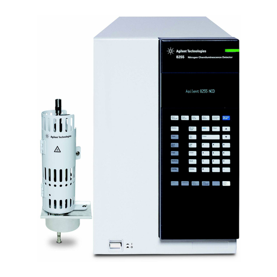
- Page 1 Agilent 8355 Sulfur and 8255 Nitrogen Chemiluminescence Detectors User Manual Agilent Technologies...
- Page 2 A CAUTION notice denotes a hazard. without prior agreement and written permitted by applicable law, Agilent It calls attention to an operating consent from Agilent Technologies, Inc. as disclaims all warranties, either express procedure, practice, or the like that, if governed by United States and...
-
Page 3: Table Of Contents
Contents Getting Started Manuals, Information, Tools and Where to Find Them GC Manuals, Tools, and Online Help User Apps Education Opportunities Overview of the 8355 SCD and 8255 NCD Overview of Installation and First Startup Safety and Regulatory Information Introduction Important Safety Information Many internal parts of the detector carry dangerous voltages Electrostatic discharge is a threat to GC electronics... - Page 4 System Description Specifications 8355 SCD 8255 NCD Theory of Operation Description of Major Components Burner assembly Ozone generator Reaction cell and photomultiplier tube (PMT) EPC modules Vacuum pump Ozone destruction trap Oil coalescing filter FID adapter (optional) NCD chiller Operation Introduction Integrated version Setting Parameters...
- Page 5 Maintenance Maintenance Log and Early Maintenance Feedback (EMF) Maintenance Schedule Tracking Detector Sensitivity Consumables and Replacement Parts Exploded Parts View of the SCD Exploded Parts View of the NCD Detector Maintenance Method Attach a Column to the Detector Replace the Inner Ceramic Tube (SCD) Replace the Quartz Tube (NCD) Check the Vacuum Pump Oil Add Vacuum Pump Oil...
- Page 6 Coking Hydrogen Poisoning Contaminated Gases Performance Verification About Chromatographic Checkout Prepare for Chromatographic Checkout Prepare sample vials Check SCD Performance Check NCD Performance SCD and NCD User Manual...
-
Page 7: Getting Started
Manuals, Information, Tools and Where to Find Them Overview of the 8355 SCD and 8255 NCD Overview of Installation and First Startup This chapter introduces the Agilent 8355 Sulfur Chemiluminescence Detector (SCD) and the Agilent 8255 Nitrogen Chemiluminescence Detector (NCD), and provides details about where to find helpful information and tools, such as GC manuals, flow calculators, and so forth. -
Page 8: Manuals, Information, Tools And Where To Find Them
Getting Started Manuals, Information, Tools and Where to Find Them This manual describes how to operate the Agilent 8355 Sulfur Chemiluminescence Detector (SCD) and the Agilent 8255 Nitrogen Chemiluminescence Detector (NCD) as installed on an Agilent 7890B Gas Chromatograph (GC). This manual also provides operating recommendations, maintenance procedures, and troubleshooting. - Page 9 日本語 To install: 1. Insert disk into DVD drive 2. Follow the instructions on the screen. © 2013 Agilent Technologies, Inc. 3. If autoplay is not enabled, double-click All rights reserved. "index_xx.html" on the DVD where xx is:...
- Page 10 Getting Started Available manuals Table 1 7890B GC Learning Products Learning product Contents When to use this documentation Getting Started Overview of the manuals. Where to find information. How to install the manuals. Overview of the GC. • Safety Manual Lists safety and regulatory Before installation, to prepare for a information.
- Page 11 Getting Started Table 1 7890B GC Learning Products Learning product Contents When to use this documentation • Advanced Operation Manual Procedures and theory of operation When developing methods. not normally required for daily use: • When running the GC standalone (no programming;...
- Page 12 Getting Started Table 2 Languages available for GC manuals Manual Format Getting Started Print HTML Safety Manual HTML Installation and First Startup HTML GC, GC/MS, and ALS Site Prep Guide HTML Maintaining Your GC HTML Troubleshooting HTML SCD and NCD User Manual...
- Page 13 Getting Started Table 2 Languages available for GC manuals Manual Format Operation Manual HTML Advanced Operation Manual HTML Software Familiarization HTML Online help In addition to hardware manuals, your GC data system also includes an extensive online help system with detailed information, common tasks, and video tutorials on using the software.
-
Page 14: User Apps
Getting Started User Apps In addition to the Hardware Manuals, you will also find several User Apps on the Agilent GC and GC/MS User Manuals & Tools DVDs. See below for a list of available Apps, such as Parts Finder, the GC Firmware Update Tool, and a variety of Method Developer Tools. - Page 15 Getting Started SCD and NCD User Manual...
- Page 16 Getting Started Install the GC Firmware Update tool to install your GC and sampler systems. Install Method Developer Tools, such as the Method Translator, to help you convert a helium carrier gas method to use hydrogen. SCD and NCD User Manual...
-
Page 17: Education Opportunities
Getting Started Education Opportunities Agilent has designed customer courses to help you learn how to use your GC to maximize your productivity while learning about all of the great features of your new system: R1778A — Agilent 7890 A/B GC and OpenLAB ChemStation Operation R1914A —... -
Page 18: Overview Of The 8355 Scd And 8255 Ncd
Getting Started Overview of the 8355 SCD and 8255 NCD Figure 1 through Figure 5 show the controls, parts, and components of the 8355 SCD and 8255 NCD used or accessed during installation, operation, and maintenance. Status LED Status LED Power switch Power switch 8355 SCD... - Page 19 Getting Started Hydrogen gas input Burner heater connector Oxidizer gas input Heater/sensor connector Ozone gas input Through-hole for sample transfer line Thermocouple connector Communications cable Vacuum connection Vacuum pump Power connection power connection Figure 2 Detector back view SCD and NCD User Manual...
- Page 20 Getting Started Upper hydrogen output Hydrogen gas input (SCD only) Oxidizer gas output Oxidizer gas input Lower hydrogen output Ozone gas input Figure 3 Detector gas connections plug Pump oil pan Figure 4 RV5 Vacuum pump SCD and NCD User Manual...
- Page 21 Getting Started Maximum oil level mark Sight gage Oil level Minimum oil level mark Figure 5 RV5 Vacuum pump oil sight gage SCD and NCD User Manual...
-
Page 22: Overview Of Installation And First Startup
Getting Started Overview of Installation and First Startup Below is an overview of the installation process. See the Installation and First Startup Guide for complete installation details. If not already installed, install the GC and Agilent data system. (If another detector is present, verify its performance.) Place the detector on the bench. -
Page 23: Safety And Regulatory Information
Cleaning Recycling the Product Technical Assistance This chapter provides important safety and regulatory information required for installation and use of the Agilent 8355 SCD and the Agilent 8255 NCD. Read and understand this information before operating the detector. Agilent Technologies... -
Page 24: Introduction
SCD or NCD, see the Installation Guide for instructions. In addition to the information here, refer to the GC safety information that shipped with the GC. Find the Agilent GC manuals on the Agilent Technologies GC and GC/MS User Manuals & Tools DVDs. SCD and NCD User Manual... -
Page 25: Important Safety Information
Safety and Regulatory Information Important Safety Information There are several important safety notices that you should always keep in mind when using the 8355 SCD or 8255 NCD. Many internal parts of the detector carry dangerous voltages If the GC and detector are connected to a power source, even if the power switches are off, potentially dangerous voltages exist on the: •... -
Page 26: Electrostatic Discharge Is A Threat To Gc Electronics
Safety and Regulatory Information Electrostatic discharge is a threat to GC electronics The printed circuit (PC) boards in the detector can be damaged by electrostatic discharge. Do not touch any of the boards unless it is absolutely necessary. If you must handle them, wear a grounded wrist strap and take other antistatic precautions. - Page 27 Safety and Regulatory Information Hydrogen is a commonly used GC carrier gas. Hydrogen is potentially explosive and has other dangerous characteristics. • Hydrogen is combustible over a wide range of concentrations. At atmospheric pressure, hydrogen is combustible at concentrations from 4 % to 74.2 % by volume. •...
-
Page 28: Ozone
Safety and Regulatory Information Measuring hydrogen gas flows Do not measure hydrogen together with air or oxygen. This can WA RNING create explosive mixtures that may be ignited by the automatic igniter. To avoid this hazard: 1. Turn the automatic igniter off before you begin. -
Page 29: Symbols
Failure to comply with these precautions violates safety standards of design and the intended use of the instrument. Agilent Technologies assumes no liability for the customer’s failure to comply with these requirements. See accompanying instructions for more information. -
Page 30: Fuses
Safety and Regulatory Information Fuses The 8355 SCD and 8255 NCD require fuses for proper operation. These must only be accessed by Agilent trained service personnel. For continued protection against fire hazard, replace fuses only WA RNING with fuses of the same type and rating. Electrical shock hazard. -
Page 31: Safety And Regulatory Information
Safety and Regulatory Information Safety and Regulatory Information This instrument has been designed and tested in accordance with IEC Publication 61010-1 Safety Requirements for Electrical equipment for Measurement, Control, & Laboratory Use, and has been supplied in a safe condition. The instruction documentation contains information and warnings which must be followed by the user to ensure safe operation and to maintain the instrument in a safe condition. -
Page 32: Sound Emission Certification For Federal Republic Of Germany
Safety and Regulatory Information The Agilent 8355 SCD and 8255 NCD are designed and manufactured under a quality system registered to ISO 9001. Declaration of Conformity available. Instructions for Disposal of Waste Equipment by Users in the European Union: This symbol on the product or its packaging indicates that this product must not be disposed of with other waste. - Page 33 Make sure that all peripheral devices are also certified. Make sure that appropriate cables are used to connect the device to peripheral equipment. Consult your equipment dealer, Agilent Technologies, or an experienced technician for assistance. Changes or modifications not expressly approved by Agilent Technologies could void the user’s authority to operate the...
-
Page 34: Intended Use
Safety and Regulatory Information Intended Use Agilent products must only be used in the manner described in the Agilent product user guides. Any other use may result in damage to the product or personal injury. Agilent is not responsible for any damages caused, in whole or in part, by improper use of the products, unauthorized alterations, adjustments or modifications to the products, failure to comply with procedures in Agilent product user guides, or use of the... - Page 35 Agilent 8355 SCD and 8255 NCD User Manual System Description Specifications Theory of Operation Description of Major Components This chapter provides typical performance specifications, and describes the theory of operation for the 8355 SCD and 8255 NCD. Agilent Technologies...
-
Page 36: System Description
System Description Specifications This section lists the published specifications for a new detector, installed on a new Agilent 7890B GC, when used in a typical laboratory environment. 8355 SCD Specification Minimum Detection Limit (MDL), < 0.5 pg (S)/s (2x Agilent data system typical ASTM noise) Linearity... -
Page 37: Theory Of Operation
System Description Theory of Operation The Agilent 8255 and 8355 chemiluminescence detectors detect target molecules by chemically transforming them in several steps to an excited species that emits light. The light from this emission is converted to an electrical signal by a photomultiplier tube (PMT). - Page 38 System Description the spectrum. The light emitted is directly proportionally to the amount of nitrogen in the sample: NO + O NO + O + h (~600 to 3,000 nm) The light (h ) emitted by the chemical reaction is optically filtered and detected by a PMT.
-
Page 39: Description Of Major Components
System Description Description of Major Components Burner assembly The burner assembly mounts on top of the GC in a detector location, and contains the column connection. For the SCD, the burner provides two heated zones, one at the base and one farther up the assembly. In the burner base region, the column effluent mixes with the lower hydrogen flow and air at high temperature. - Page 40 System Description To detector Upper hydrogen Ceramic tube, upper Burner Ceramic tube, lower Oxidizer Base heater Lower hydrogen Column Figure 6 SCD flows For the NCD, the burner provides two heated zones, one at the base and one farther up the assembly. In the burner base region, the column effluent mixes with hydrogen and air at high temperature.
-
Page 41: Ozone Generator
System Description To detector Quartz tube Burner Oxidizer Base heater Hydrogen Column Figure 7 NCD Flows Ozone generator The ozone generator provides ozone that reacts with any SO or NO in the reaction cell to generate SO * and NO * respectively. -
Page 42: Reaction Cell And Photomultiplier Tube (Pmt)
System Description Reaction cell and photomultiplier tube (PMT) The ozone generator discharges ozone into the reaction cell. This ozone reacts with any SO or NO to generate SO * and NO respectively. As the species return to ground state though chemiluminescence, the photomultiplier tube produces a current proportional to the intensity of emitted light. -
Page 43: Ncd Chiller
System Description simultaneous detection of hydrocarbon components using a single column without splitting. For this reason, Agilent offers an optional FID adapter to mount the burner assembly onto an FID for the simultaneous collection of FID and SCD chromatograms. During dedicated SCD operation, 100 % of the column effluent passes through the burner to the detector. - Page 44 System Description SCD and NCD User Manual...
-
Page 45: Operation
NCD. This chapter assumes familiarity with using the data system, if used, and the GC front panel keyboard and display. For more information, please see the data system online help and the instrument documentation available on the Agilent GC and GC/MS User Manuals and Tools DVDs. Agilent Technologies... -
Page 46: Introduction
Operation Introduction Integrated version When installed on an Agilent 7890B or 7890A+ GC, program and operate the SCD and NCD as you would any other detector on the GC. For Agilent data system users, use the integrated GC driver to access the operating parameters. For standalone GC users, access these parameters from the GC front panel and keyboard. -
Page 47: Setting Parameters
Operation Setting Parameters This section lists the parameter ranges for the SCD and NCD. The available setpoints provide a wide range suitable for a large variety of applications as well as for method development. See “Adjusting the Operating Conditions” on page 53 for important details about the relationships between the setpoints. -
Page 48: Software Control
Operation Software control When using an Agilent data system, open an online session and edit the instrument acquisition parameters to change method settings. Select the detector from the method editor, typically Detectors > Front Detector (or Back Detector or Aux Detector, as appropriate for your setup). - Page 49 Operation Figure 9 Example NCD parameters in a data system For tandem configurations, for example a front FID-SCD, the FID will be the front detector, and the XCD will be an Aux detector. To access configuration parameters using data system control, select Configuration >...
-
Page 50: Gc Keyboard Control
Operation GC keyboard control To access the method parameters for an SCD or NCD, press the [Front Det], [Back Det], or [Aux Det #] (tandem FID-XCD configuration only) key. See Table To turn on the PMT voltage, press [Config], then press the key for the detector ([Front Det], [Back Det], or [Aux Det #]). -
Page 51: Detector Stability And Response
Operation Detector Stability and Response The time required for system stabilization varies depending on the application, system cleanliness, the presence of active sites, and other factors. • When starting an existing system, typically wait at least 10 minutes before using the system to collect data. •... -
Page 52: Typical Operating Conditions
Operation Typical Operating Conditions Table 6 lists the recommended starting conditions for SCD and NCD methods. These conditions should provide acceptable results for a wide variety of applications. However, optimize these conditions as needed to improve the performance of the specific application. -
Page 53: Adjusting The Operating Conditions
Operation Adjusting the Operating Conditions Table 4 on page 47 lists the range of values for each parameter, as limited by the GC firmware. To provide flexibility during method development for particular application, the range is wider than needed for most applications. However, hydrogen flows in the SCD need particular attention. -
Page 54: Start-Up
Operation Start-up How to start the detector depends on whether or not you have created a method for the detector. If a valid method exists: After you have used the SCD/NCD (at least one valid method exists), start the detector by loading the method. -
Page 55: Resource Conservation
Operation Resource Conservation To conserve resources during periods of inactivity, for example, overnight or over a weekend, use the 7890B GC’s resource conservation features to load a sleep method. (See the GC Operation Manual for details on using sleep and wake methods.) A sleep method for an SCD or NCD should do the following: •... -
Page 56: Shutdown
Operation Shutdown When turning off the detector for a long period of time, or to perform maintenance on the GC or detector, shut down the detector as follows: Access the method parameters. At the GC front panel, press [Front Det] or [Back Det], or •... -
Page 57: Configure Auto Flow Zero On The Gc
Operation Configure Auto Flow Zero on the GC Agilent recommends setting the GC to automatically zero flow sensors to reduce drift. See the GC Operation Manual for details. On the GC keypad, press [Options]. Scroll to Calibration and press [Enter]. Scroll to select the appropriate detector (front, back, aux 2, or aux 1) and press [Enter]. -
Page 58: Configure The Detector
Operation Configure the Detector For an SCD or NCD, gas types are usually set once. The SCD uses oxygen for the ozone supply gas and air for the oxidizer gas, while the NCD uses oxygen for both. To configure the gas types for an SCD or NCD by using the GC keyboard: At the GC keyboard, press the keys to access the detector, for example [Config][Front Det]. - Page 59 Operation The PMT voltage can be turned on or off only at the GC front panel. To enable or disable the PMT voltage: At the GC keyboard, press the keys to access the detector, for example, press [Config][Front Det] for an XCD mounted in the front position, or press [Config][Back Det] for an XCD mounted in the back position.
- Page 60 Operation SCD and NCD User Manual...
-
Page 61: Maintenance
Replace the Vacuum Pump Oil Replace the Ozone Trap Change the Oil Mist Filter Clean the Detector Exterior Calibrate the Flow and Pressure Sensors Updating Firmware This chapter describes the routine maintenance procedures needed for normal use of the SCD and NCD. Agilent Technologies... -
Page 62: Maintenance Log And Early Maintenance Feedback (Emf)
Maintenance Maintenance Log and Early Maintenance Feedback (EMF) When using the detector with an Agilent 7890B GC, use the Early Maintenance Feedback (EMF) feature to track routine maintenance. The EMF feature is available at the GC front panel and in any Agilent data system, and can help you replace the filters and oil before contamination becomes a problem. -
Page 63: Maintenance Schedule
Maintenance Maintenance Schedule To maintain optimum performance of the Agilent 8355 SCD and 8255 NCD, routinely replace the ozone trap, oil coalescing filter, and vacuum pump oil. Refer to Table 7 for the expected life span of each item. Table 7 Recommended Edwards RV5 vacuum pump maintenance schedule Component... -
Page 64: Tracking Detector Sensitivity
Maintenance Tracking Detector Sensitivity In addition to using the EMF features of the GC and detector, also track detector sensitivity. Sensitivity reflects the performance characteristics of a given system, and decreased sensitivity may indicate the need for routine detector maintenance. Sensitivity is typically reported as: peak area Sensitivity = amount... -
Page 65: Consumables And Replacement Parts
Maintenance Consumables and Replacement Parts See the Agilent catalog for consumables and supplies for a more complete listing, or visit the Agilent Web site for the latest information (http://www.chem.agilent.com/store). Table 8 Consumables and parts for the SCD and NCD Description/quantity Part number Detector parts Ceramic tube, inner, small (SCD) - Page 66 Maintenance Table 9 Filters for the SCD and NCD Description/quantity Part number Gas Clean filter, sulfur (filters sulfur and moisture) CP17989 Gas Clean Filter SCD Kit, for sulfur CP17990 chemiluminescence detectors Table 10 Nuts, ferrules, and hardware for capillary columns Column id (mm) Description Typical use...
-
Page 67: Exploded Parts View Of The Scd
Maintenance Exploded Parts View of the SCD (For tandem FID-SCD, see the FID details) Figure 12 SCD Exploded parts view SCD and NCD User Manual... -
Page 68: Exploded Parts View Of The Ncd
Maintenance Exploded Parts View of the NCD Coupling 1/4-inch graphite ferrule, straight Quartz tube Shroud assembly Burner heater Burner lower nut 1/4-inch graphite ferrule, straight Jet assembly and coupling Detector base Insulation, top Insulation, bottom Insulation cup Ferrule Column nut Column installation tool Figure 13 NCD exploded parts view... -
Page 69: Detector Maintenance Method
Maintenance Detector Maintenance Method It is good practice to create a maintenance method for the GC that prepares the GC and detector for maintenance. Load this method before performing maintenance. A maintenance method for the SCD should do the following: Turn off the heater and burner to allow them to cool. -
Page 70: Attach A Column To The Detector
Maintenance Attach a Column to the Detector This procedure describes how to attach a column directly to an XCD. In a N O T E tandem FID-XCD installation, install the column into the FID as described in the FID instructions. See the GC documentation. Gather the following materials (see “Consumables and parts for the SCD and NCD”... - Page 71 Maintenance Prepare the detector for maintenance. Load the GC maintenance method and wait for the GC to become ready. (See “Detector Maintenance Method” page 69.) Wait until the inlets, oven, detectors, valve box, burner assembly, and detector base cool to a safe handling temperature (<...
- Page 72 Maintenance Tighten the column nut into the column measuring tool until the column nut grips the column. Tighten the nut an additional 1/8- to 1/4-turn with a pair of wrenches. Snug the septum against the base of the column nut. Use a column cutting wafer at 45°...
-
Page 73: Replace The Inner Ceramic Tube (Scd)
Maintenance Replace the Inner Ceramic Tube (SCD) To replace the inner ceramic tube: The oven, inlets, and detectors can be hot enough to cause burns. WA RNING Cool these areas to a safe handling temperature before beginning. Wear clean, lint-free gloves to prevent contamination of parts with C A U T I O N dirt and skin oils. - Page 74 Maintenance Hydrogen gas is flammable. Turn off all detector (and column) WA RNING hydrogen gas flows before performing maintenance on the detector. Disconnect the transfer line and quickly cover the open end with the 1/8-inch cap. Use a 3/8-inch wrench on the transfer line and a 7/16-inch wrench on the upper fitting to hold the burner assembly steady.
- Page 75 Maintenance Reinstall the transfer line onto the outlet fitting. Tighten until snug (finger-tight). Do not overtighten. Restore the detector gas flows. Check for leaks at the upper hydrogen fitting. Correct a leak as needed. Restore the remaining detector operating conditions. Reset the EMF counter.
-
Page 76: Replace The Quartz Tube (Ncd)
Maintenance Replace the Quartz Tube (NCD) To replace the NCD quartz tube: The oven, inlets, and detectors can be hot enough to cause burns. WA RNING Cool these areas to a safe handling temperature before beginning. Wear clean, lint-free gloves to prevent contamination of parts with C A U T I O N dirt and skin oils. - Page 77 Maintenance Hydrogen gas is flammable. Turn off all detector (and column) WA RNING hydrogen gas flows before performing maintenance on the detector. Remove the protective shroud. Remove the two T20 Torx screws, twist the shroud counter-clockwise to remove it from the mounting posts, then lift.
- Page 78 Maintenance Gently pull the quartz tube up through the burner assembly to remove. The graphite ferrule should remain in the rotating nut in the burner base. Use a dental tool or similar to remove the old graphite ferrule from the rotating nut in the burner base. Use two wrenches to disassemble the reducer, then remove the old ferrule.
- Page 79 Maintenance Reinstall the protective shroud. Restore the detector operating conditions. Reset the EMF counter. SCD and NCD User Manual...
-
Page 80: Check The Vacuum Pump Oil
Maintenance Check the Vacuum Pump Oil Never add or replace the foreline pump oil while the pump is on. C A U T I O N Check the level and color of the pump oil weekly. Check the oil level in the window of the foreline pump. The oil level should be between the marks for Max and Min. -
Page 81: Add Vacuum Pump Oil
Maintenance Add Vacuum Pump Oil Add pump oil when the pump oil level is low. Materials needed • Funnel (9301-6461) • 5-mm Allen wrench (8710-1838) • Gloves, chemical resistant, clean, lint free (9300-1751) • Oil, synthetic, Mobile 1 (G6600-85001) • Safety glasses (goggles) Never add pump oil while the pump is on. - Page 82 Maintenance Remove the fill cap on the vacuum pump. Power cord receptacle Fill cap Add new pump oil until the oil level is near, but not over the maximum mark beside the oil level window. See Figure 16 page 80. Reinstall the fill cap.
-
Page 83: Replace The Vacuum Pump Oil
Maintenance Replace the Vacuum Pump Oil Replace the pump oil every three months or sooner if the oil appears dark or cloudy. Materials needed • Container for catching used pump oil • Funnel (9301-6461), 5-mm Allen wrench (8710-1838) • Gloves, chemical resistant, clean, lint free (9300-1751) •... - Page 84 Maintenance Place a container under the drain plug of the vacuum pump. Fill cap Drain plug Remove the fill cap, then open the drain plug. Drain the oil completely by raising the motor end of the pump. Reinstall the drain plug. Add new pump oil until the oil level is near, but not over the maximum mark beside the oil level window.
-
Page 85: Replace The Ozone Trap
Maintenance Replace the Ozone Trap To replace the ozone trap: Load a method to cool the detector, turn off the heaters, and turn off the hydrogen flow. • Turn off the heaters and allow the burner to cool. • Leave the oxidizer flow on. •... - Page 86 Maintenance elbow must be nearest the pump intake.) If you removed the short connector hose from the pump intake, reinstall it. SCD and NCD User Manual...
-
Page 87: Change The Oil Mist Filter
Maintenance Change the Oil Mist Filter The oil mist filter on the RV5 pump has two components: the charcoal odor filter and the oil coalescing filter element. To replace the filters, disassemble the oil mist filter assembly with the 4 mm long-handled hex wrench (provided). The smaller charcoal odor filter sits on top of the larger oil coalescing filter element. -
Page 88: Clean The Detector Exterior
Maintenance Clean the Detector Exterior Burn hazard. The burner assembly can be hot enough to cause WA RNING burns. Before touching, cool to a safe handling temperature (< 40 °C). Shock hazard. Before cleaning the detector, turn it off and unplug WA RNING its power cord. -
Page 89: Calibrate The Flow And Pressure Sensors
Maintenance Calibrate the Flow and Pressure Sensors The 8355 SCD and 8255 NCD use electronic pressure control modules. Typically, set the 7890B GC to use automatic flow zeroing. Calibration is generally not required. However, if needed the flow and pressure sensors can be manually zeroed. See the GC Operation Manual for details. -
Page 90: Updating Firmware
Maintenance Updating Firmware The GC firmware controls the detector. Any updates for the detector will be applied through the GC firmware. See the GC Firmware Update Tool on the Agilent GC and GC/MS User Manuals & Tools DVDs, or download the tool from the Agilent web site GC support pages. -
Page 91: Troubleshooting
Solving Detector Problems Troubleshooting Table Status Indicator LED Detector Messages Leaks Power Problems Ozone Generation Problems Coking Hydrogen Poisoning Contaminated Gases This chapter describes how to troubleshoot and resolve typical issues encountered while using an Agilent SCD or NCD. Agilent Technologies... -
Page 92: Solving Detector Problems
Troubleshooting Solving Detector Problems A basic understanding of the detector helps to diagnose and solve detector problems. Review the basic detector theory found “Theory of Operation” on page 37. Also, please note that this section is intended to troubleshoot problems in a detector that has previously been performing acceptably. -
Page 93: Troubleshooting Table
Troubleshooting Troubleshooting Table Table 11 Troubleshooting Detector Issues Problem Possible cause Diagnosis Corrective action Detector problems No response No ozone Little or no difference in “No ozone”. output signal between ozone On and Off. No ozone High voltage transformer No difference in output Contact Agilent for service. - Page 94 Troubleshooting Table 11 Troubleshooting Detector Issues Problem Possible cause Diagnosis Corrective action Leak in the hydrogen supply Check for leaks in the lines. detector and repair any leaks. See “Leaks” page 98. Tailing peaks with Severe contamination of High background signal Check inline supply traps non-equimolar response detector gases.
- Page 95 Troubleshooting Table 12 Troubleshooting Pump Issues Problem Possible Cause Diagnosis Corrective Action Vacuum pump problems Pump does not start Pump switch off or power Turn On pump power switch. cord disconnected. Check pump power cord. Fuses blow on startup Emulsified oil. Inspect oil for integrity.
-
Page 96: Status Indicator Led
Troubleshooting Status Indicator LED Use the detector status LED to quickly determine the status and readiness of the detector. The LED changes color depending on the current state of the detector. • Green: Indicates that power is available for the heaters, chiller (NCD), vacuum pump, and ozone generator. -
Page 97: Detector Messages
Troubleshooting Detector Messages Check the GC status display for detector messages. The GC will display and status and error messages that occur during operation, as well as log detector maintenance and error messages in the GC log files. See the GC operating manuals for details. -
Page 98: Leaks
Troubleshooting Leaks Ozone leaks Ozone is a hazardous gas and a strong oxidant. Exposure to ozone WA RNING should be minimized by using the instrument in a well-ventilated area and by venting the exhaust of the vacuum pump to a fume hood. -
Page 99: Checking For Hydrogen And Oxidizer Leaks
Troubleshooting page 99. If you suspect a leak inside the detector mainframe, contact Agilent for service. Do not open the detector mainframe. Checking for hydrogen and oxidizer leaks To check for a leak in the hydrogen or oxidizer flow paths, do the following: Check all external fittings for leaks. -
Page 100: Power Problems
Troubleshooting Power Problems When troubleshooting power problems on an SCD or NCD, remember that the power supplied to the detector electronics and flow modules comes from the GC and is controlled by the GC power switch. The power supplied to the SCD/NCD heaters, NCD chiller, vacuum pump, and ozone generator comes from the detector mainframe and is controlled by the detector power switch. -
Page 101: Ozone Generation Problems
Troubleshooting Ozone Generation Problems Before troubleshooting the ozone generator, first verify that the other components of the system operate normally. For example, check for leaks in the detector external connections, check for leaks in the inlet and inlet column fitting, check that the vacuum pump operates normally, check that the inlet and ALS are operating normally, and so on. -
Page 102: Coking
Troubleshooting Coking Contamination from some sample matrices can reduce sensitivity. For example, crude oils containing volatile metal complexes may contaminate the ceramic tubes. In addition, incomplete combustion of certain hydrocarbon-containing compounds leaves behind coke deposits on the ceramic tubes. Coke deposits may be removed from the burner by reducing the hydrogen flow rate. -
Page 103: Hydrogen Poisoning
Troubleshooting Hydrogen Poisoning Hydrogen poisoning of the SCD ceramic tubes can occur when the relative oxidizer flow is very much lower than the hydrogen flow. Whether this state occurs due to inappropriate method setpoints or due to a problem with the oxidizer flow, this condition results in extremely reduced or no response. -
Page 104: Contaminated Gases
Troubleshooting Contaminated Gases Agilent recommends the use of clean gases that meet the requirements in the Site Preparation Guide. In addition, Agilent highly recommends the use of high quality traps to eliminate as much possible contamination as possible. The use of clean gases is essential for optimal performance. -
Page 105: Performance Verification
Agilent 8355 SCD and 8255 NCD User Manual Performance Verification About Chromatographic Checkout Prepare for Chromatographic Checkout Check SCD Performance Check NCD Performance This chapter describes how to verify that the detector is operating normally. Agilent Technologies... -
Page 106: About Chromatographic Checkout
Performance Verification About Chromatographic Checkout The tests described in this section provide basic confirmation that the GC and detector can perform comparably to factory condition. However, as detectors and the other parts of the GC age, detector performance can change. The results presented here represent typical outputs for typical operating conditions and are not specifications. -
Page 107: Prepare For Chromatographic Checkout
Performance Verification Prepare for Chromatographic Checkout Because of the differences in chromatographic performance associated with different consumables, Agilent strongly recommends using the parts listed here for all checkout tests. Agilent also recommends installing new consumable parts whenever the quality of the installed ones is not known. For example, installing a new liner and septum ensures that they will not contribute any contamination to the results. -
Page 108: Prepare Sample Vials
Performance Verification Table 13 Recommended parts for checkout by inlet type (continued) Recommended part for checkout Part number Syringe, 5-µL on-column 5182-0836 0.32-mm needle for 5-µL syringe 5182-0831 7693A ALS: Needle support insert, COC G4513-40529 7683B ALS: Needle support assembly for G2913-60977 0.25/0.32 mm injections Insert, fused silica, 0.32-mm id... -
Page 109: Check Scd Performance
Performance Verification Check SCD Performance Gather the following: • Evaluation column, DB-1 30 m × 0.32 mm × 1.0 μm (part number 123-1033) • SCD performance evaluation (checkout) sample (5190-7003): 0.7 ± 0.002 mg/L diethyl disulfide and 1.0 ± 0.003 mg/L tert-butyldisulfide in isooctane. •... - Page 110 Performance Verification burner cleanliness. Noise will also greatly decrease over time. For a well-stabilized system, noise measured by Agilent OpenLAB CDS should be approximately 5 display units or less. Checkout can continue before the baseline becomes completely stable. Create or load a method with the parameter values listed in Table Table 14 SCD Checkout conditions...
- Page 111 Performance Verification Table 14 SCD Checkout conditions (continued) Burner temperature 800 °C Upper H flow 38 mL/min Lower H flow 8 mL/min Oxidizer flow 50 mL/min, Air O3 Generator O3 Generator flow Vacuum pump FID-SCD Tandem settings FID temp 350 °C FID hydrogen flow 35 mL/min FID air flow...
- Page 112 Performance Verification Table 14 SCD Checkout conditions (continued) Solvent B post washes Solvent B wash volume 8 µL (maximum) Injection mode (7693A) Normal Airgap Volume (7693A) Viscosity delay Solvent Wash Draw Speed (7693A) Solvent Wash Dispense Speed 1500 (7693A) Sample Wash Draw Speed (7693A) Sample Wash Dispense Speed 1500 (7693A)
- Page 113 Performance Verification The following chromatogram shows typical results for a new detector with new consumable parts installed. Note that the response for a tandem FID-SCD installation will be approximately 1/10 of the response shown in this example due to the reduced amount of sample that reaches the SCD. SCD1 A, Front Signal (C:\CHEM32\2\DATA\XCD-DATA-FEB2015\SCD\EXAMPLE.D) 2500 2000...
-
Page 114: Check Ncd Performance
Performance Verification Check NCD Performance Gather the following: • Evaluation column, HP-5 30 m × 0.32 mm × 0.25 μm (part number 19091J-413) • NCD performance evaluation (checkout) sample (5190-7002): 3-methylindole 10.0 ± 0.1 mg/L, 9-methylcarbazole 14.1 ± 0.1 mg/L, and nitrobenzene 9.51 ±... - Page 115 Performance Verification However, a new burner (or a burner with a new quartz tube) can have a very high baseline after first ignition. In this case, the baseline should gradually decrease, depending on burner cleanliness. Noise will also greatly decrease over time. For a well-stabilized system, noise measured by Agilent OpenLAB CDS should be approximately 4 display units or less.
- Page 116 Performance Verification Table 15 NCD Checkout conditions (continued) Septum purge 15 mL/min Detector Base temperature 280°C Burner temperature 900 °C Chiller temperature flow 3 mL/min Oxidizer flow 8 mL/min, Oxygen O3 Generator O3 Generator flow Vacuum pump Oven Initial temp 50 °C Initial time 3.0 min...
- Page 117 Performance Verification Table 15 NCD Checkout conditions (continued) Solvent Wash Draw Speed (7693A) Solvent Wash Dispense Speed 1500 (7693A) Sample Wash Draw Speed (7693A) Sample Wash Dispense Speed 1500 (7693A) Inject Dispense Speed (7693A) 3000 Plunger speed (7683) Fast, for all inlets except COC. PreInjection dwell PostInjection dwell Manual injection...
- Page 118 Agilent Technologies The following chromatogram shows typical results for a new detector with new consumable parts installed. NCD1 A, Front Signal (C:\CHEM32\2\DATA\XCD-DATA-FEB2015\NCD\EXAMPLE.D) 4000 3000 2000 1000 Agilent Technologies, Inc. Printed in USA December 2015...