Table of Contents
Advertisement
Quick Links
Advertisement
Table of Contents

Related Manuals for Agilent Technologies 85025A


Summary of Contents for Agilent Technologies 85025A
- Page 1 User’s and Service Guide Agilent Technologies 85025A/B/D/E Detectors Manufacturing Part Number: 85025-90063 Supersedes 85025-90014 & 85025-90031 Printed in USA Print Date: January 2013 Supersedes September 2002 © Agilent Technologies, Inc. 1995, 2002, 2013...
- Page 2 This manual may contain references to HP or Hewlett-Packard. Please note that Hewlett-Packard's former test and measurement, semiconductor products and chemical analysis businesses are now part of Agilent Technologies. To reduce potential confusion, the only change to product numbers and names has been in the company name prefix: where a product number/name was HP XXXX the current name/number is now Agilent XXXX.
- Page 3 FAR 52.227-19 (June 1987) or any equivalent agency regulation or contract clause. Use, duplication or disclosure of Software is subject to Agilent Technologies’ standard commercial license terms, and non-DOD Departments and Agencies of the U.S. Government will receive no greater than Restricted Rights as defined in FAR 52.227-19(c)(1-2) (June 1987).
- Page 4 \softkey," a key whose label is determined by oftkey the instrument's rmware. his indicates text displayed on the instrument's screen. creen Text Documentation Description his manual contains information on operating, testing, and servicing the Agilent 85025A/B/D/E detectors.
-
Page 5: Table Of Contents
Procedure ......If the Operator's Check Fails ....Ag lent 85025A/B/D/E Contents-1... - Page 6 Equipment Required ..... 4-11 Equipment Common to 85025A/B/D/E ... . 4-11 Additional est Equipment Required for 85025A .
- Page 7 Gaging Connectors ..... . . Gaging Connectors to be Mated with the 85025A/B/D/E ..ype-N female ..... . .
- Page 8 Figures 1-1. 85025A/B/D/E Detector ....2-1. Example of a Static-Safe Work Station ... .
- Page 9 1-1. 85025 Series Detector Descriptions ....1-2. 85025A/B/D/E Detector General Speci cations ..1-3. 85025A Detector Speci cations (including Option 001) ..
-
Page 11: General Information
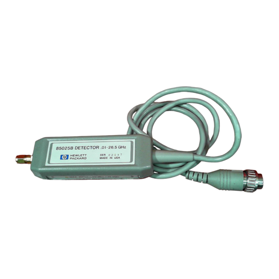
Agilent 85025A/B/D/E detectors. Figure 1-1 shows the detectors. Product Description he 85025A/B/D/E detectors are speci cally designed for use with Agilent 8757 series scalar network analyzers. Table 1-1. 85025 Series Detector Descriptions... - Page 12 Figure 1-1. 85025A/B/D/E Detector General Informat on Ag lent 85025A/B/D/E...
-
Page 13: Speci Cations And Supplemental Characteristics
Note Speci cations describe the instrument's warranted performance over the temperature range of 25 C, 5 C. Table 1-2. 85025A/B/D/E Detector General Speci cations ynamic Range on all 8757 Series analyzer's detector inputs): AC mode +16 to... - Page 14 Table 1-3. 85025A Detector Speci cations (including Option 001) Frequency Range 0.01 to 18 GHz Return Loss 10 MHz to 40 MHz 10 dB 40 MHz to 4 GHz 20 dB 4 GHz to 18 GHz 17 dB Frequency Response in DC mode, input power...
- Page 15 DC mode, input power 10 dBm): 10 MHz to 40 MHz +0.25 dB/ 0.75 dB 40 MHz to 18 GHz 0.5 dB Absolute Power Accuracy in DC mode, 50 MHz, calibrated at 0 dBm) ynamic Power Accuracy Ag lent 85025A/B/D/E General Informat on...
- Page 16 20 GHz to 26.5 GHz 0.5 dB 26.5 GHz to 40 GHz +2.5/ 0.5 dB 40 GHz to 50 GHz +3.0/ 0.5 dB Absolute Power Accuracy in DC mode, 50 MHz, calibrated at 0 dBm) ynamic Power Accuracy General Informat on Ag lent 85025A/B/D/E...
- Page 17 40 MHz to 18 GHz 0.5 dB 18 GHz to 26.5 GHz 0.5 dB at 18 GHz to 1.4 dB at 26.5 GHz Absolute Power Accuracy in DC mode, 50 MHz, calibrated at 0 dBm) ynamic Power Accuracy Ag lent 85025A/B/D/E General Informat on...
- Page 18 0.207-inch o set, the gage displays a 0.207- to 0.210-inch o set as 0.000 to 0.003 inches. The model used in this illustration is an 85025A. ecause of varying input connector lengths, the overall length measurements for the other detector models covered by this...
-
Page 19: Operating Environment
Store or ship the detectors in environments within the following limits: Temperature 25 to +75 C umidity Up to 95%. Protect the detector from temperature extremes which can cause condensation. Altitude Up to 4,572 m (15,000 ft) Ag lent 85025A/B/D/E General Informat on... -
Page 20: Packaging
2. he complete phone number of a technical contact person. 3. he complete model and serial number of the detector. 4. he type of service required (calibration, repair). 5. Any other information that could expedite service, such as failure condition or cause. 1-10 General Informat on Ag lent 85025A/B/D/E... -
Page 21: Installation
If you nd damage or signs of stress to the shipping container or the cushioning material, keep them for the carrier's inspection. Agilent does not wait for a claim settlement before arranging for repair or replacement. Ag lent 85025A/B/D/E Installat on... -
Page 22: Electrostatic Discharge (Esd)
Figure 2-1 illustrates a static-safe station using two types of ESD protection that you can use either together or separately: A conductive table mat and wrist-strap combination. A conductive oor mat and heel-strap combination. Figure 2-1. Example of a Static-Safe Work Station Installat on Ag lent 85025A/B/D/E... -
Page 23: Static-Safe Practices
Detector 1. he 85025A/B/D/E cables plug into the connectors on the front panel of the 8757 series scalar network analyzer. With the cable plug key downward, insert the multi-pin (DC) connector into the A input on the front panel of the analyzer. -
Page 25: Operation
Do not drop the detector or subject it to mechanical shock. Ag lent 85025A/B/D/E Operat on... -
Page 26: Features
Figure 3-1. Detector Features Operating Theory he 85025A/B/D/E can detect either unmodulated RF signals in DC mode or square wave amplitude modulated RF signals in AC mode. In either AC or DC detection mode, the detector provides a 27.778 MHz square wave signal for the analyzer to interpret and display. -
Page 27: Measurement System Con Guration
Measurement System on guration With an 8757 series scalar network analyzer using an 85025A/B/D/E detector, system con guration requires special attention. AC mode is the default state of the analyzer system and there are no further requirements to initiate a measurement. However, to enable DC mode operation, a series of keystrokes is required. -
Page 28: Manual Zero
Analyzer Operating Manual for detailed information on these and other softkeys. In the DC mode, the 85025A/B/D/E is speci ed for absolute power level accuracy. In regard to these speci cations, the following conditions apply: he equipment has had a 30 minute warmup period. - Page 29 DC OFFSE PRESET to zero, and the SAVE/RECALL registers do not save or recall the o set value(s). Figure 3-2. Typical System Setup for 0.01 to 50 G z Measurements Ag lent 85025A/B/D/E Operat on...
-
Page 30: Ac Detection Measurements
Model/Part Number Detector 85025A/B/D/E GPIB cable 10833A/B/C/D Bandpass lter any within the frequency range of the sweeper Sweep oscillator any compatible with the 8757 series scalar network analyzer BNC cables (3 required) part number 8120-1839 Operat on Ag lent 85025A/B/D/E... -
Page 31: Procedure
. he analyzer's channel 1 should be active PRESET and measuring input A. 4. Adjust the S OP and S AR frequencies on the source to include the frequency range of the device under test (the bandpass lter). Ag lent 85025A/B/D/E Operat on... -
Page 32: If The Operator's Check Fails
If the average noise oor is not below 50 dBm in DC mode, try zeroing the detector. he instructions for zeroing the detector can be found earlier in this chapter. Operat on Ag lent 85025A/B/D/E... -
Page 33: Performance Tests
Before you proceed with the performance tests, gage the input connector on the detector and enter the results in the Performance Test Record at the end of \Performance ests." For instructions on gaging the detector's input connector, see \Detector Maintenance." Ag lent 85025A/B/D/E Performance T ests... - Page 34 Table 4-1. Recommended Equipment escription Recommended Agilent Model Equipment Common to all 85025A/B/ /E etectors Scalar network analyzer 8757C/D/E Sweep oscillator 8350 Power meter 436A, 437 , or 438A Equipment required for 85025A etectors RF plug-in 83592C Power sensor 8481A...
-
Page 35: Return Loss Performance Est
1-2 through 1-6. Description he return loss of the 85025A/B/D/E can be measured using the test system described in this procedure. he test setup is calibrated using an open/short to minimize frequency response and phasing errors. he detector under test is then connected to the ES POR of the bridge, and its return loss is measured on the analyzer. - Page 36 Example : he speci ed return loss for an 85025A detector at 1 GHz is 20 dB. he measurement uncertainty is 1.4 dB. If the detector's measured return loss is 20 dB +1.4 dB (21.4 dB or higher), the detector is de nitely within speci cation.
-
Page 38: Return Loss Measurement
Return Loss Measurement Figure 4-1. Setup for 85025A/B/D/E Return Loss Test 1. Connect the equipment as shown in Figure 4-1, leaving the directional bridge ES POR unconnected. 2. Press on the analyzer. his will reset both the network analyzer PRESET and the sweep oscillator (the source). -
Page 39: Calibrating The Scalar Network Analyzer
Return Loss from 40 MHz to 18 GHz (to 26.5 GHz for 85025B/E only, to 50 GHz for 85025D only) 10. On the source, reset the S AR /S OP frequencies by pressing START . Next, for an 85025A detector, press , for an 85025B/E STOP detector, press , or for an 85025D detector, press 26.5... - Page 40 14. On the analyzer, press FUNC ION . he CR display should be SCALE somewhat similar to Figure 4-2. Figure 4-2. 85025A/B/E Return Loss 0.04 G z to Maximum Frequency 15. On the analyzer, press . Use the cursor to nd the highest trace CURSOR value in each speci cation range.
-
Page 41: Frequency Response Performance Est
\Service" chapter for more troubleshooting information. Frequency Response Performance Test Description he frequency response of the 85025A/B/D/E detector is speci ed as the maximum peak-to-peak deviation from a constant input signal level of 10 dBm, as measured over the speci ed frequency range. At Agilent echnologies, frequency response is measured with the use of an automated test station traceable to the U.S. - Page 42 Uncertainties are smaller at lower frequencies. he error analysis is done assuming the power sensor, attenuator, and DU all mate without the use of adapters. A standard 85025A is used with an 8481A and 8491B. An 85025A Option 001 detector is used with an 8481A Option 001 and 8492A. he 85025B/E is used with an 8485A and 8493C.
-
Page 43: Equipment Required
Adapter, type-N(m) to 3.5 mm(f) part number 1250-1744 dditional Test Equipment Required for 85025D Only RF plug-in 83597B Power Sensor 8487A 10 dB attenuator 8490D Option 010 Adapter, 2.4 mm(f) to 2.4 mm(f) 11900B Ag lent 85025A/B/D/E Performance T ests 4-11... -
Page 44: Additional Est Equipment Required For 85025E Only
Test Equipment Required for 85025E Only RF plug-in 83595C Power Sensor 8485A 10 dB attenuator 8493C Option 010 Adapter, 3.5 mm(f) to 3.5 mm(f) part number 1250-1749 Figure 4-3. Frequency Response Measurement Setup 4-12 Performance T ests Ag lent 85025A/B/D/E... -
Page 45: Speci Cations
Speci cations Speci cations apply at a temperature range of 25 C 5 C. For the detector's return loss speci cations, refer to ables 1-2 through 1-6. 85025A/B/D/E Frequency Response Performance Test Procedure Note For 85025D detectors: While the detector is speci ed down to 10 MHz, the power sensor used in this procedure is only calibrated down to 50 MHz. -
Page 46: Characterizing The Source
18. Using the values recorded in steps 11 and 17, subtract the value in step 11 from the value in step 17 for each of the test frequencies. Record the Performance Test Record di erence in the space provided on the 4-14 Performance T ests Ag lent 85025A/B/D/E... -
Page 47: Power Accuracy Performance Est
O set active and adjusted with a calibrated 0 dBm, 50 MHz signal applied (DC mode only). he recommended method for testing power accuracy is to use an Agilent 8116A pulse/function generator as the source. An 8116A provides the amplitude Ag lent 85025A/B/D/E Performance T ests 4-15... -
Page 48: Equipment Required
4-16 Performance T ests Ag lent 85025A/B/D/E... -
Page 49: Procedure
1. Connect the equipment as shown in Figure 4-4. Do not connect detector to attenuator output. Do not use the modulator for this test (AC mode only). Switch all the equipment ON and allow 30 minutes warmup time. Figure 4-4. Absolute Power Accuracy Test Setup Ag lent 85025A/B/D/E Performance T ests 4-17... - Page 50 7. Perform the detector o set calibration. On the analyzer, press . his ensures 0 dB of o set. DET OFF ET A 8. Connect the detector to the power meter POWER REF output. 9. Switch POWER REF output ON. 4-18 Performance T ests Ag lent 85025A/B/D/E...
- Page 51 Allow for settling time after resetting the attenuator(s). 17. When the cursor reading has stabilized, note and record the value in column 7. 18. Repeat steps 13 and 14 for each nominal power level listed on the Performance Test Record Ag lent 85025A/B/D/E Performance T ests 4-19...
-
Page 52: Dynamic Accuracy In Ac Mode Performance Est
24 through 26 of the DC Mode est for each of the Performance Test Record Nominal PWR LVLs listed on the his completes the procedure for measuring dynamic accuracy. 4-20 Performance T ests Ag lent 85025A/B/D/E... -
Page 53: Power Accuracy, Alternate Procedure Using An 8350B (+10 Dbm Maximum)
Part Number 08757-80027 3 dB attenuator 8491B Calibrated 10 dB step attenuator 355D Option 001/H88 Calibrated 1 dB step attenuator 355C Option 001/H88 Power meter (DC mode only) 436A or 438A Adapters as required Ag lent 85025A/B/D/E Performance T ests 4-21... -
Page 54: Procedure
Figure 4-5. Power Accuracy Alternate Test Setup Procedure 1. Connect the equipment as shown in Figure 4-5. Allow 30 minutes warmup time. 4-22 Performance T ests Ag lent 85025A/B/D/E... - Page 55 9 through 13 of the Absolute Power Accuracy in DC Mode Performance est for each of Nominal PWR LVLs listed on the Performance Test Record (Nominal 55 dBm is for AC est only). Ag lent 85025A/B/D/E Performance T ests 4-23...
- Page 56 17 through 19 of the Absolute Power Accuracy in DC Mode Performance est for each of the nominal PWR LVLs listed on the Performance Test Record his completes the power accuracy alternate procedure. 4-24 Performance T ests Ag lent 85025A/B/D/E...
- Page 57 Performance Test Record 85025A/B/D/E Detector Performance Test Record (1 of 9) Test Facility Report Number Date Customer Tested by Model Ambient temperature Serial Number Relative humidity Options Special Notes Ag lent 85025A/B/D/E Performance T ests 4-25...
- Page 58 85025A/B/D/E Detector Performance Test Record (2 of 9) Model Report Number Date Test Equipment Used Model Number Trace Number Cal ue ate 4-26 Performance T ests Ag lent 85025A/B/D/E...
- Page 59 85025A/B/D/E Detector Performance Test Record (3 of 9) Test Measured Measurement escription Speci cation Results Uncertainty 85025A/B Return Loss 10 MHz to 40 MHz 10 d 1.4 d 0.04 GHz to 4.0 GHz 20 d 1.1 d 4 GHz to 18 GHz 17 d 1.4 d...
- Page 60 85025A/B/D/E Detector Performance Test Record (4 of 9) Frequency Response Test Frequency Source etector i erence Step 11 Step 17 Step 18 Recommended Actual 0.01 GHz 2.00 GHz 4.00 GHz 6.00 GHz 8.00 GHz 10.0 GHz 12.0 GHz 14.0 GHz 16.0 GHz 18.0 GHz...
- Page 61 85025A/B/D/E Detector Performance Test Record (5 of 9) 85025A/B/E Absolute dB Error Versus Frequency 85025 Absolute dB Error Versus Frequency Ag lent 85025A/B/D/E Performance T ests 4-29...
- Page 62 85025A/B/D/E Detector Performance Test Record (6 of 9) Absolute Power Accuracy in C Mode Nominal Nominal Nominal CAL PWR MEAS ynamic Upper Limit PWR LVL 120 dB 12 dB ATTEN ATTEN LVL (dBm) ACCY ( 85025A/B/ /E (dBm) ATTEN ATTEN...
- Page 63 85025A/B/D/E Detector Performance Test Record (7 of 9) ynamic Accuracy in AC Mode Nominal Nominal Nominal CAL PWR MEAS ynamic Upper Limit PWR LVL 120 dB 12 dB ATTEN ATTEN LVL (dBm) ACCY ( 85025A/B/ /E (dBm) ATTEN ATTEN (120 dB...
- Page 64 85025A/B/D/E Detector Performance Test Record (8 of 9) Alternate Tests Nominal Nominal Nominal CAL PWR MEAS ynamic Upper Limit PWR LVL 120 dB 12 dB ATTEN ATTEN LVL (dBm) ACCY (dBm) ATTEN ATTEN (120 dB (12 dB (16 dBm -...
- Page 65 85025A/B/D/E Detector Performance Test Record (9 of 9) RF Input Connector Mechanical Tolerances Connector Minimum Maximum Measured Recession Recession Recession (inches) (inches) (inches) 85025A 0.207 0.210 Type-N male 85025A Option 001 0.000 0.003 Precision 7 mm Precision 7 mm Collet must spring back out...
- Page 67 85025A/B/D/E. Ag lent 85025A/B/D/E Adjustments...
- Page 69 How To Order Parts Fast When you know which parts you need to repair the detector, contact Agilent echnologies. he parts specialists have direct online access to the replacement parts inventory corresponding to able 6-1 in this guide. Ag lent 85025A/B/D/E Replaceable Parts...
- Page 70 Item Number escription Agilent Part Number Replacement 85025A Detector , Type-N 85025-69018 Replacement 85025A Option 001 Detector , 7 mm 85025-69019 Replacement 85025B Detector , 3.5 mm 85025-69020 Replacement 85025D Detector , 2.4 mm 85025-69024 Replacement 85025E Detector , 3.5 mm...
- Page 71 Figure 6-1. Module Exchange Program Ag lent 85025A/B/D/E Replaceable Parts...
- Page 73 If the detector fails electrically, order a replacement detector. Do not order the detector using its model number (85025A/B/D/E). Instead, use the replacement part number given in able 6-1 that is referenced to the model number. hese detectors have the following replaceable items: he input connector.
- Page 74 1. Place the detector so its narrow side is on a at surface. Position it so that the RF connector is facing away from you. Refer to Figure 7-1. Figure 7-1. Removing the Detector Covers Serv ce Ag lent 85025A/B/D/E...
-
Page 75: Replacing The Detector
1. Order the cable assembly (Item 5 in able 6-1). 2. Remove the outer covers using the cover removal procedure indicated earlier in this section. 3. Remove the two pozi-drive screws located at the cable end of the metal housing. Ag lent 85025A/B/D/E Serv ce... - Page 76 12. Ensure that all cable wires are securely connected to the assembly. 13. Slide the metal housing over the P.C. assembly and secure to the frame using pozi-drive screws. 14. Snap the outer covers back on. Serv ce Ag lent 85025A/B/D/E...
-
Page 77: Replacing The Connectors
Figure 7-2. Cable Connections Replacing the onnectors Order the appropriate Connector Repair Kit (see able 6-1) for your detector. Follow the instructions provided in the kit to replace the connectors. Ag lent 85025A/B/D/E Serv ce... -
Page 79: Detector Maintenance
A connector is bad if one of the following conditions exist: It fails the visual examination. It fails the mechanical examination. When attaching two connectors together, they do not mate smoothly. Ag lent 85025A/B/D/E Detector Ma ntenance... -
Page 80: Visual Examination
Out-of-tolerance connectors have poor electrical performance and Microwave could damage another connector mated to them. Refer to the Connector Care Quick Reference Card , part number 08510-90360. Refer to able 1-7, \Supplemental Characteristics," for 85025A/B/D/E connection tolerances. Detector Ma ntenance Ag lent 85025A/B/D/E... -
Page 81: Gaging Connectors To Be Mated With The 85025A/B/D/E
Type-N female Gage any female device to be mated with the 85025A. When mated, a type-N connector pair must have separation between the tip of the female contact ngers and the shoulder of the male contact pin. Do not use female type-N connectors that have an inner rubber washer, they damage the male center conductor. -
Page 83: Automated Program Listing
Note he 8360 Series and 83752A/B must rst be placed in network analyzer language before running the program. 8757C/D/E scalar network analyzer 436A power meter with an appropriate power sensor Ag lent 85025A/B/D/E Automated Program L st ng... -
Page 84: Cal Factor Entry Program
Fractional percentages are allowed (Example: 98.5). If you make a mistake, back up the program by entering a negative frequency. Each negative input backs up one entry and each entry must be input again. Automated Program L st ng Ag lent 85025A/B/D/E... -
Page 85: Detector Frequency Response Program
\A" input of the scalar network analyzer. he program will ask if the test should be performed in AC or DC mode. Normally DC mode is used for frequency response testing. Ag lent 85025A/B/D/E Automated Program L st ng... - Page 86 A sample displayed output of the program is shown in Figure 9-1. If the displayed frequency response exceeds the limits of the graph, increase the value of \Scale" (variable controlling the scale size) in line 210. Figure 9-1. Typical Program Output Automated Program L st ng Ag lent 85025A/B/D/E...
-
Page 87: Measurement Setup
OPTION BA E 0 DIM Cal(1:50,1:2) INTEGER I,Pm_points GRAPHIC OFF PRINTER I 1 OFF KEY OUTPUT 1;CHR$(12) BEEP 300,.1 INPUT "ENTER THE POWER EN OR ERIAL # (LA T 5 DIGIT )", erial Ag lent 85025A/B/D/E Automated Program L st ng... - Page 88 NEXT I 450 Done: ! DI PLAY ENTERED VALUE Pm_points=I-1 OUTPUT 1;CHR$(12) PRINT U ING "K,/,K,/";" ENTERED VALUE "," # FREQ CAL%" FOR I=1 TO Pm_points PRINT U ING "DD,3X,6D.D,5X,3D.D";I,Cal(I,1),Cal(I,2) NEXT I Automated Program L st ng Ag lent 85025A/B/D/E...
- Page 89 IF ERRN=56 THEN ! NO EXI TING FILE CREATE BDAT "PM_"&VAL$( erial),4 ! CREATE FILE RETURN END IF DI P "ERROR # ";ERRN;" FIX, THEN PRE CONTINUE" BEEP 2000,.3 PAU E DI P RETURN Ag lent 85025A/B/D/E Automated Program L st ng...
- Page 90 ENTER @File;Pm_points,Cal(*) ! Load cal factors A IGN @File TO * Cal_data_flg=1 DI P END IF BEEP 500,.1 DI P "ENTER NUMBER OF POINT TO BE MEA URED (";Max_points;"MAX)"; INPUT Points tep_size=( top- tart)/(Points-1) Automated Program L st ng Ag lent 85025A/B/D/E...
- Page 91 GOTO Act_pwr END IF UNTIL Freq<Cal(X,1) Frac=(Freq-Cal(X-1,1))/(Cal(X,1)-Cal(X-1,1)) Cal_factor=Frac*(Cal(X,2)-Cal(X-1,2))+Cal(X-1,2) ! cal factor in % 720 Act_pwr:Power=Power-(10*LGT(Cal_factor/100)) ! actual power read UBEND UB et ! finds freq response of source using pwr mtr as ref. Ag lent 85025A/B/D/E Automated Program L st ng...
- Page 92 UB Read_pwr(Power) ! reads power from 436A power meter @ 100% 1070 COM /Hpib/ @ na,@ ource,@Pwr_mtr 1080 REPEAT 1090 WAIT .3 1100 OUTPUT @Pwr_mtr;"9D+T" 1110 ENTER @Pwr_mtr U ING "B,B,X,K"; ts,Range,Power 9-10 Automated Program L st ng Ag lent 85025A/B/D/E...
- Page 93 DI P "CONNECT DETECTOR TO ATTEN AND TO INPUT ""A"" " 1430 PAU E 1440 1450 ALPHA OFF 1460 Graticule 1470 GRAPHIC ON 1480 PEN 1 1490 OUTPUT @ ource;"PL"; et_power;"DB RF1" 1500 FOR I=1 TO Points 1510 OUTPUT @ ource;"CW";Meas(I,1);"MZ" Ag lent 85025A/B/D/E Automated Program L st ng 9-11...
- Page 94 FOR I=INT( tart/1000) TO top TEP 4000 1850 LORG 6 1860 MOVE I,- cale 1870 LABEL I/1000 1880 NEXT I 1890 1900 ! ** Y-AXI LABEL ** 1910 C IZE 4. 9-12 Automated Program L st ng Ag lent 85025A/B/D/E...
- Page 95 LABEL "AB OLUTE dB ERROR vs FREQ." 2030 LORG 6 2040 MOVE ( top- tart)/2,- cale*1.1 2050 LABEL "FREQUENCY in GHz." 2060 LDIR 90 2070 MOVE Xmin,0 2080 LABEL "dB ERROR" 2090 UBEND Ag lent 85025A/B/D/E Automated Program L st ng 9-13...
-
Page 97: Index
Index gaging, 8-2 installation, 1-10 adjustments, 4-33 maintenance, 7-5 cable cleaning the connectors, 8-2 lead identi cation, 2-3 gaging the input connector, 8-2 characteristics, supplemental, 1-7 mechanical inspection, 8-1 connector visual inspection, 8-2 mating, 2-3 contacting Agilent, iv use, 2-2 module exchange program, 6-3 detector connecting, 2-3 operating environment, 1-9... - Page 98 4-15{24 service, 6-3 power accuracy:absolute power in returning detector for service, 1-10 DC mode, 4-17 speci cations, 1-3{7 power accuracy:alternate 85025A (including Option 001), 1-4 procedure, 4-21 85025B, 1-5 power accuracy:dynamic accuracy 85025D, 1-6 in AC mode, 4-20 85025E, 1-7...