
Subscribe to Our Youtube Channel
Related Manuals for Endress+Hauser Proline Prosonic Flow 91


Summary of Contents for Endress+Hauser Proline Prosonic Flow 91
- Page 1 Operating Instructions Proline Prosonic Flow 91 Ultrasonic Flow Measuring System BA100D/06/en/02.10 71109049 Valid as of software version V 1.01.XX (electronics board)
- Page 2 Brief operating instructions Proline Prosonic Flow 91 Brief operating instructions The brief operating instructions are aimed at helping you commission your measuring device quickly and easily: → ä 5 Safety instructions First familiarize yourself with the safety instructions to be able to carry out the following work steps quickly and easily.
-
Page 3: Table Of Contents
Proline Prosonic Flow 91 Table of contents Table of contents Safety instructions ....5 5.2.1 General notes ..... . 30 5.2.2 Enabling the programming mode . - Page 4 Proline Prosonic Flow 91 Table of contents 10.1.1 Application ......60 10.1.2 Function and system design ... . 60 10.1.3 Input .
-
Page 5: Safety Instructions
• The device must be operated by persons authorized and trained by the plant operator. Strict compliance with the instructions in these Operating Instructions is mandatory. • Endress+Hauser is willing to assist in clarifying the chemical resistance properties of parts wetted by special fluids, including fluids used for cleaning. However, small changes in temperature, concentration or the degree of contamination in the process can result in changes to the chemical resistance properties. -
Page 6: Return
Safety instructions Proline Prosonic Flow 91 Return • Do not return a measuring device if you are not absolutely certain that all traces of hazardous substances have been removed, e.g. substances which have penetrated crevices or diffused through plastic. • Costs incurred for waste disposal and injury (burns, etc.) due to inadequate cleaning will be charged to the owner-operator. -
Page 7: Identification
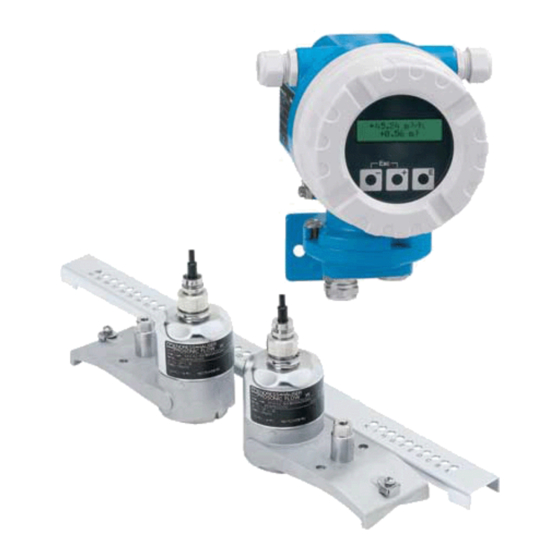
Proline Prosonic Flow 91 Identification Identification Device designation The flowmeter system consists of the following components: • Transmitter Prosonic Flow 91 • Prosonic Flow W sensor 2.1.1 Nameplate of the transmitter Prosonic Flow 91 IP67 / NEMA/Type4X XXXXX-XXXXXXXXXXXX Order Code: 12345678901 Ser.No.:... -
Page 8: Nameplate Of The Sensor
Identification Proline Prosonic Flow 91 2.1.2 Nameplate of the sensor Prosonic Flow W XXXXX-XXXXXXXXXXXX Order Code: 12345678901 RY Ser.No.: W-CL-1F-M-B Type: CH 1 DN100 - DN4000 0°C(+32°F)…+130°C(+266°F) OPEN CLOSE IP68 NEMA N12895 TYPE 6P Tamb/Tumg:-20°…+60°C a0005874 Fig. 2: Nameplate specifications for the "Prosonic Flow W" sensors (example) Ordering code/serial number: See the specifications on the order confirmation for the meanings of the individual letters and digits. -
Page 9: Certificates And Approvals
EMC requirements of IEC/EN 61326. The measuring system described in these Operating Instructions therefore complies with the legal requirements of the EU Directives. Endress+Hauser confirms this by affixing the CE mark to it and by issuing the CE Declaration of Conformity. -
Page 10: Installation
Installation Proline Prosonic Flow 91 Installation Incoming acceptance, transport and storage 3.1.1 Incoming acceptance On receipt of the goods, check the following points: • Check the packaging and the contents for damage. • Check the shipment, make sure nothing is missing and that the scope of supply matches your order. -
Page 11: Installation Conditions
Proline Prosonic Flow 91 Installation Installation conditions 3.2.1 Installation dimensions The dimensions and lengths of the sensor and transmitter can be found in the "Technical Information" document for the device in question. This can be downloaded as a PDF file from www.endress.com. -
Page 12: Orientation
Installation Proline Prosonic Flow 91 3.2.3 Orientation Vertical orientation Recommended orientation with upward direction of flow (View A). Entrained solids sink down. Gases rise away from the measuring sensor when fluid is not flowing. The piping can be completely drained and protected against buildup. -
Page 13: Sensor Selection And Arrangement
Proline Prosonic Flow 91 Installation 3.2.5 Sensor selection and arrangement The sensors can be arranged differently: • Mounting arrangement for measurement via one traverse: the sensors are located on opposite sides of the pipe. • Mounting arrangement for measurement via two traverses: the sensors are located on the same side of the pipe. -
Page 14: Installation Instructions
Installation Proline Prosonic Flow 91 Installation instructions Note! Sensor orientation shown in the following sketches is for visual prupose only. Please apply the recommended sensor orientation → ä 12 3.3.1 Installing tensioning bands For sensor W - DN 50 to 200 (2" to 8") Outer diameter: 62.7 to 220 mm (2.5"... -
Page 15: Installation For Measurement
Proline Prosonic Flow 91 Installation Interlock both halves of the lock (3). Make sure that there is sufficient space for the tensioning band to be tightened with the locking screw. Tighten the tensioning band using a screwdriver (4). a0001110 Fig. 10: Tensioning band installation for DN 250 to 4000 (10"... - Page 16 Installation Proline Prosonic Flow 91 With the first measuring wire: – Fit the fixer over the mounting bolt of the strapping band that is already securely mounted. – Run the measuring wire clockwise around the pipe. – Fit the cable lug over the mounting bolt of the strapping band that can still be moved.
- Page 17 Proline Prosonic Flow 91 Installation Coat the contact surfaces of the sensors with an even layer of coupling fluid approx. 1 mm thick, going from the groove through the center to the opposite edge. A0011373 Fig. 14: Coating the contact surfaces of the sensor with coupling fluid Insert the sensor into the sensor holder.
-
Page 18: Via Two Traverses
Installation Proline Prosonic Flow 91 3.3.3 Installation for measurement via two traverses Prerequisites • The installation distances (sensor distance and wire length) are known → ä 12. • The strapping bands are already mounted → ä 14. Material The following material is needed for mounting: •... - Page 19 Proline Prosonic Flow 91 Installation Fit the sensor holders over the individual mounting bolts and tighten securely with the retaining nut. A0001117 Fig. 17: Mounting the sensor holders Coat the contact surfaces of the sensors with an even layer of coupling fluid approx. 1 mm thick, going from the groove through the center to the opposite edge.
-
Page 20: Affixing The Local Display To The
Installation Proline Prosonic Flow 91 3.3.4 Affixing the local display to the blind version A local display can be temporarily affixed to devices which do not have a local display. Switch off power supply. Remove the cover of the electronics compartment. -
Page 21: Mounting The Transmitter
Proline Prosonic Flow 91 Installation 3.3.6 Mounting the transmitter The transmitter can be mounted in the following ways: • Wall mounting • Pipe mounting (with separate mounting kit, accessories → ä 46) " Caution! • The ambient temperature range (–25 to +60 °C; –13 to +140 °F) may not be exceeded at the mounting location. -
Page 22: Wiring
Wiring Proline Prosonic Flow 91 Wiring Connecting the sensor connecting cables 4.1.1 Connecting Prosonic Flow W Note! The outer shield of the sensor connecting cable (triaxial cable) is grounded by a ground disk in the cable feedthrough (A). This grounding is absolutely essential to ensure correct measurement. -
Page 23: Cable Specifications
4.1.2 Cable specifications Sensor cable • Use the ready-to-use cables supplied by Endress+Hauser with each sensor pair. • The following cable lengths are available: – 5 m, 10 m, 15 m , 30 m, 60 m – 16 ft, 33 ft, 49 ft, 98 ft, 197 ft •... -
Page 24: Connecting The Measuring Unit
Wiring Proline Prosonic Flow 91 Connecting the measuring unit 4.2.1 Transmitter Warning! • Risk of electric shock. Switch off the power supply before opening the device. Do not install or wire the device while it is connected to the power supply. Failure to comply with this precaution can result in irreparable damage to the electronics. -
Page 25: Terminal Assignment
Proline Prosonic Flow 91 Wiring 4.2.2 Terminal assignment Terminal No. (wiring diagram → å 24) 24 (+) 25 (–) 26 (+) 27 (–) 1 (L1/L+) 2 (N/L–) Pulse output HART current output Power supply Note! Functional values of the outputs and power supply → ä 61 4.2.3... -
Page 26: Potential Equalization
IP 67/68 protection is maintained: • Only use cables supplied by Endress+Hauser with the corresponding sensor connectors. • The cable connector seals (1) must be clean, dry and undamaged when inserted in the seal groove. -
Page 27: Post-Connection Check
Proline Prosonic Flow 91 Wiring Post-connection check Perform the following checks after completing electrical installation of the measuring device: Device condition and specifications Notes Are cables or the device damaged (visual inspection)? Electrical connection Notes Does the supply voltage match the specifications on the nameplate? •... -
Page 28: Operation
Operation Proline Prosonic Flow 91 Operation Display and operating elements The configured measured variables are indicated on the local display. Diagnosis messages can appear during commissioning or in the event of a certain malfunction in operation. The diagnosis message is indicated on the display, alternating with the configured measured variable. -
Page 29: Brief Guide To The Function Matrix
Proline Prosonic Flow 91 Operation Brief guide to the function matrix Note! • Please refer to the general notes on → ä 30. • Function matrix overview → ä 67 • Detailed description of all functions → ä 69 The function matrix is a two-level construct: the function groups form one level and the groups' functions the other. -
Page 30: General Notes
• If programming is disabled and the P operating elements are pressed in any function, a prompt for the code automatically appears on the display. • If "0" is specified as the private code, programming is always enabled. • The Endress+Hauser service organization can be of assistance if the personal code is lost. " Caution! Changing certain sensor specific parameters may influence characteristics of numerous functions of the entire measuring device, particularly measuring accuracy. -
Page 31: Communication
Communicator contains more detailed information on the device. Operating program "FieldCare" FieldCare is Endress+Hauser’s FDT-based plant asset management tool and allows the configuration and diagnosis of intelligent field devices. By using status information, you also have a simple but effective tool for monitoring devices. The Proline flowmeters are accessed via a service interface or via the service interface FXA291. -
Page 32: Device Description Files For Operating Programs
The Fieldcheck tester/simulator is used for testing flowmeters in the field. When used in conjunction with the "FieldCare" software package, test results can be imported into a database, printed and used for official certification. Contact your Endress+Hauser representative for more information. -
Page 33: Hart Commands
Proline Prosonic Flow 91 Operation 5.3.4 Universal / common practice HART commands The following table contains all the universal commands supported by the device. Command No. Command data Response data HART command / Access type (numeric data in decimal form) - Page 34 Operation Proline Prosonic Flow 91 Command No. Command data Response data HART command / Access type (numeric data in decimal form) (numeric data in decimal form) Set HART shortform address Byte 0: desired address (0 to 15) Byte 0: active address...
- Page 35 Proline Prosonic Flow 91 Operation Command No. Command data Response data HART command / Access type (numeric data in decimal form) (numeric data in decimal form) Read output information of none – Byte 0: alarm selection ID primary process variable –...
- Page 36 Operation Proline Prosonic Flow 91 The following table contains all the common practice commands supported by the device. Command No. Command data Response data HART command / Access type (numeric data in decimal form) (numeric data in decimal form) Common practice commands...
- Page 37 Proline Prosonic Flow 91 Operation Command No. Command data Response data HART command / Access type (numeric data in decimal form) (numeric data in decimal form) Read assignment of the device none Display of the current variable assignment of the...
-
Page 38: Device Status/Diagnosis Messages
Operation Proline Prosonic Flow 91 5.3.5 Device status/diagnosis messages You can read the extended device status, in this case, current diagnosis messages, via Command "48". The command delivers bit-encoded information (see table below). Note! • For detailed information on the device status/diagnosis messages and how they are rectified →... -
Page 39: Commissioning
Proline Prosonic Flow 91 Commissioning Commissioning Function check Make sure that all final checks have been completed before you commission your measuring point: • "Post-installation check" checklist → ä 21 • "Post-connection check" checklist → ä 27 Switching on the measuring device Once the post-connection checks have been successfully completed, it is time to switch on the supply voltage. -
Page 40: Commissioning Via A Configuration Program
Commissioning Proline Prosonic Flow 91 Commissioning via a configuration program Sensor Setup/sensor installation 6.3.1 For sensor installation with the configuration program "FieldCare" any "Quick Setup" menus which correspond to the local operation exist. Other methods (see table) are available for determining the relevant values for sensor distance, wire length, etc. -
Page 41: Commissioning
Proline Prosonic Flow 91 Commissioning "Clamp-on" sensor installation Procedure Local display (Sensor Setup) ▼ Selection - Input - display Cable length CABLE LENGTH Display sensor position POSITION SENSOR (for sensor installation) Display wire length WIRE LENGTH (for sensor installation) Display sensor distance... -
Page 42: Data Backup/Transmission
Commissioning Proline Prosonic Flow 91 6.3.3 Data backup/transmission Using the T-DAT SAVE/LOAD function (→ ä 74), you can transfer data (device parameters and settings) between the T-DAT (exchangeable memory) and the EEPROM (device storage unit). This is required in the following instances: •... -
Page 43: Application Specific Commissioning
In instances of this nature, please contact your Endress+Hauser service center. • You can view the currently valid zero point value using the "ZERO POINT" function (→ ä 95). -
Page 44: Data Storage Devices
– Repeatedly press and release the Esc key (X). Data storage devices At Endress+Hauser, the term HistoROM refers to various types of data storage modules on which process and measuring device data are stored. By plugging and unplugging such modules, device configurations can be duplicated onto other measuring devices to cite just one example. -
Page 45: Maintenance
Proline Prosonic Flow 91 Maintenance Maintenance No special maintenance work is required. Exterior cleaning When cleaning the exterior of measuring devices, always use cleaning agents that do not attack the surface of the housing and the seals. Coupling fluid A coupling fluid is required to ensure the acoustic link between the sensor and the piping. This is applied to the sensor surface during commissioning. -
Page 46: Accessories
Accessories Proline Prosonic Flow 91 Accessories Various accessories, which can be ordered separately from Endress+Hauser, are available for the transmitter and the sensor. Your Endress+Hauser service organization can provide detailed information on the order code in question. Device-specific accessories Accessory... -
Page 47: Communication-Specific Accessories
Handheld terminal for remote configuration and for obtaining SFX100 – ******* Field Xpert SFX 100 measured values via the 4 to 20 mA HART current output. Contact your Endress+Hauser representative for more information. Fieldgate FXA320 Gateway for remote interrogation of HART sensors and FXA320 –... -
Page 48: Service-Specific Accessories
Software for selecting and configuring flowmeters. DXA80 – * Applicator can be downloaded from the Internet or ordered on CD-ROM for installation on a local PC. Contact your Endress+Hauser representative for more information. Fieldcheck Tester/simulator for testing flowmeters in the field. -
Page 49: Troubleshooting
Proline Prosonic Flow 91 Troubleshooting Troubleshooting Troubleshooting instructions Always start troubleshooting with the checklist below, if faults occur after startup or during operation. This takes you directly (via various queries) to the cause of the problem and the appropriate remedial measures. -
Page 50: Diagnosis Code Messages
Troubleshooting Proline Prosonic Flow 91 Diagnosis code messages 9.2.1 Category F diagnosis code messages Code on Cause Remedy Device behavior: (Spare parts → ä 55) local display factory setting ( ) = options F 001 Serious device error Replace the amplifier board. -
Page 51: Category C Diagnosis Code Messages
Proline Prosonic Flow 91 Troubleshooting 9.2.2 Category C diagnosis code messages Code on Cause Remedy Device behavior: (Spare parts → ä 55) local display factory setting ( ) = options C 281 Initialization is running. Wait until the procedure is finished. -
Page 52: Category S Diagnosis Code Messages
Troubleshooting Proline Prosonic Flow 91 9.2.3 Category S diagnosis code messages Code on Cause Remedy Device behavior: (Spare parts → ä 55) local display factory setting ( ) = options S 437 The sound velocity is outside the search – Check the installation dimensions. -
Page 53: Process Errors Without Messages
The following options are available for tackling problems of this nature: other fault not described above has Request the services of an Endress+Hauser service technician occurred. If you contact our service organization to have a service technician sent out, please be ready with the following... -
Page 54: Response Of Outputs To Errors
Troubleshooting Proline Prosonic Flow 91 Response of outputs to errors Note! The response of the totalizer, current output, pulse output and status output is defined in the FAILSAFE MODE function (→ ä 99). The outputs can be set to their fallback value be means of the postitive zero return. Applicable when operation has to be interrupted while a pipe is being cleaned. -
Page 55: Spare Parts
Note! You can order spare parts directly from your Endress+Hauser service organization by quoting the serial number printed on the transmitter nameplate → ä 7. Spare parts are shipped as sets comprising the following parts: •... -
Page 56: Removing And Installing Electronics Boards
Troubleshooting Proline Prosonic Flow 91 Removing and installing electronics boards 9.6.1 Field housing: removing and installing electronics boards → å 35 Warning! • Risk of electric shock. Exposed components carry dangerous voltages. Make sure that the power supply is switched off before you remove the cover of the electronics compartment. - Page 57 Proline Prosonic Flow 91 Troubleshooting a0005831 Fig. 35: Field housing: removing and installing electronics boards Local display Latches Connectors for sensor cable Connector for power supply Connector for current output and pulse/status output Connector of local display Securing screws of the board carrier...
-
Page 58: Replacing The Device Fuse
Troubleshooting Proline Prosonic Flow 91 Replacing the device fuse Warning! Risk of electric shock. Exposed components carry dangerous voltages. Make sure that the power supply is switched off before you remove the cover of the electronics compartment. The device fuse is located on the electronics board (→ å 36). -
Page 59: Return
Costs incurred for waste disposal and injury (burns, etc.) due to inadequate cleaning will be charged to the owner-operator. The following steps must be taken before returning a flow measuring device to Endress+Hauser, e.g. for repair or calibration: • Always enclose a duly completed "Declaration of contamination" form. Only then can Endress+Hauser transport, examine and repair a returned device. -
Page 60: Technical Data
Technical data Proline Prosonic Flow 91 Technical data 10.1 Technical data at a glance 10.1.1 Application • Measuring the flow rate of fluids in closed piping systems. • Applications in measuring, control and regulation technology for monitoring processes. 10.1.2 Function and system design Measuring principle Prosonic Flow operates on the principle of transit time difference. -
Page 61: Output
Proline Prosonic Flow 91 Technical data 10.1.4 Output Output signal Current output • Galvanically isolated • Full scale value adjustable • Temperature coefficient: typ. 2 μA/°C, resolution: 1.5 μA Ω (for HART: RL ≥ 250 Ω) • Active: 4 to 20 mA, R <... -
Page 62: Performance Characteristics
Technical data Proline Prosonic Flow 91 10.1.6 Performance characteristics Reference operating • Fluid temperature: +28 °C ± 2 K conditions • Ambient temperature: +22 °C ± 2 K • Warm-up period: 30 minutes Installation: • Inlet run >10 × DN •... -
Page 63: Operating Conditions: Installation
Proline Prosonic Flow 91 Technical data Verification of Measurement Uncertainty If required, the device can be supplied with a verification of measurement uncertainty (measurement report). To certify the uncertainty of the device, a measurement is performed under reference conditions. Here, the sensors are mounted on a pipe with a nominal diameter of DN 100. -
Page 64: Operating Conditions: Environment
Technical data Proline Prosonic Flow 91 10.1.8 Operating conditions: Environment Ambient temperature range Transmitter –25 to +60 °C (–13 to +140 °F) Optional: –40 to +60 °C (–40 to +140 °F) At ambient temperatures below –20 °C (–4 °F) the readability of the display may be impaired. -
Page 65: Mechanical Construction
Proline Prosonic Flow 91 Technical data 10.1.10 Mechanical construction Design, dimensions The dimensions and lengths of the sensor and transmitter can be found in the "Technical Information" document for the device in question. This can be downloaded as a PDF file from www.endress.com. -
Page 66: Certificates And Approvals
10.1.12 Certificates and approvals Ex approval Information about currently available Ex versions (FM, CSA) can be supplied by your Endress+Hauser Sales Center on request. All explosion protection data are given in a separate documentation which is available upon request. CE mark The measuring system is in conformity with the statutory requirements of the EC Directives. -
Page 67: Description Of Device Functions
Proline Prosonic Flow 91 Description of device functions Description of device functions 11.1 Illustration of the function matrix Endress+Hauser... - Page 68 Description of device functions Proline Prosonic Flow 91 Endress+Hauser...
-
Page 69: Group Measuring Values
Proline Prosonic Flow 91 Description of device functions 11.2 Group MEASURING VALUES Functional description MEASURING VALUES Note! • The engineering unit of the measured variable displayed here can be set in the SYSTEM UNITS group, (→ ä 71). • If the fluid in the pipe flows backwards, a negative sign prefixes the flow reading on the display. -
Page 70: Group Sensor Setup
Description of device functions Proline Prosonic Flow 91 11.3 Group SENSOR SETUP Functional description SENSOR SETUP SETUP Picklist SENSOR SETUP: • SETUP • LIQUID • PIPE DATA • LINER • CONFIG. CHANNEL • POS. SENSOR • QUIT SETUP: LIQUID → TEMPERATURE → SOUND VEL. LIQUID →... -
Page 71: Group System Units
Proline Prosonic Flow 91 Description of device functions 11.4 Group SYSTEM UNITS Functional description SYSTEM UNITS Use this function group to select the unit required and displayed for the measured variable. UNIT VOLUME FLOW Use this function to select the unit for displaying the volume flow. - Page 72 Description of device functions Proline Prosonic Flow 91 Functional description SYSTEM UNITS UNIT Use this function to select the unit for the liquid temperature. TEMPERATURE Note! The liquid temperature is entered in the function TEMPERATURE (→ ä 90). Options: °C (Celsius) K (Kelvin) °F (Fahrenheit)
-
Page 73: Group Operation
HOME position. • You can also disable programming in this function by entering any number (other than the defined private code). • The Endress+Hauser service organization can be of assistance if you mislay your personal code. DEF.PRIVATE CODE Use this function to enter a personal code to enable programming. - Page 74 Description of device functions Proline Prosonic Flow 91 Functional description OPERATION T-DAT SAVE/LOAD In this function, the configuration/settings of the transmitter can be saved to a transmitter DAT (T-DAT) or uploading a configuration from the T-DAT to the EEPROM can be activated (manual back-up function).
-
Page 75: Group User Interface
Proline Prosonic Flow 91 Description of device functions 11.6 Group USER INTERFACE Functional description USER INTERFACE FORMAT Use this function to define the maximum number of places after the decimal point displayed for the reading in the main line. Options: XXXXX. -
Page 76: Group Totalizer
Description of device functions Proline Prosonic Flow 91 11.7 Group TOTALIZER Functional description TOTALIZER The total for the totalizer's measured variable aggregated since measuring commenced appears on the display. This value can be positive or negative, depending on: • Flow direction and/or •... -
Page 77: Group Current Output
Proline Prosonic Flow 91 Description of device functions 11.8 Group CURRENT OUTPUT Functional description CURRENT OUTPUT Note! The functions of the CURRENT OUTPUT group are only available if the "0" value was entered in the BUS ADDRESS function → ä 84. - Page 78 Description of device functions Proline Prosonic Flow 91 Functional description CURRENT OUTPUT VALUE 20 mA Use this function to assign the 20 mA current a full scale value. Positive and negative values are permissible. The required measuring range is defined by defining the VALUE 20 mA .
-
Page 79: Group Pulse/Status Output
Proline Prosonic Flow 91 Description of device functions 11.9 Group PULSE/STATUS OUTPUT Functional description PULSE/STATUS OUTPUT OPERATION MODE Configuration of the output as a pulse or status output. The functions available in this function group vary, depending on which option you select here. - Page 80 Description of device functions Proline Prosonic Flow 91 Functional description PULSE/STATUS OUTPUT OUTPUT SIGNAL Note! This function is not available unless the PULSE setting was selected in the OPERATING MODE function. Use this function to configure the output in such a way that it matches an external counter, for example.
- Page 81 Proline Prosonic Flow 91 Description of device functions Functional description PULSE/STATUS OUTPUT SWITCH-OFF POINT Note! This function is not available unless LIMIT VALUE was selected in the ASSIGN STATUS OUTPUT function. Use this function to assign a value to the switch-off point (status output drops off).
-
Page 82: Information On The Response Of The Status Output
Description of device functions Proline Prosonic Flow 91 11.9.1 Information on the response of the status output General If you have configured the status output for "LIMIT VALUE" or "FLOW DIRECTION", you can configure the requisite switch points in the SWITCH-ON POINT and SWITCH-OFF POINT functions. -
Page 83: Switching Behavior Of The Status Output
Proline Prosonic Flow 91 Description of device functions 11.9.2 Switching behavior of the status output Function Status Open collector behavior (Transistor) ON (operation) System in measuring mode conductive XXX.XXX.XX A0001237 System not in measuring mode not conductive XXX.XXX.XX (power supply failed) -
Page 84: Group Communication
MANUFACTURER ID Use this function to view the manufacturer number in decimal numerical format. Display: – Endress+Hauser – 17 (≅ 11 hex) for Endress+Hauser DEVICE ID Use this function to view the device ID in hexadecimal numerical format. Display: 62 hex (≅ 98 dez) for Prosonic Flow 91... -
Page 85: Group Process Parameter
Proline Prosonic Flow 91 Description of device functions 11.11 Group PROCESS PARAMETER Functional description PROCESS PARAMETER ON-VALUE LOW Use this function to enter the switch-on point for low flow cut off. FLOW CUT OFF Low flow cut off is active if the value entered is not equal to 0. The sign of the flow value is highlighted on the display to indicate that low flow cut off is active. - Page 86 Description of device functions Proline Prosonic Flow 91 Functional description PROCESS PARAMETER ZERO POINT Use this function to start zero point adjustment automatically. The new zero point ADJUSTMENT determined by the measuring system is adopted by the ZERO POINT function.
-
Page 87: Group Pipe Data
Proline Prosonic Flow 91 Description of device functions 11.12 Group PIPE DATA Functional description PIPE DATA PIPE MATERIAL Use this function to display the pipe material. This is specified by the option selected in the function PIPE STANDARD. If you edit the predetermined value, the pipe standard will be reset to the option OTHER and the function NOMINAL DIAMETER does not appear. - Page 88 Description of device functions Proline Prosonic Flow 91 Functional description PIPE DATA WALL THICKNESS Use this function to display the wall thickness of the pipe. The wall thickness must be entered. User input: Fixed point number 0.1 to max. 1000 mm (depends on nominal diameter) Factory setting: 3.2 mm...
-
Page 89: Group Liner
Proline Prosonic Flow 91 Description of device functions 11.13 Group LINER Functional description LINER LINER MATERIAL Use this function to display the liner material of the pipe. The liner material must be specified if a liner is present. Options: LINER NONE... -
Page 90: Group Liquid Data
Description of device functions Proline Prosonic Flow 91 11.14 Group LIQUID DATA Functional description LIQUID DATA LIQUID Use this function to select the liquid in the pipe. Options: WATER SEA WATER DISTILLED WATER AMMONIA ALCOHOL BENZENE BROMIDE ETHANOL GLYCOL KEROSENE... - Page 91 Proline Prosonic Flow 91 Description of device functions Functional description LIQUID DATA SOUND VELOCITY Use this function to display the sound velocity of the liquid. This is determined via the LIQUID values of the functions LIQUID and TEMPERATURE. If you edit the predetermined value, the function LIQUID will be reset to the option OTHER.
- Page 92 Description of device functions Proline Prosonic Flow 91 Functional description LIQUID DATA SOUND VELOCITY Use this function to specify the upper search range for the sound velocity of the liquid. POSITIVE User input: Fixed-point number 0 to 1000 m/s Factory setting:...
-
Page 93: Group Config. Channel
Proline Prosonic Flow 91 Description of device functions 11.15 Group CONFIG. CHANNEL Functional description CONFIG. CHANNEL SENSOR TYPE Options: W-CL-1F-L-B W-CL-2F-L-B W-CL-1F-L-C W-CL-05F-L-B W-CL-1F-M-B W-CL-2F-M-B Factory setting: W-CL-2F-L-B SENSOR Use this function to select the configuration for the ultrasonic clamp-on sensors. - Page 94 Description of device functions Proline Prosonic Flow 91 Functional description CONFIG. CHANNEL POSITION SENSOR Use this function to view the position of both sensors on the rail. Display: 4-digit number combination Note! This function is only available if the number of traverses is 2 or 4 (see function SENSOR CONFIGURATION).
-
Page 95: Group Calibration Data
Proline Prosonic Flow 91 Description of device functions 11.16 Group CALIBRATION DATA Functional description CALIBRATION DATA CAL. FACTOR Use this function to call up the calibration factor currently used. Data indicated: 5-digit floating-point number (typically 1.000) ZERO POINT Use this function to call up the zero point correction currently used. -
Page 96: Group System Parameter
Description of device functions Proline Prosonic Flow 91 11.17 Group SYSTEM PARAMETER Functional description SYSTEM PARAMETER ISTALLATION Use this function to reverse the sign of the flow quantity, if necessary. DIRECTION SENSOR Options: FORWARDS (flow as indicated by the arrow) - Page 97 Proline Prosonic Flow 91 Description of device functions Functional description SYSTEM PARAMETER MEASURING MODE Pulse output (Contd) STANDARD Only flow components of the positive flow direction are output. Components in the opposite direction are not taken into account. SYMMETRY The absolute value of the positive and negative flow components is taken into account.
- Page 98 Description of device functions Proline Prosonic Flow 91 Functional description SYSTEM PARAMETER POSITIVE ZERO Use this function to interrupt evaluation of measured variables. RETURN This is necessary when a piping system is being cleaned, for example. This setting acts on all function and outputs of the measuring device.
-
Page 99: Group Supervision
Proline Prosonic Flow 91 Description of device functions 11.18 Group SUPERVISION Functional description SUPERVISION FAILSAFE MODE The dictates of safety render it advisable to ensure that the device signal processing assumes a predefined state in the event of an alarm. The setting you select here is valid for: •... - Page 100 Description of device functions Proline Prosonic Flow 91 Functional description SUPERVISION ALARM DELAY Use this function to define a time span in which the criteria for an error have to be satisfied without interruption before an error or notice message is generated.
-
Page 101: Group Simulation System
Proline Prosonic Flow 91 Description of device functions 11.19 Group SIMULATION SYSTEM Functional description SIMULATION SYSTEM SIMULATION Use this function to set all outputs and the totalizer to their defined failsafe modes, in order FAILSAFE MODE to check whether they respond correctly. -
Page 102: Group Sensor Version
Description of device functions Proline Prosonic Flow 91 11.20 Group SENSOR VERSION Functional description SENSOR VERSION SERIAL NUMBER Use this function to view the serial number of the measuring system. 11.21 Group AMPLIFIER VERSION Functional description AMPLIFIER VERSION SOFTWARE REVISION Use this function to view the software revision number of the electronics board. -
Page 103: Factory Settings
Proline Prosonic Flow 91 Description of device functions 11.22 Factory settings 11.22.1 SI units Parameter Factory setting Nominal diameter 80 [mm] Low flow (v ≈ 0.04 m/s) 12 [l/min] Full scale value (v ≈ 2.5 m/s) 750 [l/min] Pulse value 5.0 [l]... -
Page 104: Index
Proline Prosonic Flow 91 Index Index Documentation....... . . 66 ACCESS CODE . - Page 105 Proline Prosonic Flow 91 Index AMS (Emerson Process Management)... 12, 31 Device description files......32 Incoming acceptance.
- Page 106 Proline Prosonic Flow 91 Index SENSOR TYPE ....... . . 93 Sensors (installation) VALUE 20 mA .
- Page 107 Declaration of Contamination Erklärung zur Kontamination Because of legal regulations and for the safety of our employees and operating equipment, we need the "declaration of contamination", with your signature, before your order can be handled. Please make absolutely sure to include it with the shipping documents, or - even better - attach it to the outside of the packaging.
- Page 108 www.endress.com/worldwide BA100D/06/en/02.10 71109049 FM+SGML6.0 ProMoDo...
Need help?
Do you have a question about the Proline Prosonic Flow 91 and is the answer not in the manual?
Questions and answers