Table of Contents
Advertisement
Quick Links
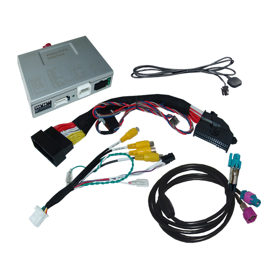
Compatible with Ford vehicles with
Sync3 full version with APIM
7inch or 8inch, tablet or non-tablet monitor.
Video-inserter for front- and rear-view camera
Product features
Video-inserter for factory-infotainment systems
1 CVBS Input for rear-view camera
1 CVBS Input for front camera
2 CVBS video-inputs for after-market devices (e.g. USB-Player, DVB-T2 tuner)
Automatic switching to rear-view camera input on engagement of the reverse gear
Automatic front camera switching after reverse gear for 10 seconds
Activatable parking guide lines for rear-view camera (not available for all vehicles)
Video-in-motion (ONLY for connected video-sources)
Video-inputs NTSC and PAL compatible
Version 26.01.2022
Video-inserter
CI-RL4-SY3
and two additional video sources
HW: CAM(100)/(V20/Y+V41)
CI-RL4-SY3
Advertisement
Table of Contents

Related Manuals for NavLinkz r.LiNK CI-RL4-SY3


Summary of Contents for NavLinkz r.LiNK CI-RL4-SY3
- Page 1 Video-inserter CI-RL4-SY3 Compatible with Ford vehicles with Sync3 full version with APIM 7inch or 8inch, tablet or non-tablet monitor. Video-inserter for front- and rear-view camera and two additional video sources Product features Video-inserter for factory-infotainment systems 1 CVBS Input for rear-view camera ...
-
Page 2: Table Of Contents
Contents Prior to installation 1.1. Delivery contents 1.2. Checking the compatibility of vehicle and accessories 1.3. Connectors – video interface 1.4. Dip switch settings 1.4.1. 8 dip – black 1.4.1.1. Activating the front camera input (dip 1) 1.4.1.2. Enabling the interface’s video inputs (dip 2-3) 1.4.1.3. -
Page 3: Prior To Installation
Legal Information By law, watching moving pictures while driving is prohibited, the driver must not be distracted. We do not accept any liability for material damage or personal injury resulting, directly or indirectly, from installation or operation of this product. Apart from using this product in an unmoved vehicle, it should only be used to display fixed menus or rear-view- camera video when the vehicle is moving (for example the MP3 menu for DVD upgrades). -
Page 4: Checking The Compatibility Of Vehicle And Accessories
1.2. Checking the compatibility of vehicle and accessories Compatibility Brand Compatible vehicles Infotainment systems C-Max since model year 2018 Ecosport since model year 2017 Sync3 full version with APIM and Fiesta since model year 2018 since 07/2017 with 7inch or 8inch tablet or non- Focus since model year 2017 table monitor –... -
Page 5: Connectors - Video Interface
1.3. Connectors – video interface The video-interface converts the video signals of connected after-market sources in a factory monitor compatible picture signal which is inserted in the factory monitor, by using separate trigger options. Further it reads the vehicle’s digital signals out of the vehicle’s CAN-bus and converts them for the video interface. -
Page 6: Dip Switch Settings
1.4. Dip-switch settings 1.4.1. 8 dip - black Some settings have to be selected by the dip-switches on the video interface. Dip position down is ON and position up is OFF. Function ON (down) OFF (up) Front camera enabled* disabled Power supply +12V (max. -
Page 7: Activating The Front Camera Input (Dip 1)
1.4.1.1. Activating the front camera input (dip 1) If set to ON, the interface switches for 10 seconds from the rear-view camera to the front camera input after having disengaged the reverse gear. In addition, a manual switch-over to the front camera input is possible via keypad (short press) from any image mode. Description of the power supply output: see chapter “Power supply output”. -
Page 8: Dip - Red
1.4.2. 4 dip - red By using the Dip-switches, the factory Head-unit or vehicle can be chosen which the interface will be connected to. Dip position down is ON and position up is OFF. Vehicle/Navigation Dip 1 Dip 2 Dip 3 Dip 4 Ford Sync 3 light (R5) ON... -
Page 9: Connection Schema
2.2. Connection schema Version 26.01.2022 HW: CAM(100)/(V20/Y+V41) CI-RL4-SY3... -
Page 10: Connection - Sync3 Full Version As All-In-One Head-Unit
2.3. Connection – Sync3 full version as ALL-IN-ONE head-unit Place of Installation is behind the head unit - with the ALL-IN-ONE head unit, the APIM module is attached as a sandwich to the back of the monitor. Note: The radio module is a separate DIN-sized module and is NOT required for installation! No liability for vehicle wire colours and pin definition! Changes by the vehicle manufacturer are possible. -
Page 11: Connection Picture Signal Cable
2.3.1. Connection picture signal cable Connect the female picture signal cable’s WATERBLUE coloured HSD+2 connector to the male WATERBLUE coloured HSD+2 connector of the video interface. Disconnect the CURRY coloured female 4pin HSD connector of the HSD bridge at the rear side of the monitor and connect it to the male PURPLE coloured HSD connector... -
Page 12: Connection Pnp Power / Can Cable
2.3.2. Connection PNP power / CAN cable Connect the enclosed PNP Power / CAN cable’s female10pin connector to the male 10pin connector of the video interface. Disconnect the female 54pin connector of the vehicle harness at the rear side of the monitor and connect it to the male 54pin connector of the enclosed PNP Power/CAN cable. -
Page 13: Connection - Sync3 Full Version With Tablet Monitor And Separate Apim Module
2.4. Connection – Sync3 full version with tablet monitor and separate APIM module Place of Installation is behind the monitor and on the APIM module - the APIM module is located behind the centre console or behind the glove box. Note: The radio module is a separate DIN-sized module and is NOT required for installation! No liability for vehicle wire colours and pin definition! Changes by the vehicle manufacturer are possible. -
Page 14: Connection Picture Signal Cable
2.4.1. Connection picture signal cable Connect the female picture signal cable’s WATERBLUE coloured HSD+2 connector to the male WATERBLUE coloured HSD+2 connector of the video interface. Disconnect the CURRY coloured female 4pin HSD connector of the factory harness at the rear side of the monitor and connect it to the male PURPLE coloured HSD connector of the enclosed 4pin HSD LVDS cable. -
Page 15: Connection Pnp Power / Can Cable
2.4.2. Connection PNP power / CAN cable The APIM module is located behind the centre console or behind the glove box. Connect the enclosed PNP Power / CAN cable’s female10pin connector to the male 10pin connector of the video interface. Disconnect the female 54pin connector of the vehicle harness at the rear side of the APIM module and connect it to the male 54pin connector of the enclosed PNP Power/CAN cable. -
Page 16: Special Case: Sync3 Light (R5) Version With 6.5Inch Or 8Inch Tablet Monitor And Radio Module With Hsd + Sync Connected Radio Version With 4Inch Monitor
2.5. Special case: Sync3 Light (R5) version with 6.5inch or 8inch tablet monitor and radio module with HSD + Sync Connected Radio version with 4inch monitor Place of installation: The picture signal cable is connected behind the monitor. The PNP power / CAN cable is connected to the factory radio module (hidden DIN housing). - Page 17 Connect the single grey wire „CAN LOW“ of the 4 cables to the head unit main connector’s white/green cable (bottom/right side) and isolate the connection. Connect the single blue wire „CAN HIGH“ of the 4 cables to the head unit main connector’s green/blue cable (right beside) and isolate the connection.
-
Page 18: Installation With Analogue Connection (Without Can Bus)
2.6. Installation with analogue connection (without CAN bus) If, after connecting the PNP harness, no interface LED lightens up while the ignition is turned on, the interface must also be connected in analogue mode. Connect the female 12pin connector of the 12pin interface cable to the male 12pin connector of the video interface. -
Page 19: Power Supply Output
2.7. Power supply output The red power supply output ACC/front cam out 12V (max 3A) can be used to power an external source and has a different assignment depending on the position of dip switch 1 (of the black 8 dips): Function Dip 1 ON +12V (max. -
Page 20: Connection - Video Sources
3. Connection – Video sources It is possible to connect an after-market rear-view camera, an after-market front camera and two more video sources to the video-interface. Before the final installation, we recommend a test-run to detect a incompatibility of vehicle and interface. Due to changes in the production of the vehicle manufacturer there’s always a possibility of incompatibility. -
Page 21: Audio Insertion
3.1. Audio-insertion This interface is only able to insert video signals into the factory infotainment. If an AV- source is connected, the audio insertion has to be done by the factory audio AUX input or an FM-modulator. The inserted video-signal can be activated simultaneously to each audio- mode of the factory infotainment. -
Page 22: After-Market Rear-View Camera
3.3. After-market rear-view camera Some vehicles have a different reverse gear code on the CAN-bus which doesn’t communicate with the interface’s CAN. In this case there are two different ways of installation. If the interface’s CAN is able to detect an enabled vehicle’s reverse gear, the green wire of the 6pin to 12pin cable should carry +12V while the reverse gear is engaged. -
Page 23: Case 2: Interface Does Not Receive The Reverse Gear Signal
3.3.2. Case 2: Interface does not receive the reverse gear signal If the video interface does not receive +12V on the green wire of the 12pin interface cable when reverse gear is engaged (not all vehicles are compatible), an external switching signal from the reverse gear light is required. - Page 24 3.4. Connection – video-interface and external keypad Connect the keypad’s female 4pin connector to the 12pin interface cable’s male 4pin connector. Note: Even if the switching through several video sources by the keypad mightn’t be required, the keypad’s invisible connection and availability is strongly recommended. Version 26.01.2022 HW: CAM(100)/(V20/Y+V41) CI-RL4-SY3...
-
Page 25: Picture Settings
3.5. Picture settings The picture settings are adjusted by the 3 buttons on the video-interface. Press the MENU button to open the OSD settings menu. To switch to the next menu item, pressing DOWN will change the selected value. The buttons are embedded in the housing to avoid accidental changes during or after installation. -
Page 26: Interface Operation
4. Interface operation 4.1. By Call-Off button Switching the video sources can be done by a long press of the vehicle’s Call-Off button Each press (approx. 2-3sec) will switch to the next enabled input. If all inputs are enabled the order is: ... -
Page 27: Specifications
5. Specifications BATT/ACC range 7V - 25V Stand-by power drain Power consumption 275mA Video input 0.7V - 1V Video input formats NTSC / PAL RGB-video amplitude 0.7V with 75 Ohm impedance Temperature range -40°C to +85°C Dimensions video-box 118 x 25 x 104 mm (W x H x D) Version 26.01.2022 HW: CAM(100)/(V20/Y+V41) CI-RL4-SY3... -
Page 28: Faq - Trouble Shooting-Interface Functions
FAQ – Trouble shooting Interface functions For any troubles which may occur, check the following table for a solution before requesting support from your vendor. Symptom Reason Possible solution Not all connectors have been reconnected to factory head- Connect missing connectors. unit or monitor after installation. - Page 29 Symptom Reason Possible solution Camera input picture Use relay or electronics to "clean" reverse gear lamp black. Camera power taken directly power. Alternatively, if CAN-bus box is compatible Camera input picture from reverse gear lamp. with the vehicle, camera power can be taken from green wire of 6pin to 8pin cable.
Need help?
Do you have a question about the r.LiNK CI-RL4-SY3 and is the answer not in the manual?
Questions and answers