Table of Contents
Advertisement
Quick Links
Video-inserter
CI-VL1-NG4-HU
Compatible with Alfa Romeo Giulietta,
Citroen, Peugeot and Maserati
with navigation NG4 with colour display
and 10pin LVDS monitor connector
Video-inserter with 2 video + rear-view camera input
Product features
Video-inserter for factory-infotainment systems
1 CVBS Rear-view camera video-input
2 CVBS video-inputs for after-market devices (e.g. USB-Player, DVB-T2 tuner, ...)
Automatic switching to rear-view camera input on engagement of reverse gear
Video-in-motion (ONLY for connected video-sources)
AV-inputs PAL/NTSC compatible
Version 14.03.2022
HW 16-(V65)
CI-VL1-NG4-HU
Advertisement
Table of Contents

Subscribe to Our Youtube Channel
Related Manuals for NavLinkz CI-VL1-NG4-HU


Summary of Contents for NavLinkz CI-VL1-NG4-HU
- Page 1 Video-inserter CI-VL1-NG4-HU Compatible with Alfa Romeo Giulietta, Citroen, Peugeot and Maserati with navigation NG4 with colour display and 10pin LVDS monitor connector Video-inserter with 2 video + rear-view camera input Product features Video-inserter for factory-infotainment systems 1 CVBS Rear-view camera video-input ...
-
Page 2: Table Of Contents
Connection – 6pin interface cable 2.4. Connection - head-unit 2.5. Connection - Video-sources 2.5.1. Audio-switch and audio-insertion 2.5.2. After-market rear-view camera 2.6. Connection – external keypad 2.7. Picture settings 3. Interface operation 4. Specifications 5. Frequently asked questions Version 14.03.2022 HW 16-(V65) CI-VL1-NG4-HU... -
Page 3: Prior To Installation
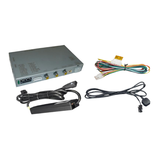
Technical knowledge is necessary for installation. The place of installation must be free of moisture and away from heat sources. 1.1. Delivery contents Take down the serial number of the interface and store this manual for support purposes: ____________________ Version 14.03.2022 HW 16-(V65) CI-VL1-NG4-HU... -
Page 4: Checking The Compatibility Of Vehicle And Accessories
AUDIO audio cable is optionally available for audio switching. Factory rear-view camera Automatic switch-back from inserted video to factory rear-view camera only while reverse gear is engaged. To delay the switch- back time, additional electronics is required. Version 14.03.2022 HW 16-(V65) CI-VL1-NG4-HU... -
Page 5: Connectors - Video Interface
1.3. Connectors – video interface The video-interface converts the connected after-market sources video signals to an LVDS signal which is the inserted into the factory monitor on certain trigger options. Version 14.03.2022 HW 16-(V65) CI-VL1-NG4-HU... -
Page 6: Dip-Switch Settings
4 options, retry and disconnected the 6pin power plug of the video- box between every change of the dip setting. Dip1, 4 and 6 are out of function and have to be set to OFF Version 14.03.2022 HW 16-(V65) CI-VL1-NG4-HU... -
Page 7: Installation
If power source is not taken directly from the battery, the connection has to be checked for being start-up proven and permanent. 2.1. Place of installation The interface is performed to be installed at the rear-side of the head-unit. Version 14.03.2022 HW 16-(V65) CI-VL1-NG4-HU... -
Page 8: Connection Schema
2.2. Connection schema Version 14.03.2022 HW 16-(V65) CI-VL1-NG4-HU... -
Page 9: Connection - 6Pin Interface Cable
Note: The connection of the green wire (Reverse signal) will be described in chapter “After-market rear-view camera”. The white wire, can be used by +12V impulse to switch the enabled video sources , same as the keypad (see chapter “video interface- operation”). Version 14.03.2022 HW 16-(V65) CI-VL1-NG4-HU... -
Page 10: Connection - Head-Unit
Remove female 10pin HSD LVDS connector from the rear of the head-unit and connect it to the LVDS-switch-box of the 10pin HSD LVDS cable. Connect female 10pin connector of the 10pin HSD LVDS cable to the male 10pin HSD LVDS connector of the head-unit. Version 14.03.2022 HW 16-(V65) CI-VL1-NG4-HU... -
Page 11: Connection Video Sources
Connect the rear-view camera’s male RCA to the video interface’s female RCA „Camera IN”. Connect the male RCAs of possibly existing video sources 1 and 2 to the video interface’s female RCAs „Video IN1“ and „Video IN2“. Version 14.03.2022 HW 16-(V65) CI-VL1-NG4-HU... -
Page 12: Audio-Switch And Audio-Insertion
● Blue Audio right Pin 3 ● Brown Ground Pin 5 No liability for vehicle wire colors and pin definition! Possible changes by the vehicle manufacturer. The given information must be verified by the installer. Version 14.03.2022 HW 16-(V65) CI-VL1-NG4-HU... - Page 13 Audio input signal R/L of source AV1 Audio output signal R/L for factory audio AUX or FM-modulator Ground Attention: The audio cable CAB-FV-AUDIO shown in the diagram is not included in the delivery contents and is optionally available! Version 14.03.2022 HW 16-(V65) CI-VL1-NG4-HU...
-
Page 14: After-Market Rear-View Camera
Connect the output connector (87) of the relay to the rear-view camera’s power- cable, like you did it to the green switching input cable before. Connect stabile and permanent +12V to the relay’s input connector (30). Note: Picture settings for CAM input must be done in AV2. Version 14.03.2022 HW 16-(V65) CI-VL1-NG4-HU... -
Page 15: Connection - External Keypad
Note: The OSD menu is only shown when a working video source is connected to the selected video-input of the interface. The following settings are available: Contrast Brightness Saturation Sharpness DVD – no function Tuner – no function Navi – no function Version 14.03.2022 HW 16-(V65) CI-VL1-NG4-HU... -
Page 16: Interface Operation
190mA Video input 0.7V - 1V Video input formats PAL/NTSC RGB-video amplitude 0.7V with 75 Ohm impedance Temperature range -40°C to +85°C Dimensions video-box 158 x 22 x 102 mm (W x H x D) Version 14.03.2022 HW 16-(V65) CI-VL1-NG4-HU... - Page 17 Camera input picture fluorescent light which shines Test camera under natural light outside the garage. flickers. directly into the camera. Camera input picture is Protection sticker not Remove protection sticker from lens. bluish. removed from camera lens. Version 14.03.2022 HW 16-(V65) CI-VL1-NG4-HU...
- Page 18 Cut the grey wire of 6pin to 8pin and isolate both Interface switches compatibility to vehicle is ends. If problem still occurs, additionally cut the white video-sources by itself. limited. wire of 6pin to 8pin cable and isolate both ends. 10R-03 5384 Made in China Version 14.03.2022 HW 16-(V65) CI-VL1-NG4-HU...
Need help?
Do you have a question about the CI-VL1-NG4-HU and is the answer not in the manual?
Questions and answers