Table of Contents
Advertisement
Quick Links
Fiat Ducato 3 (series 8) vehicles
with all in one Uconnect multimedia system
R1LOW with 7inch monitor
Video-inserter for front- and rear-view camera
Product features
• Video-inserter for factory-infotainment systems
• 1 CVBS Input for rear-view camera
• 1 CVBS Input for front camera
• 2 CVBS video-inputs for after-market devices (e.g. USB-Player, DVB-T2 tuner)
• Automatic switching to rear-view camera input on engagement of the reverse gear
• Automatic front camera switching after reverse gear for 10, 15 or 20 seconds
• Video-in-motion (ONLY for connected video-sources)
• Video-inputs NTSC compatible
Version 08.08.2024
Video-inserter
RL4-UCON7-R1L
Compatible with
and two additional video sources
from SW 25 V1.0 / GD V1.0 / GW256 V1.0
RL4-UCON7-R1L
Advertisement
Table of Contents

Related Manuals for NavLinkz RL4-UCON7-R1L


Summary of Contents for NavLinkz RL4-UCON7-R1L
- Page 1 Video-inserter RL4-UCON7-R1L Compatible with Fiat Ducato 3 (series 8) vehicles with all in one Uconnect multimedia system R1LOW with 7inch monitor Video-inserter for front- and rear-view camera and two additional video sources Product features • Video-inserter for factory-infotainment systems • 1 CVBS Input for rear-view camera •...
-
Page 2: Table Of Contents
Case 2: Video interface does not receive the reverse gear signal 2.9. Connection – external keypad Interface operation by external keypad Picture settings Specifications Frequently asked questions Technical support Version 08.08.2024 from SW 25 V1.0 / GD V1.0 / GW256 V1.0 RL4-UCON7-R1L... -
Page 3: Legal Information
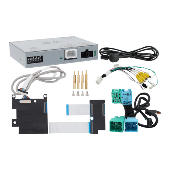
Read the manual prior to installation. Technical knowledge is necessary for installation. The place of installation must be free of moisture and away from heat sources. 1.1. Delivery contents Version 08.08.2024 from SW 25 V1.0 / GD V1.0 / GW256 V1.0 RL4-UCON7-R1L... -
Page 4: Checking The Interface Compatibility Of Vehicle And Accessories
The video-interface converts the video signals of connected after-market sources in a factory monitor compatible picture signal which is inserted in the factory monitor, by using separate trigger options. Version 08.08.2024 from SW 25 V1.0 / GD V1.0 / GW256 V1.0 RL4-UCON7-R1L... -
Page 5: Connectors - Daughter Pcb 1 And
1.3.2. Connectors – daughter PCB 1 and 2 Version 08.08.2024 from SW 25 V1.0 / GD V1.0 / GW256 V1.0 RL4-UCON7-R1L... -
Page 6: Dip-Switch Settings
*The front camera will automatically be switched for 10, 15 or 20 seconds (depending on the setting in the OSD menu) after disengaging the reverse gear. See the following chapters for detailed information. Version 08.08.2024 from SW 25 V1.0 / GD V1.0 / GW256 V1.0 RL4-UCON7-R1L... -
Page 7: Activating The Front Camera Input (Dip 1)
Dip position down is ON and position up is OFF. Set all dip switches to off Vehicle/Navigation Dip 1 Dip 2 Dip 3 Dip 4 All vehicles Version 08.08.2024 from SW 25 V1.0 / GD V1.0 / GW256 V1.0 RL4-UCON7-R1L... -
Page 8: Installation
The daughter PCB 2 is connected to the daughter PCB 1 and installed on the outside of the head unit. The video interface is connected to the daughter PCB 2 and to the back of the head unit. Version 08.08.2024 from SW 25 V1.0 / GD V1.0 / GW256 V1.0 RL4-UCON7-R1L... -
Page 9: Connection Scheme
2.2. Connection Scheme Version 08.08.2024 from SW 25 V1.0 / GD V1.0 / GW256 V1.0 RL4-UCON7-R1L... -
Page 10: Installation - Daughter Pcbs
Installation – daughter PCBs Remove the factory head-unit. The enclosed daughter PCBs has to be installed into the optical lead between the monitor panel and mainboard of the head-unit. Version 08.08.2024 from SW 25 V1.0 / GD V1.0 / GW256 V1.0 RL4-UCON7-R1L... -
Page 11: Warning Notes, Concerning The Installation Of Ribbon Cables
2) The ribbon cable’s contacting side always has to correspond to the contacting side of the connector, concerning the mounting position. Version 08.08.2024 from SW 25 V1.0 / GD V1.0 / GW256 V1.0 RL4-UCON7-R1L... -
Page 12: Connection - Picture Signal Cable
2.4. Connection – picture signal cable Connect the female 20pin connector of the pre-connected 20pin picture signal cable to the male 20pin connector of the video interface. Version 08.08.2024 from SW 25 V1.0 / GD V1.0 / GW256 V1.0 RL4-UCON7-R1L... -
Page 13: Connection - 10Pin Power/Can Cable
Connect the two opposing female green and blue 12- and 32pin sockets of the 10-pin Power/CAN cable to the previously become free male 12- and 32pin connectors of the head unit. Version 08.08.2024 from SW 25 V1.0 / GD V1.0 / GW256 V1.0 RL4-UCON7-R1L... -
Page 14: Analogue Power Supply
Connect the 12pin interface cable’s purple coloured wire Manual ACC to +12V ACC terminal 15 or to +12V S-contact terminal 86s +12V (e.g. glove compartment illumination). Version 08.08.2024 from SW 25 V1.0 / GD V1.0 / GW256 V1.0 RL4-UCON7-R1L... -
Page 15: Power Supply Output
(depending on the setting in the OSD menu) delay after reverse gear is disengaged and +12V by manual switching to front camera by keypad (short press) Dip 1 OFF +12V (max. 3A) ACC Version 08.08.2024 from SW 25 V1.0 / GD V1.0 / GW256 V1.0 RL4-UCON7-R1L... - Page 16 RCA connector „Front V3“. Connect the video RCA of the AV source 1 and 2 to the 12pin interface cable’s female RCA connector “Left (V1)” ”Right (V2)”. Version 08.08.2024 from SW 25 V1.0 / GD V1.0 / GW256 V1.0 RL4-UCON7-R1L...
-
Page 17: Audio Insertion
1 is set to ON and the front camera input is selected). Attention: A long press of the external keypad push button will switch the interface to the next source. Version 08.08.2024 from SW 25 V1.0 / GD V1.0 / GW256 V1.0 RL4-UCON7-R1L... -
Page 18: After-Market Rear-View Camera
20pin cable to avoid an unnecessary, permanent power supply to the camera electronic. For the operation, both green cables “Reverse IN” “Reverse OUT” have to remain onnected. Version 08.08.2024 from SW 25 V1.0 / GD V1.0 / GW256 V1.0 RL4-UCON7-R1L... -
Page 19: Case 2: Video Interface Does Not Receive The Reverse Gear Signal
Connect the output connector (87) of the relay to the rear-view camera’s power- cable, like you did it to the green “Reverse-IN” cable before. Connect permanent power / 12V to the relay’s input connector (30). Version 08.08.2024 from SW 25 V1.0 / GD V1.0 / GW256 V1.0 RL4-UCON7-R1L... -
Page 20: Connection - External Keypad
Connect the keypad’s female 4pin connector to the 12pin interface cable’s male 4pin connector. Note: Even if the switching through several video sources by the keypad mightn’t be required, the keypad’s invisible connection and availability is strongly recommended. Version 08.08.2024 from SW 25 V1.0 / GD V1.0 / GW256 V1.0 RL4-UCON7-R1L... -
Page 21: Interface Operation By External Keypad
➢ Short press of keypad (only if DIP 1 is set to ON) By short pressing the external keypad, the video interfaces switches from the factory video to the front camera input and back to factory video. Version 08.08.2024 from SW 25 V1.0 / GD V1.0 / GW256 V1.0 RL4-UCON7-R1L... -
Page 22: Picture Settings
10, 15 or 20 seconds - 10 seconds is preset) H-SIZE (horizontal picture size) V-SIZE (vertical picture size) Note: To adjust the reverse picture settings, engage the reverse gear. Version 08.08.2024 from SW 25 V1.0 / GD V1.0 / GW256 V1.0 RL4-UCON7-R1L... -
Page 23: Specifications
Dimensions daughter PCB 1 80 x 4 x 37mm (W x H x D) Dimensions daughter PCB 2 105 x 7 x 96mm (W x H x D) Version 08.08.2024 from SW 25 V1.0 / GD V1.0 / GW256 V1.0 RL4-UCON7-R1L... - Page 24 Test camera under natural light outside the garage. flickers. directly into the camera. Camera input picture is Protection sticker not Remove protection sticker from lens. bluish. removed from camera lens. Version 08.08.2024 from SW 25 V1.0 / GD V1.0 / GW256 V1.0 RL4-UCON7-R1L...
-
Page 25: Technical Support
6pin to 8pin cable and isolate both ends. Technical Support Please note that direct technical support is only available for products purchased directly from NavLinkz GmbH. For products bought from other sources, contact your vendor for technical support. NavLinkz GmbH...
Need help?
Do you have a question about the RL4-UCON7-R1L and is the answer not in the manual?
Questions and answers