Table of Contents
Advertisement
Quick Links
Video-inserter
RL4-MBN4
Compatible with
Mercedes Benz
vehicles
with Comand APS HD NTG3, Comand APS NTG4,
Audio20 NTG4 and Audio50 APS NTG4 infotainment
with 10pin LVDS connector at the monitor
Video-inserter for front- and rear-view camera
and two additional video sources
Product features
Video-inserter for factory-infotainment systems
1 CVBS Input for rear-view camera
1 CVBS Input for front camera
2 CVBS Video-inputs for after-market Video sources (e.g. USB-Player, DVB-T Tuner)
Automatic switching to rear-view camera input on engagement of the reverse gear
Automatic front camera switching after reverse gear for 10 seconds
Video-in-motion (ONLY for connected video-sources)
Video-inputs NTSC compatible
Version 15.02.2023
HW CAM (V100) / (EF2L145/V20)
RL4-MBN4
Advertisement
Table of Contents

Subscribe to Our Youtube Channel
Related Manuals for NavLinkz RL4-MBN4


Summary of Contents for NavLinkz RL4-MBN4
- Page 1 Video-inserter RL4-MBN4 Compatible with Mercedes Benz vehicles with Comand APS HD NTG3, Comand APS NTG4, Audio20 NTG4 and Audio50 APS NTG4 infotainment with 10pin LVDS connector at the monitor Video-inserter for front- and rear-view camera and two additional video sources Product features ...
-
Page 2: Table Of Contents
Case 2: Interface does not receive the reverse gear signal 2.8. Connection – external keypad Interface operation by external keypad 3.1. By Comand buttons 3.2. By external keypad Picture settings Specifications Frequently asked questions Technical support Version 15.02.2023 HW CAM (V100) / (EF2L145/V20) RL4-MBN4... -
Page 3: Prior To Installation
Prior to installation Read the manual prior to installation. Technical knowledge is necessary for installation. The place of installation has to be free of moisture and away from heat sources. 1.1. Delivery contents Version 15.02.2023 HW CAM (V100) / (EF2L145/V20) RL4-MBN4... -
Page 4: Checking The Interface Compatibility Of Vehicle And Accessories
The front camera will automatically be switched for 10 seconds after disengaging the reverse gear. A manually front camera switching is possible by external keypad. Video input signal NTSC video sources compatible only. Version 15.02.2023 HW CAM (V100) / (EF2L145/V20) RL4-MBN4... -
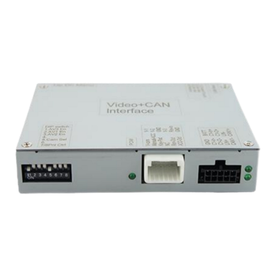
Page 5: Connectors - Video Interface
*The front camera will automatically be switched for 10 seconds after disengaging the reverse gear (see following information). After each Dip-switch-change a power-reset of the Video Interface has to be performed! Version 15.02.2023 HW CAM (V100) / (EF2L145/V20) RL4-MBN4... -
Page 6: Activating The Front Camera Input (Dip 1)
Dip position down is ON and position up is OFF. Set all dip switches to off Vehicle/Navigation Dip 1 Dip 2 Dip 3 Dip 4 All vehicles Version 15.02.2023 HW CAM (V100) / (EF2L145/V20) RL4-MBN4... -
Page 7: Installation
Place of connection The video interface has to be connected on the rear-side of the vehicle’s monitor (picture signal) and on the rear-side of the vehicle’s head-unit (Power and CAN at the Quadlock). Version 15.02.2023 HW CAM (V100) / (EF2L145/V20) RL4-MBN4... -
Page 8: Connection Scheme
2.2. Connection scheme Version 15.02.2023 HW CAM (V100) / (EF2L145/V20) RL4-MBN4... - Page 9 Pay attention to a correct connection of the 10 pins inside! Connect the female 10pin LVDS connector to the previously become free 10pin LVDS connector of the factory monitor Version 15.02.2023 HW CAM (V100) / (EF2L145/V20) RL4-MBN4...
-
Page 10: Connection - 10Pin Power/Can Cable
4 cables to the vehicle’s CAN high wire and isolate the connection Connect the single red wire to stabile +12V terminal Connect the single black cable to the vehicle’s negative Ground. Version 15.02.2023 HW CAM (V100) / (EF2L145/V20) RL4-MBN4... -
Page 11: Special Case - Vehicles With Comand Aps Ntg3 (E.g. W221 S-Klasse)
Connect the single black cable to the vehicle’s negative Ground. No liability for vehicle wire colors and pin definition! Changes by the vehicle manufacturer are possible. The given information must be verified by the installer. Version 15.02.2023 HW CAM (V100) / (EF2L145/V20) RL4-MBN4... -
Page 12: Analogue Power Supply
Connect the female 12pin connector of the 12pin interface cable to the male 12pin connector of the video interface. Connect the 12pin interface cable’s purple coloured wire Manual ACC to +12V Ignition power or to +12V S-contact terminal 86s +12V (e.g. glove compartment illumination). Version 15.02.2023 HW CAM (V100) / (EF2L145/V20) RL4-MBN4... -
Page 13: Power Supply Output
+12V (max. 3A) when reverse gear is engaged plus 10 seconds delay after reverse gear is disengaged and +12V when manually switched to front camera by keypad (short press) Dip 1 OFF +12V permanent (max. 3A) ACC Version 15.02.2023 HW CAM (V100) / (EF2L145/V20) RL4-MBN4... -
Page 14: Connection - Video Sources
Connect the front camera’s video RCA connector to the 12pin interface cable’s female RCA connector „Front V3“. Connect the video RCA of the AV source 1 and 2 to the 12pin interface cable’s female RCA connector “Left (V1)” ”Right (V2)”. Version 15.02.2023 HW CAM (V100) / (EF2L145/V20) RL4-MBN4... -
Page 15: Audio Insertion
(short press) from any image mode. The power supply output gives +12V then, as well (if Dip 1 is set to ON and the front camera input is selected). Attention: A long press of the external keypad push button will switch the interface to the next source. Version 15.02.2023 HW CAM (V100) / (EF2L145/V20) RL4-MBN4... -
Page 16: After-Market Rear-View Camera
The 12 V power supply for the rear-view camera (max 3A) has to be taken from the 12pin interface cabl’s green wire “Reverse-OUT” to avoid an unnecessary, permanent power supply to the camera electronic. Both green cables “Reverse IN” “Reverse OUT” have to remain connected. Version 15.02.2023 HW CAM (V100) / (EF2L145/V20) RL4-MBN4... -
Page 17: Case 2: Interface Does Not Receive The Reverse Gear Signal
Connect the output connector (87) of the relay to the rear-view camera’s power- cable, like you did it to the green “Reverse-IN” cable before. Connect permanent power / 12V to the relay’s input connector (30). Version 15.02.2023 HW CAM (V100) / (EF2L145/V20) RL4-MBN4... -
Page 18: Connection - External Keypad
Connect the keypad’s female 4pin connector to the 12pin interface cable’s male 4pin connector. Note: Even if the switching through several video sources by the keypad mightn’t be required, the keypad’s invisible connection and availability is strongly recommended. Version 15.02.2023 HW CAM (V100) / (EF2L145/V20) RL4-MBN4... -
Page 19: By Comand Buttons
Short press of keypad (only if DIP 1 is set to ON) By short pressing the external keypad, the video interfaces switches from the factory video to the front camera input and back to factory video. Version 15.02.2023 HW CAM (V100) / (EF2L145/V20) RL4-MBN4... -
Page 20: Picture Settings
Video input formats NTSC Temperature range -40°C to +85°C Dimensions Video-box 117 x 26 x 90mm (W x H x D) Dimensions Video switch 125 x 20 x 35mm (W x H x D) Version 15.02.2023 HW CAM (V100) / (EF2L145/V20) RL4-MBN4... - Page 21 Test camera under natural light outside the garage. flickers. directly into the camera. Camera input picture is Protection sticker not Remove protection sticker from lens. bluish. removed from camera lens. Version 15.02.2023 HW CAM (V100) / (EF2L145/V20) RL4-MBN4...
-
Page 22: Technical Support
6pin to 8pin cable and isolate both ends. Technical Support Please note that direct technical support is only available for products purchased directly from NavLinkz GmbH. For products bought from other sources, contact your vendor for technical support. NavLinkz GmbH...
Need help?
Do you have a question about the RL4-MBN4 and is the answer not in the manual?
Questions and answers