Table of Contents
Advertisement
Quick Links
Video-inserter
CI-VL1-CCC
BMW vehicles
with Professional navigation CCC,
Business navigation M-ASK or radio
Monitor sizes: 6.5inch or 8.8inch
Mini vehicles
with Professional navigation CCC infotainment
Monitor size: 6.5inch monitor
Video-inserter with 2 video inputs + rear-view camera input
Product features
Video-inserter for factory-infotainment systems
1 CVBS Rear-view camera video-input
2 CVBS video-inputs for after-market devices (e.g. USB-Player, DVB-T2 tuner, ...)
Automatic switching to rear-view camera input on engagement of the reverse gear
Video-in-motion (ONLY for connected video-sources)
Video-inputs PAL and NTSC compatible
Ultra-wide picture mode 24:9 (only with ultra-wide screen 8.8")
Version 25.02.2022
HW: V65
CI-VL1-CCC
Advertisement
Table of Contents

Related Manuals for NavLinkz CI-VL1-CCC


Summary of Contents for NavLinkz CI-VL1-CCC
- Page 1 Video-inserter CI-VL1-CCC BMW vehicles with Professional navigation CCC, Business navigation M-ASK or radio Monitor sizes: 6.5inch or 8.8inch Mini vehicles with Professional navigation CCC infotainment Monitor size: 6.5inch monitor Video-inserter with 2 video inputs + rear-view camera input Product features ...
-
Page 2: Table Of Contents
Connection – video interface to external keypad 2.9. Picture settings 3. Video interface operation 3.1. By infotainment button 3.2. By external keypad 3.3. By white wire of the 6pin cable 4. Specifications 5. FAQ – Trouble Shooting-Interface functions Version 25.02.2022 HW: V65 CI-VL1-CCC... -
Page 3: Prior To Installation
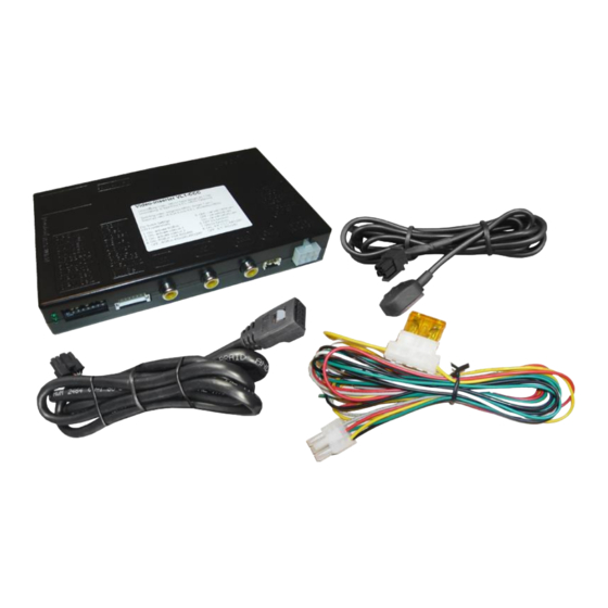
Read the manual prior to installation. Technical knowledge is necessary for installation. The place of installation must be free of moisture and away from heat sources. 1.1. Delivery contents Take down the serial number of the interface and store this manual for support purposes: ____________________ Version 25.02.2022 HW: V65 CI-VL1-CCC... -
Page 4: Checking The Compatibility Of Vehicle And Accessories
To delay the switch-back an additional electronic part is required. Factory-OPS-display While reverse gear is engaged ONLY the picture of the after-market rear-view camera is visible! Ultra-wide mode Only available for ultra-wide screens 8.8” Version 25.02.2022 HW: V65 CI-VL1-CCC... -
Page 5: Connectors - Video Interface
No function set to OFF No function set to OFF Monitor 8.8inchmonitor 6.5inchmonitor adjustments After each Dip-switch-change a power-reset of the Can-box has to be performed! See the following chapters for detailed information. Version 25.02.2022 HW: V65 CI-VL1-CCC... -
Page 6: Enabling The Interface's Video Inputs (Dip 2-3)
Dip switch setting ON will support the 8.8inch monitor. Dip switch setting OFF will support the 6.5inch monitor. Note: Dip 1, 4, 6 and 7 are out of function and have to be set to OFF. Version 25.02.2022 HW: V65 CI-VL1-CCC... -
Page 7: Installation
The interface needs a permanent 12V source! 2.1. Place of installation The interface box is prepared to be connected behind the vehicle`s monitor. The monitor has to be removed for the installation Version 25.02.2022 HW: V65 CI-VL1-CCC... -
Page 8: Connection Schema
2.2. Connection schema Version 25.02.2022 HW: V65 CI-VL1-CCC... -
Page 9: Connection - 6Pin Interface Cable
Note: The connection of the green wire (Reverse signal) will be described in chapter “After-market rear-view camera”. The white wire, can be used by +12V impulse to switch the enabled video sources , same as the keypad (see chapter “video interface- operation”). Version 25.02.2022 HW: V65 CI-VL1-CCC... -
Page 10: Connection - Picture Signal Cable
Connect the enclosed picture signal cable’s female 10 pin connector to the male 10pin connector of the video interface. Connect the picture signal cable’s opposite female 10pin connector to the previously become free male 10pin connector of the video interface. Version 25.02.2022 HW: V65 CI-VL1-CCC... -
Page 11: Connection - Video Sources
Connect the rear-view camera’s male RCA to the video interface’s female RCA „Camera IN”. Connect the male RCAs of possibly existing video sources 1 and 2 to the video interface’s female RCAs „Video IN1“ and „Video IN2“. Version 25.02.2022 HW: V65 CI-VL1-CCC... -
Page 12: Audio-Switch And Audio-Insertion
AUX input). When switching the video interface from AV1 to AV2, the audio signal is also switched automatically. Attention: The audio cable CAB-FV-AUDIO shown in the diagram is not included in the delivery contents and is optionally available! Version 25.02.2022 HW: V65 CI-VL1-CCC... - Page 13 Audio input signal R/L of source AV1 Audio output signal R/L for factory audio AUX or FM-modulator Ground Attention: The audio cable CAB-FV-AUDIO shown in the diagram is not included in the delivery contents and is optionally available! Version 25.02.2022 HW: V65 CI-VL1-CCC...
-
Page 14: After-Market Rear-View Camera
Connect the output connector (87) of the relay to the rear-view camera’s power- cable, like you did it to the green switching input cable before. Connect stabile and permanent +12V to the relay’s input connector (30). Version 25.02.2022 HW: V65 CI-VL1-CCC... -
Page 15: Connection - Video Interface To External Keypad
Connect the keypad’s female 4pin connector to the video-interface’s male 4pin connector. Note: Even if the switching through several video sources by the keypad mightn’t be required, the invisible connection and availability is strongly recommended. Version 25.02.2022 HW: V65 CI-VL1-CCC... -
Page 16: Picture Settings
Note: The OSD menu is only shown when a working video source is connected to the selected video-input of the interface. The following settings are available: Contrast Brightness Saturation Sharpness AV1/2 no function RGB in no function V POS vertical picture position H POS horizontal picture position Version 25.02.2022 HW: V65 CI-VL1-CCC... -
Page 17: Video Interface Operation
3.1. By white wire of the 6pin cable Alternatively or additionally to the external keypad, the 6pin cable’s white wire can be used to switch the enabled inputs (with +5V or+12V impulse. Version 25.02.2022 HW: V65 CI-VL1-CCC... -
Page 18: Specifications
160mA Video input 0.7V - 1V Video input formats NTSC/PAL RGB-video amplitude 0.7V with 75 Ohm impedance Temperature range -40°C to +85°C Dimensions video-box 157 x 26 x 100 mm (B x H x T) Version 25.02.2022 HW: V65 CI-VL1-CCC... -
Page 19: Faq - Trouble Shooting-Interface Functions
Camera input picture fluorescent light which shines Test camera under natural light outside the garage. flickers. directly into the camera. Camera input picture is Protection sticker not Remove protection sticker from lens. bluish. removed from camera lens. Version 25.02.2022 HW: V65 CI-VL1-CCC... - Page 20 Cut the grey wire of 6pin to 8pin and isolate both Interface switches compatibility to vehicle is ends. If problem still occurs, additionally cut the white video-sources by itself. limited. wire of 6pin to 8pin cable and isolate both ends. 10R-03 5384 Made in China Version 25.02.2022 HW: V65 CI-VL1-CCC...
Need help?
Do you have a question about the CI-VL1-CCC and is the answer not in the manual?
Questions and answers