Table of Contents
Advertisement
Quick Links
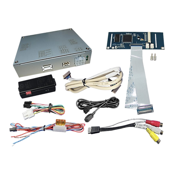
r.LiNK Video-inserter
RL2-MIB2-E
Compatible with
VW / SEAT / SKODA vehicles
with MIB2 Entry infotainment and 5inch monitor
Video-inserter with 2 video inputs and 1 rear-view camera input
Product features
Video-inserter for factory-infotainment systems
1 CVBS rear-view camera video-input
2 CVBS video-inputs for after-market devices (e.g. USB-Player, DVB-T2 tuner, ...)
Automatic switching to rear-view camera input on engagement of the reverse gear
Video-in-motion (ONLY for connected video-sources)
Video-inputs NTSC compatible
Version 22.01.2020
HW: 25(V31)
RL2-MIB2-E
Advertisement
Table of Contents

Related Manuals for NavLinkz r.LiNK RL2-MIB2-E


Summary of Contents for NavLinkz r.LiNK RL2-MIB2-E
- Page 1 r.LiNK Video-inserter RL2-MIB2-E Compatible with VW / SEAT / SKODA vehicles with MIB2 Entry infotainment and 5inch monitor Video-inserter with 2 video inputs and 1 rear-view camera input Product features Video-inserter for factory-infotainment systems 1 CVBS rear-view camera video-input ...
-
Page 2: Table Of Contents
Contents 1. Prior to installation 1.1. Delivery contents 1.2. Checking the compatibility of vehicle and accessories 1.3. Boxes and connectors 1.3.1. Video-Interface 1.3.2. CAN-bus box 1.3.3. Dip-switch settings 1.3.3.1. Enabling the interface’s video inputs (dip 2-3) 1.3.3.2. Rear-view camera setting (dip 5) 2. -
Page 3: Prior To Installation
Legal Information By law, watching moving pictures while driving is prohibited, the driver must not be distracted. We do not accept any liability for material damage or personal injury resulting, directly or indirectly, from installation or operation of this product. Apart from using this product in an unmoved vehicle, it should only be used to display fixed menus or rear-view- camera video when the vehicle is moving (for example the MP3 menu for DVD upgrades). -
Page 4: Checking The Compatibility Of Vehicle And Accessories
1.2. Checking the compatibility of vehicle and accessories Requirements Brand Compatible vehicles Infotainment Ibiza (6P) model years since 2016 MIB2 Entry - Media System Touch Color – Seat Leon3 (5F) model years since 2013 with 5inch monitor Toledo4 (KG) model years since 2016 Fabia3 (NJ) model years 2014-2017 Octavia3 (5E) model years 2012-2017 MIB2 Entry - Radio Swing - 5 inch color... -
Page 5: Boxes And Connectors
1.3. Boxes and connectors 1.3.1. Video Interface The video-interface converts the video signals of connected after-market sources in a factory monitor compatible picture signal which is inserted in the factory monitor, by using separate trigger options. Further it reads the vehicle’s digital signals out of the vehicle’s CAN-bus and converts them for the video interface. -
Page 6: Dip-Switch Settings
1.3.3. Dip-switch settings Some settings have to be selected by the dip-switches on the video interface. Dip position down is ON and position up is OFF. Function ON (down) OFF (up) No function set to OFF CVBS AV1-input enabled disabled CVBS AV2-input enabled disabled... -
Page 7: Installation
2. Installation To install the interface, first switch off the ignition and disconnect the vehicle’s battery. Please read the owner`s manual of the car, regarding the battery`s disconnection! If required, enable the car`s Sleep-mode (hibernation mode) In case the sleep-mode does not succeed, the disconnection of the battery can be done with a resistor lead. -
Page 8: Connection Schema
2.2. Connection schema Version 22.01.2020 HW: 25(V31) RL2-MIB2-E... -
Page 9: Connecting Video-Interface - Power/Can
2.3. Connecting video-interface – Power / CAN Connect the white female 6pin connector of the 6pin to 8pin cable to the male 6pin connector of the video interface. 1) Connect the red coloured wire of the 4pin Power / CAN cable to +12V ACC. 2) Connect the brown coloured wire of the 4pin Power /CAN cable to vehicle’s ground. -
Page 10: Connection Video-Interface - Analogue
2.4. Connecting video-interface – analogue If the communication between the CAN box and the vehicle’s CAN bus does not succeed (not all vehicles are compatible), an analogue connection is required by using the 6pin to 8pin cable with cut wire ends. Connect the female 6pin connector of the 6pin cable to the 6pin connector of the video interface. -
Page 11: Opening The Factory Monitor (Not Skoda Vehicles)
2.5. Opening the factory monitor (not Skoda vehicles) Remove the vehicle’s head-unit. Turn out both screws at the outer side of the top part of the head unit (red arrows) and both screws at the bottom part of the head unit (red arrows). Remove the head unit from the monitor and lay it aside. -
Page 12: Connection Of The 50Pin Ribbon Cables
2.6. Connection of the 50pin ribbon cables Fold upwards the black hinge of the factory ribbon cable base to unlock the original brown colored 50pin ribbon cable of the factory PCB. Carefully pull out the original 50pin ribbon cable in arrow direction. Note: The original short ribbon cable is made by stiff material. - Page 13 Carefully lead the monitor’s brown colored 50pin ribbon cable into the preassembled ribbon cable merger of the daughter PCB’s 50pin ribbon cable “PNL-OUT”. Make sure that the connector pins are faced to the merger’s platinum. After a check of its perfect position, close the ribbon cable merger’s lock, by folding back the black hinge, to fix the connection again.
-
Page 14: Warning Notes, Concerning The Installation Of Ribbon Cables
2.6.1. Warning notes, concerning the installation of ribbon cables 1) The contacting ends of ribbon cables always have to be installed in a straight and precise 180° position to the connector. Each deviation from a perfect contact position will curse faulty contact and even danger of short circuit 2) The ribbon cable’s contacting side always has to correspond to the contacting side of the connector, concerning the mounting position. -
Page 15: Assembly - Head Unit, Monitor And Daughter Pcb
2.8. Assembly - head unit, monitor and daughter PCB Carefully, plug the head unit into the monitor again and fix it with the 4 screws on its top and its bottom. Note: Take special care for the ribbon cables for they won’t be injured during the assembly of both parts! Change the original brass screws against the enclosed brass spacers at the position that’s shown in the picture. -
Page 16: Connection - Picture Signal Cable
2.9. Connection of the picture signal cable If not preassembled, connect the beige colored male 20pin connector (Monitor Side) of the 20pin picture signal cable to the female 20pin connector of the daughter PCB. Connect the opposite beige colored male 20pin connector (Box Side) of the picture signal cable to the female 20pin connector of the video interface. -
Page 17: Skoda Monitor - Removal And Opening
2.10.1. Skoda monitor – removal and opening. Turn out both screws at the outer side of the top part of the head unit (red arrows) and both screws at the bottom part of the head unit (red arrows). Separate the head unit from the monitor and lay it aside. -
Page 18: Skoda Monitor Mainboard - Disconnection And Removal
2.10.2. Skoda monitor mainboard – disconnection and removal Fold upwards the black hinge of the factory ribbon cable base to unlock the original brown colored 50pin ribbon cable of the factory PCB. Carefully pull out the original 50pin ribbon cable in arrow direction. Note: The original short ribbon cable is made by very stiff material. -
Page 19: Connection Of The 50Pin Ribbon Cables - Skoda
Clipp out the monitor’s mainboard from the monitor’s front housing and put it aside for setting free the monitor panel’s metal frame and the 50pin ribbon cable for its connection to the daughter PCB. Turn out the 4 screws and remove the monitor panel’s metal frame. 2.10.3. - Page 20 Carefully lead the monitor’s brown colored 50pin ribbon cable into the preassembled ribbon cable merger of the daughter PCB’s 50pin ribbon cable “PNL-OUT”. Make sure that the connector pins are faced to the merger’s platinum. After a check of its perfect position, close the ribbon cable merger’s lock, by folding back the black hinge, to fix the connection again.
- Page 21 Hold the factory mainboard in its right position, lead the daughter PCB’s 50pin ribbon cable „CAR-IN“ through its recess and again, fix the mainboard with two screws. Connect the daughter PCB’s 50pin ribbon cable to the factory mainboard’s free ribbon cable base. Make sure that the connector pins are faced to the platinum. After a check of its perfect position, close the ribbon cable base’s lock by folding downwards the black hinge, to fix the connection again.
-
Page 22: Reassembling - Skoda Head Unit And Monitor
2.10.4. Reassembling – Skoda monitor and head unit Lead the picture signal cable out at an appropriate location and reassemble the monitor’s rear housing part by using the 8 screws. Note: For the cable entry, a housing modification could possibly be required. Version 22.01.2020 HW: 25(V31) RL2-MIB2-E... - Page 23 Reassemble the head unit housing to the monitor housing. Take special care for the perfect fitting of both parts and for not to get caught the small white cables of the 12pin connector. Screw in both screws at the upside and both screws at the bottom of the head unit. Version 22.01.2020 HW: 25(V31) RL2-MIB2-E...
-
Page 24: Connection - Video Sources
2.11. Connection - Video-sources It is possible to connect two after-market video sources and one after-market rear-view camera to the video-interface. Before final installation of the peripheral devices, we recommend a test-run to detect a incompatibility of vehicle and interface. Due to changes in the production of the vehicle manufacturer there’s always a possibility of incompatibility. -
Page 25: Audio Insertion
2.12. Audio-insertion This interface is only able to insert video signals into the factory infotainment. If an AV- source is connected, the audio insertion has to be done by the factory audio AUX input or an FM-modulator. The inserted video-signal can be activated simultaneously to each audio- mode of the factory infotainment. -
Page 26: Case 2: Can-Box Does Not Receive The Reverse Gear Signal
2.13.2. . Case 2: CAN-box does not receive the reverse gear signal If the CAN-bus interface does not receive +12V on the green wire of the 6pin to 8pin cable when reverse gear is engaged (not all vehicles are compatible) an external switching signal from the reverse gear light is required. -
Page 27: Picture Settings
2.14. Picture settings The picture settings are adjustable by the 3 push-buttons on the video-interface. Press the MENU button to open the OSD settings menu or to switch to the next menu item. Press UP and DOWN to change the selected value. The buttons are placed inside in the housing to avoid accidental changes during or after the installation. -
Page 28: Video Interface Operation
3. Video interface operation The interface’s external keypad can be used to switch the enabled inputs. Each press will switch to the next enabled input. If all inputs are enabled the order is: Factory video video IN1 video IN2 factory video …... -
Page 29: Faq - Trouble Shooting-Interface Functions
FAQ – Trouble shooting Interface functions For any troubles which may occur, check the following table for a solution before requesting support from your vendor. Symptom Reason Possible solution Not all connectors have been reconnected to factory head- Connect missing connectors. unit or monitor after installation. -
Page 30: Technical Support
6pin to 8pin cable and isolate both ends. Technical Support Please note that direct technical support is only available for products purchased directly from NavLinkz GmbH. For products bought from other sources, contact your vendor for technical support. NavLinkz GmbH...
Need help?
Do you have a question about the r.LiNK RL2-MIB2-E and is the answer not in the manual?
Questions and answers