Table of Contents
Advertisement
Quick Links
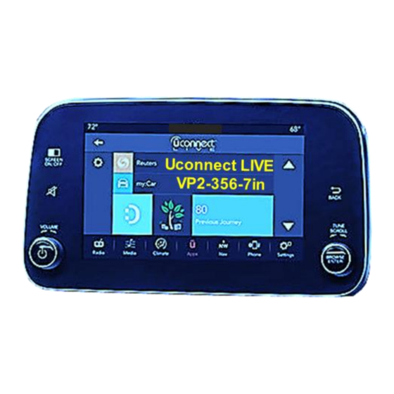
Compatible with Fiat vehicles with
and 7inch (VP2-356-7in) monitor
Video-inserter for front- and rear-view camera
Product features
Video-inserter for factory-infotainment systems
1 CVBS Input for rear-view camera
2 CVBS Video-inputs for after-market Video sources (e.g. DVD-Player, DVB-T Tuner)
Automatic switching to rear-view camera input on engagement of the reverse gear
Video-in-motion (ONLY for connected video-sources)
Video-inputs NTSC compatible
Version 10.02.2023
Video inserter
RL3-UCON7-T
Uconnect LIVE infotainment
and two more video inputs
HW:CAM(V98)/(V50+V41)
RL3-UCON7-T
Advertisement
Table of Contents

Related Manuals for NavLinkz RL3-UCON7-T


Summary of Contents for NavLinkz RL3-UCON7-T
- Page 1 Video inserter RL3-UCON7-T Compatible with Fiat vehicles with Uconnect LIVE infotainment and 7inch (VP2-356-7in) monitor Video-inserter for front- and rear-view camera and two more video inputs Product features Video-inserter for factory-infotainment systems 1 CVBS Input for rear-view camera ...
-
Page 2: Table Of Contents
Case 2: Interface does not receive the reverse gear signal 2.8. Connection - video-interface and external keypad 2.9. Picture settings 3. Interface operation 3.1. By factory infotainment button 3.2. By keypad 4. Specifications 5. FAQ – Trouble Shooting-Interface functions 6. Technical support Version 10.02.2023 HW:CAM(V98)/(V50+V41) RL3-UCON7-T... -
Page 3: Prior To Installation
Due to changes in the production of the vehicle manufacturer there’s always a possibility of incompatibility. 1.1. Delivery contents Take down the serial number of the interface and store this manual for support purposes: ____________________ Version 10.02.2023 HW:CAM(V98)/(V50+V41) RL3-UCON7-T... -
Page 4: Checking The Compatibility Of Vehicle And Accessories
The video-interface converts the connected after-market sources video signals into a LVDS signal which is inserted in the factory monitor using separate trigger options. Further it reads the vehicle’s digital signals out of the vehicle’s CAN-bus and converts them for the video interface. Version 10.02.2023 HW:CAM(V98)/(V50+V41) RL3-UCON7-T... -
Page 5: Settings Of The 8 Dip Switches (Black)
OFF. Dip position down is ON and position up is OFF. Vehicle/Navigation Dip 1 Dip 2 Dip 3 Dip 4 All vehicles After each Dip-switch-change a power-reset of the Can-box has to be performed! Version 10.02.2023 HW:CAM(V98)/(V50+V41) RL3-UCON7-T... -
Page 6: Installation
The interface needs a permanent 12V source! 2.1. Place of installation The interface is supposed to be installed at a suitable location behind the factory head-unit. The factory head unit is located behind the glove compartment. Version 10.02.2023 HW:CAM(V98)/(V50+V41) RL3-UCON7-T... -
Page 7: Connection Schema
2.2. Connection schema Version 10.02.2023 HW:CAM(V98)/(V50+V41) RL3-UCON7-T... -
Page 8: Connection - Picture Signal Cable
Connect the female waterblue coloured HSD+2 connector opposite the picture signal cable to the bordeaux coloured male HSD+2 connector of the video interface. Note: The colours of the HSD connector of head unit and factory harness may vary. Version 10.02.2023 HW:CAM(V98)/(V50+V41) RL3-UCON7-T... -
Page 9: Connection - 10Pin Power / Can Cable
Note: The CAN communication doesn’t succeed in all vehicles. If, after connecting the 10pin Power / CAN cable, no interface LED lightens up while the ignition is turned on, refer to chapter “Analogue power supply for the video interface”. Version 10.02.2023 HW:CAM(V98)/(V50+V41) RL3-UCON7-T... -
Page 10: Analog Power Supply For The Video Interface
2.5. Analog power supply for the video interface Connect the purple coloured wire Manual ACC of the 12pin interface cable to +12V ACC power supply Version 10.02.2023 HW:CAM(V98)/(V50+V41) RL3-UCON7-T... -
Page 11: Power Supply Output
2.6. Power supply output The red power supply output ACC-out Max 3A can be used to power an external source (max 3A). Version 10.02.2023 HW:CAM(V98)/(V50+V41) RL3-UCON7-T... -
Page 12: Connection - Video-Sources
Connect the video RCA of the Rear-view camera to the 12pin interface cable’s female RCA connector „Camera IN”. Connect the video RCA of the AV source 1 and 2 to the 12pin interface cable’s female RCA connector “Video IN 1” ” Video IN 2)”. Version 10.02.2023 HW:CAM(V98)/(V50+V41) RL3-UCON7-T... -
Page 13: Audio Insertion
“Camera IN” while the reverse gear is engaged. Additionally, the +12V (max. 3A) power supply for the rear-view camera can be taken from the green wire of the 12pin interface cable. Version 10.02.2023 HW:CAM(V98)/(V50+V41) RL3-UCON7-T... -
Page 14: Case 2: Interface Does Not Receive The Reverse Gear Signal
(86) of the relay. Connect the output connector (87) of the relay to the rear-view camera’s power- cable, like you did it to the green “Reverse-IN” cable before. Connect stabile and permanent +12V to the relay’s input connector (30). Version 10.02.2023 HW:CAM(V98)/(V50+V41) RL3-UCON7-T... -
Page 15: Connection - Video-Interface And External Keypad
Connect the female 4pin connector of the keypad to the male 4pin connector of the 12pin interface cable. Note: Even if switching through several video sources by the keypad mightn’t be required, the invisible connection and availability is strongly recommended. Version 10.02.2023 HW:CAM(V98)/(V50+V41) RL3-UCON7-T... -
Page 16: Picture Settings
The following settings are available: Contrast Brightness Saturation Position H (horizontal picture position) Position V (vertical picture position) IR-AV1/2 Guide L/R no function UI-CNTRL no function Size H/V (picture size horizontal/vertical) Version 10.02.2023 HW:CAM(V98)/(V50+V41) RL3-UCON7-T... -
Page 17: Interface Operation
Each press will switch to the next enabled input. Inputs which are not enabled will be skipped. Switchover by vehicle buttons isn’t possible in all vehicles. In some vehicles the external keypad has to be used. Version 10.02.2023 HW:CAM(V98)/(V50+V41) RL3-UCON7-T... -
Page 18: By Keypad
7V - 25V Stand-by power drain Power 280mA @12V Video input 0.7V - 1V Video input formats NTSC Temperature range -40°C to +85°C Dimensions video-box 119 x 24 x 95 mm (W x H x D) Version 10.02.2023 HW:CAM(V98)/(V50+V41) RL3-UCON7-T... -
Page 19: Faq - Trouble Shooting-Interface Functions
Camera input picture fluorescent light which shines Test camera under natural light outside the garage. flickers. directly into the camera. Camera input picture is Protection sticker not Remove protection sticker from lens. bluish. removed from camera lens. Version 10.02.2023 HW:CAM(V98)/(V50+V41) RL3-UCON7-T... -
Page 20: Technical Support
6pin to 8pin cable and isolate both ends. Technical Support Please note that direct technical support is only available for products purchased directly from NavLinkz GmbH. For products bought from other sources, contact your vendor for technical support. NavLinkz GmbH...
Need help?
Do you have a question about the RL3-UCON7-T and is the answer not in the manual?
Questions and answers