Table of Contents
Advertisement
Quick Links
UM0488
User manual
STM3210E-EVAL
evaluation board
Introduction
The STM3210E-EVAL evaluation board is designed as a complete development platform for
STMicroelectronic's ARM Cortex-M3 core-based STM32F103ZGT6 microcontroller with full
2
2
speed USB2.0, CAN2.0A/B compliant interface, two I
S channels, two I
C channels, five
USART channels with smartcard support, three SPI channels, two DAC channels, FSMC
interface, SDIO, internal 96 KB SRAM and 1 MB Flash, JTAG and SWD debug support.
The STM3210E-EVAL products delivered with the MB672 board versions D-03 or older are
based on the STM32F103ZET6 instead of the STM32F103ZGT6 and include 64 KB internal
SRAM and 512 KB Flash. The board number and version are on a label on the bottom side
of the board.
The full range of hardware features on the board helps you to evaluate all peripherals (USB,
motor control, CAN, MicroSD Card, smartcard, USART, NOR Flash, NAND Flash, SRAM)
and develop your own applications. Extension headers make it easy to connect a
daughterboard or wrapping board for your specific application.
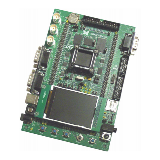
Figure 1.
STM3210E-EVAL evaluation board
July 2010
Doc ID 14220 Rev 5
1/48
www.st.com
Downloaded from
Elcodis.com
electronic components distributor
Advertisement
Table of Contents

Subscribe to Our Youtube Channel
Related Manuals for STMicroelectronics STM3210E-EVAL


Summary of Contents for STMicroelectronics STM3210E-EVAL
- Page 1 SDIO, internal 96 KB SRAM and 1 MB Flash, JTAG and SWD debug support. The STM3210E-EVAL products delivered with the MB672 board versions D-03 or older are based on the STM32F103ZET6 instead of the STM32F103ZGT6 and include 64 KB internal SRAM and 512 KB Flash.
-
Page 2: Table Of Contents
Contents UM0488 Contents Overview ..........4 Order code . - Page 3 Schematic diagrams ........29 Appendix A STM3210E-EVAL I/O assignment ......42 Revision history .
-
Page 4: Overview
STM3210E-EVAL demonstration software available from www.st.com To use the STM3210E-EVAL evaluation board, you must have the demonstration software version 1.1 or later. If the version installed on your evaluation board is earlier than version 1.1, you must download the latest version from www.st.com. -
Page 5: Hardware Layout And Configuration
UM0488 Hardware layout and configuration Hardware layout and configuration The STM3210E-EVAL evaluation board is designed around the STM32F103ZGT6 microcontroller in a 144-pin TQFP package. The hardware block diagram Figure 2 illustrates the connections between the STM32F103ZGT6 and peripherals (LCD, SPI Flash, USART,... - Page 6 Hardware layout and configuration UM0488 Figure 3. STM3210E-EVAL evaluation board layout CN10 CN11 STM32F103ZG Extension connector Extension connector Motor control CN2,3,5 connector CN14 Trace USART2 JTAG Color LCD CN13 MicroSD CN12 USART1 CN15 Audio jack IrDA CN17 5V power Potentiometer...
-
Page 7: Power Supply
Hardware layout and configuration Power supply The STM3210E-EVAL evaluation board is designed to be powered by 5V DC power supply and to be protected by PolyZen U15 in the event of wrong power plug-in. It is possible to configure the evaluation board to use any of following three sources for the power supply: 5V DC power adapter connected to CN17, the power jack on the board (PSU on silk screen for power supply unit). -
Page 8: Boot Option
X1, 8MHz crystal with socket for STM32F103ZGT6 microcontroller, it can be removed from socket when internal RC clock is used. Reset source The reset signal of the STM3210E-EVAL evaluation board is low active and the reset sources include: Reset button B1... -
Page 9: Audio
UM0488 Hardware layout and configuration Audio The STM3210E-EVAL evaluation board supports stereo audio play because it provides an audio DAC AK4343 connected to both I S port and two channels of DAC of microcontroller STM32F103ZGT6. Either external slave mode or PLL slave mode (reference clock BICK or LRCK) of audio DAC can be used by setting the jumper JP18. -
Page 10: Rs-232 Connectors
Motor control The STM3210E-EVAL evaluation board supports three-phase brushless motor control via a 34-pin connector CN1, which provides all required control and feedback signals to and from the motor power driving board. Available signals on this connector include emergency stop, motor speed, three-phase motor current, bus voltage, heatsink temperature from the motor driving board and 6 channels of PWM control signals going to the motor driving circuit. -
Page 11: Smartcard
Hardware layout and configuration 2.10 Smartcard STMicroelectronics smartcard interface chip ST8024 is used on the STM3210E-EVAL board for asynchronous 3 V and 5 V smartcards. It performs all supply protection and control functions based on the connections with STM32F103ZGT6 listed in Table The Smartcard_CMDVCC and Smartcard_OFF are multiplexed with motor control. -
Page 12: Temperature Sensor
I/O pin PC11 is data line 3 of the MicroSD Card when JP22 is open (default setting). 2.15 The STM3210E-EVAL evaluation board supports USB2.0 compliant full speed communication via a USB type B connector (CN14). The evaluation board can be powered by this USB connection at 5 V DC with a 500 mA current limitation. -
Page 13: Development And Debug Support
Hardware layout and configuration 2.16 Development and debug support The two debug connectors available on the STM3210E-EVAL evaluation board are: CN9: standard 20-pin JTAG interface connector, compliant with ARM7/9 debug tools. CN7: SAMTEC 20-pin connector FTSH-110-01-L-DV for both SWD and Trace, compliant with ARM CoreSight debug tools. -
Page 14: Sram
Hardware layout and configuration UM0488 Table 12. LCD modules (continued) TFT LCD CN16 (default) Graphic LCD U18 (optional) Pin on Pin on Description Pin connection Description Pin connection CN16 PD15 FSMC_D13 PD16 FSMC_D14 PD17 FSMC_D15 BL_GND BL_control 3.3V 3.3V 3.3V BL_VDD 3.3V PA6 via JP26... -
Page 15: Nor Flash
UM0488 Hardware layout and configuration 2.20 NOR Flash 128 Mbit NOR Flash is connected to bank1 NOR/PSRAM2 of the FSMC interface. The 16- bit operation mode is selected by a pull-up resistor connected to the BYTE pin of the NOR Flash. -
Page 16: Connectors
Connectors UM0488 Connectors Motor control connector CN1 Figure 4. Motor control connector CN1 (top view) 33 31 29 27 25 23 21 19 17 15 13 11 9 7 5 34 32 30 28 26 24 22 20 18 16 14 12 10 8 6 Table 16. -
Page 17: Analog Input Connectors Cn2, Cn3 And Cn5
1,4,8,9 CANH CANL 3,5,6 QST connector CN6 The QST connector connects the STM3210E-EVAL to the QST evaluation board to demonstrate the QST function. Figure 7. QST connector CN6 (front view) 13 11 9 7 5 3 1 14 12 10 8 6 4 2... -
Page 18: Trace Debugging Connector Cn7
Connectors UM0488 Table 19. QST connector CN6 Pin number Description Pin number Description PF11 Trace debugging connector CN7 Figure 8. Trace debugging connector CN7 (top view) 19 17 15 13 11 9 7 5 20 18 16 14 12 10 8 6 Table 20. -
Page 19: Rs-232 Connector Cn8 With Rts/Cts Handshake Support
UM0488 Connectors RS-232 connector CN8 with RTS/CTS handshake support Figure 9. RS-232 connector CN8 with RTS/CTS handshake support (front view) Table 21. RS-232 connector CN8 with RTS/CTS handshake support Pin number Description Pin number Description Connect to Pin 4 USART2_PA3 USART2_PA1 USART2_PA2 USART2_PA0... -
Page 20: Daughterboard Extension Connectors Cn10 And Cn11
Two 70-pin male headers CN10 and CN11 can be used to connect a daughterboard or standard wrapping board to the STM3210E-EVAL evaluation board. All total 112 GPI/Os are available on it. The space between these two connectors and the position of power, GND... - Page 21 Daughterboard extension connector CN10 (continued) How to disconnect from function block on Pin # Description Alternative function STM3210E-EVAL board Disconnect STM3210E-EVAL evaluation board from motor power drive board. Debug_TRST/MC Keep JP19 on open. Disconnect STM3210E-EVAL evaluation board from I2C_SCL/QST QST board.
- Page 22 FSMC_EBAR1 Remove R21. PG11 PG13 Joystick_Right Remove R103. PG15 Joystick_Up Remove R104. Debug_TDO Disconnect STM3210E-EVAL evaluation board from motor power drive board and QST board. MC/QST/Temperature sensor Remove R46. Disconnect STM3210E-EVAL evaluation board from I2C_SDA/QST QST board. CAN_TX Trace_D0/FSMC_A19 Trace_D2/FSMC_A21...
- Page 23 FSMC_D1 FSMC_D6 FSMC_D4 FSMC_A11 PF14 FSMC_A8 PF12 FSMC_A6 BOOT1/SPI_NSS Disconnect STM3210E-EVAL evaluation board from MC/QST motor power drive board and QST board. Disconnect STM3210E-EVAL evaluation board from Smartcard_3/5V/MC motor power drive board. Potentiometer Remove R126. Disconnect STM3210E-EVAL evaluation board from motor power drive board and QST board.
- Page 24 Daughterboard extension connector CN11 (continued) How to disconnect from function block on Pin # Description Alternative function STM3210E-EVAL board Disconnect STM3210E-EVAL evaluation board from MC/USART2_RTS motor power drive board. Disconnect STM3210E-EVAL evaluation board from motor power drive board. MC/BNC3 Disconnect analog signal from BNC3.
- Page 25 How to disconnect from function block on Pin # Description Alternative function STM3210E-EVAL board Disconnect STM3210E-EVAL evaluation board from motor power drive board. Disconnect STM3210E-EVAL evaluation board from MC/SPI_MOSI/QST motor power drive board and QST board. Disconnect STM3210E-EVAL evaluation board from QST board.
-
Page 26: Rs-232 Connector Cn12
Connectors UM0488 RS-232 connector CN12 Figure 11. RS-232 connector CN12 (front view) Table 25. RS-232 connector CN12 Pin number Description Pin number Description Connect to Pin 4 USART1_PA10 Connect to Pin 8 USART1_PA9 Connect to Pin 7 Connect to Pin 6 3.10 MicroSD Card connector CN13 Figure 12. -
Page 27: Usb Type B Connector Cn14
13 for details. 3.14 Power connector CN17 Your STM3210E-EVAL board can be powered from a DC 5 V power supply via the external power supply jack (CN17) shown in Figure 14. The central pin of CN17 must be positive. -
Page 28: Smartcard Connector Cn18
Connectors UM0488 3.15 Smartcard connector CN18 Figure 15. Smartcard connector CN18 (front view) 17 18 5 6 7 8 Table 28. Smartcard connector CN18 Pin number Description Pin number Description Detection pin of card presence Detection pin of card presence 28/48 Doc ID 14220 Rev 5 Downloaded from... -
Page 29: Schematic Diagrams
UM0488 Schematic diagrams Schematic diagrams This section provides the design schematics for the STM3210E-EVAL board key features, to help you implement these features in your applications. Schematics are provided for: Microcontroller connections, see Figure 16 MCU, see Figure 17 Peripherals, see... - Page 30 Schematic diagrams UM0488 Figure 16. Microcontroller connections 30/48 Doc ID 14220 Rev 5 Downloaded from Elcodis.com electronic components distributor...
- Page 31 UM0488 Schematic diagrams Figure 17. MCU Doc ID 14220 Rev 5 31/48 Downloaded from Elcodis.com electronic components distributor...
- Page 32 Schematic diagrams UM0488 Figure 18. Peripherals 32/48 Doc ID 14220 Rev 5 Downloaded from Elcodis.com electronic components distributor...
- Page 33 UM0488 Schematic diagrams Figure 19. RS-232 and IrDA connectors Doc ID 14220 Rev 5 33/48 Downloaded from Elcodis.com electronic components distributor...
- Page 34 Schematic diagrams UM0488 Figure 20. Audio 34/48 Doc ID 14220 Rev 5 Downloaded from Elcodis.com electronic components distributor...
- Page 35 UM0488 Schematic diagrams Figure 21. LCD and joystick connections Doc ID 14220 Rev 5 35/48 Downloaded from Elcodis.com electronic components distributor...
- Page 36 Schematic diagrams UM0488 Figure 22. SD Card and smartcard 36/48 Doc ID 14220 Rev 5 Downloaded from Elcodis.com electronic components distributor...
- Page 37 UM0488 Schematic diagrams Figure 23. Motor control Doc ID 14220 Rev 5 37/48 Downloaded from Elcodis.com electronic components distributor...
- Page 38 Schematic diagrams UM0488 Figure 24. JTAG and trace connectors 38/48 Doc ID 14220 Rev 5 Downloaded from Elcodis.com electronic components distributor...
- Page 39 UM0488 Schematic diagrams Figure 25. Power supply Doc ID 14220 Rev 5 39/48 Downloaded from Elcodis.com electronic components distributor...
- Page 40 Schematic diagrams UM0488 Figure 26. SRAM and Flash 40/48 Doc ID 14220 Rev 5 Downloaded from Elcodis.com electronic components distributor...
- Page 41 UM0488 Schematic diagrams Figure 27. Color LCD module Doc ID 14220 Rev 5 41/48 Downloaded from Elcodis.com electronic components distributor...
-
Page 42: Appendix A Stm3210E-Eval I/O Assignment
STM3210E-EVAL I/O assignment UM0488 Appendix A STM3210E-EVAL I/O assignment Table 29. STM3210E-EVAL I/O assignment Pin # Pin name STM3210E-EVAL I/O assignment Trace_CLK/FSMCA23 Trace_D0/FSMCA19 Trace_D1/FSMCA20 Trace_D2/FSMCA21 Trace_D3/FSMCA22 VBAT +3V3 or battery PC13-ANTI_TAMP Anti-tamper button PC14-OSC32_IN 32K OSC PC15-OSC32_OUT 32K OSC FSMCA0... - Page 43 UM0488 STM3210E-EVAL I/O assignment Table 29. STM3210E-EVAL I/O assignment (continued) Pin # Pin name STM3210E-EVAL I/O assignment VDDA +3V3 PA0-WKUP MC_TIM2_CH1 pin 31(Ena) / WAKEUP /USART2 CTS MC_TIM2_CH2 pin 33 (EnB)/USART2 RTS MC_TIM2_CH3 pin34 (EnIndex)/USART2 TX MC_TIM6_CH4 pin 23 (dissipative brake)/USART2 RX...
- Page 44 STM3210E-EVAL I/O assignment UM0488 Table 29. STM3210E-EVAL I/O assignment (continued) Pin # Pin name STM3210E-EVAL I/O assignment PE15 FSMCD12 PB10 Smart_IO PB11 Smart Reset VSS_1 VDD_1 +3V3 PB12 Smart_CK / MC_pin21 (NTC) / Audio I2S_CMD PB13 Audio I2S_CK PB14 USB Disconnect...
- Page 45 UM0488 STM3210E-EVAL I/O assignment Table 29. STM3210E-EVAL I/O assignment (continued) Pin # Pin name STM3210E-EVAL I/O assignment PA11 USB DM PA12 USB DP PA13 Debug TMS VSS_2 VDD_2 +3V3 PA14 Debug TCK PA15 Debug TDI PC10 IRDA TX / MicroSD Card D2...
- Page 46 STM3210E-EVAL I/O assignment UM0488 Table 29. STM3210E-EVAL I/O assignment (continued) Pin # Pin name STM3210E-EVAL I/O assignment BOOT0 BOOT0 CAN RX CAN TX FSMCBLN0 FSMCBLN1 VSS_3 VDD_3 +3V3 46/48 Doc ID 14220 Rev 5 Downloaded from Elcodis.com electronic components distributor...
-
Page 47: Revision History
UM0488 Revision history Revision history Table 30. Document revision history Date Revision Changes 5-May-2008 Initial release. Added information on NOR Flash references in Section 2.20. 2-Jun-2008 Updated schematics in Section Modified cover page. Inserted a newChapter 20-Nov-2008 Modified bank specified in Section 2.17, Section... - Page 48 Please Read Carefully: Information in this document is provided solely in connection with ST products. STMicroelectronics NV and its subsidiaries (“ST”) reserve the right to make changes, corrections, modifications or improvements, to this document, and the products and services described herein at any time, without notice.
Need help?
Do you have a question about the STM3210E-EVAL and is the answer not in the manual?
Questions and answers