Table of Contents
Advertisement
Quick Links
UM1011
User manual
STM32100E-EVAL demonstration firmware
Introduction
This user manual describes the demonstration firmware running on the STM32100E-EVAL
evaluation board, which can be used to evaluate the capabilities of the high-density value
line STM32F100ZET6 microcontroller and on-board peripherals.
This demo contains many applications that can be easily reused, such as RTC calendar, file
system FAT implementation on SD Card, Waveplayer with STM32 DAC peripheral, HDMI
CEC networking demo with an infrared remote control capability, temperature sensor
interfacing and TFT LCD with touch screen.
The STM32100E-EVAL board is delivered with the demonstration programmed in the
internal Flash memory, and all the files needed by the demonstration are programmed in the
MicroSD card. At each reset (board power-up, external reset, etc.), the demonstration is
executed.
In case the STM32100E-EVAL board was not factory-programmed or the demonstration
application was erased, the in-circuit programming (ICP) boot loader can be used to
program this file. For more details, refer to
Section 3: STM32100E-EVAL demonstration
package
and
Section 4: STM32100E-EVAL demonstration
programming.
This demonstration firmware is available for download from the STMicroelectronics website:
www.st.com.
April 2011
Doc ID 18064 Rev 1
1/49
www.st.com
Advertisement
Table of Contents

Subscribe to Our Youtube Channel
Related Manuals for STMicroelectronics STM32100E-EVAL


Summary of Contents for STMicroelectronics STM32100E-EVAL
- Page 1 User manual STM32100E-EVAL demonstration firmware Introduction This user manual describes the demonstration firmware running on the STM32100E-EVAL evaluation board, which can be used to evaluate the capabilities of the high-density value line STM32F100ZET6 microcontroller and on-board peripherals. This demo contains many applications that can be easily reused, such as RTC calendar, file...
-
Page 2: Table Of Contents
Contents UM1011 Contents Evaluation board overview ........7 Power control . - Page 3 About submenu ......... . . 43 STM32100E-EVAL demonstration package ..... . 44 Libraries .
- Page 4 List of tables UM1011 List of tables Table 1. STM32F100ZET6 demonstration peripherals........18 Table 2.
- Page 5 UM1011 List of figures List of figures Figure 1. Evaluation board overview ..........7 Figure 2.
- Page 6 About submenu............43 Figure 65. STM32100E-EVAL demonstration package directory tree ......44 Figure 66.
-
Page 7: Evaluation Board Overview
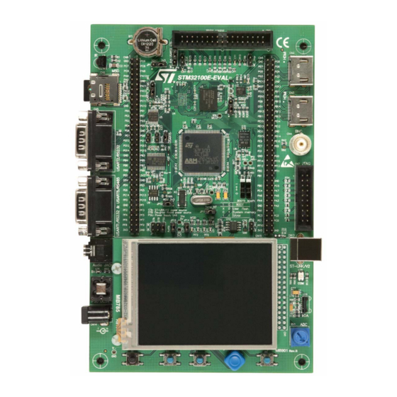
UM1011 Evaluation board overview Evaluation board overview The STM32100E-EVAL evaluation board provides a development and demonstration platform for STM32F100Zx-based applications. It is used to evaluate the major functions of the STM32F100ZET6 microcontroller. Figure 1 summarizes the main functional blocks of the evaluation board. -
Page 8: Power Control
The ST-LINK in-circuit debugger/programmer is embedded on the board. It supports the STM32F100ZET6 MCU. Display devices 1.7.1 A color LCD module is mounted on the STM32100E-EVAL board. It is interfaced through FSMC of STM32F100ZET6. 1.7.2 LEDs Four general-purpose LEDs are available. -
Page 9: Interfaces
DAC. 1.11.5 Storage memories The STM32100E-EVAL evaluation board features an 8 Mbyte SPI Flash memory and an SD Card™ memory connected to the SPI2 peripheral. It features also an 64 Kbyte I EEPROM memory connected to I2C2. -
Page 10: Temperature Sensor
Evaluation board overview UM1011 1.11.6 Temperature sensor The STM32100E-EVAL evaluation board includes an I C temperature sensor connected to the I2C2 peripheral. 10/49 Doc ID 18064 Rev 1... -
Page 11: Running The Demonstration
UM1011 Running the demonstration Running the demonstration Menu tree and navigation Figure 2 shows the menu system of the STM32F100ZET6 demonstration. The main menu is shown on the left-hand side. The UP, DOWN, RIGHT and LEFT joystick directions allow the user to navigate between items in the main menu and the submenus. -
Page 12: Demonstration Startup
Running the demonstration UM1011 Figure 2. Structure of the demonstration menus Demonstration startup The demonstration starts after a board reset. The system checks if an SD memory card is already plugged into the connector CN6. If no card detected, the demonstration does not start and the message shown in Figure 3 is displayed on the LCD screen. -
Page 13: Figure 3. Sd Card Check
UM1011 Running the demonstration Figure 3. SD Card check Please insert SD Card To continue the demonstration, insert an SD Card. The demonstration graphic icons and bitmap files are now checked in the MicroSD Card (see Section 2.6.5: External memory organization). -
Page 14: Time And Date Configuration
Running the demonstration UM1011 After some seconds, the following STM32 slide is displayed on the LCD screen: Figure 6. STM32 presentation slide Time and date configuration When the board is powered up for the first time and no power supply is detected on V (battery), you are prompted to set the time, year, month and day. -
Page 15: Navigation Procedure
UM1011 Running the demonstration Figure 8. Application main menu APP Main Menu Name Note: The icons shown in Figure 8 are taken from http://commons.wikimedia.org/wiki/Crystal_Clear. Once a submenu has been selected, the name of the application is listed at the top of the display and all the corresponding submenus are listed below as shown in Figure Figure 9. -
Page 16: Clock Sources
Running the demonstration UM1011 Figure 10. Navigating in the demonstration menus Clock sources 2.5.1 Clock control The STM32F100ZET6 internal clocks are derived from the HSE clocked by the external 8 MHz crystal. In this demonstration application, the various system clocks are configured as follows: ●... -
Page 17: Clock Failure
UM1011 Running the demonstration Figure 11. Clock tree diagram 2.5.2 Clock failure At any point of the demonstration, if no clock is present on OSC_IN (broken or disconnected crystal), the message shown in Figure 12 is displayed on the LCD screen. Figure 12. -
Page 18: Stm32F100Zet6 Resources
Running the demonstration UM1011 Figure 13. Standby mode entered STM32F100ZET6 resources 2.6.1 Peripherals All used peripherals are described in Table Table 1. STM32F100ZET6 demonstration peripherals Used peripherals Applications I2C2 Temperature sensor Calendar + demo kernel EXTI Menu navigation + joystick + push-button + low power modes GPIO All applications + LEDs NVIC... -
Page 19: Interrupts
UM1011 Running the demonstration 2.6.2 Interrupts Table 2 shows all the enabled interrupts. Table 2. STM32F100ZET6 demonstration interrupts Interrupts Priority Used for Preemption: 0 SysTick System timing SubPriority: 0 Preemption: 0 Calendar, date update SubPriority: 0 Preemption(fixed): -2 CSS interrupt Preemption: 2 EXTI0 Menu navigation... -
Page 20: External Interrupts
Figure 14. Internal Flash memory organization 2.6.5 External memory organization The STM32100E-EVAL demonstration is based on an embedded free FAT file system, DosFs . The file system is needed to read all media information from the on-board MicroSD memory card. -
Page 21: Figure 15. Microsd Card Organization
UM1011 Running the demonstration The SD Card memory is organized in two subdirectories: ● STFILES: this folder contains all required demo media files (icons, wave and slides). User files located in this folder cannot be handled by the demonstration; only default files are managed. -
Page 22: Demonstration Applications
Running the demonstration UM1011 Figure 16. Card removal Err: SDCard Removed Please check SD Card Press JoyStick UP to Restart the demo... Demonstration applications The following section provides a detailed description of each part of the demonstration. In the demonstration, the core runs at HCLK = 24 MHz. Four LEDs: LD1, LD2, LD3 and LD4 flash throughout the demonstration at a frequency depending on the core clock. -
Page 23: Figure 18. First Presentation Slide
Figure 18. First presentation slide Figure 19. Last presentation slide Product presentation speech The STM32100E-EVAL features an external audio amplifier used to play speech audio files through the embedded speaker. The properties of the product presentation speech wave file are the following: ●... -
Page 24: Calendar
To be able to use the battery to back up the RTC, the JP1 jumper must be in the position Battery-VDD on the STM32100E-EVAL board. In any submenu, if the time and date parameters have not yet been configured, the... -
Page 25: Figure 22. Setting The Time And Date
UM1011 Running the demonstration Figure 22. Setting the time and date You have the choice to set or not the time, year, month and day. Press any key (except for SEL) to ignore the prompt and abort the configuration sequence. Press on SEL and follow the setting sequence to set the time and date. -
Page 26: Figure 24. Time Show Submenu
Running the demonstration UM1011 Figure 24. Time Show submenu To exit the Time Show submenu, press the SEL push-button. To exit the Time submenu, select Return and press the SEL push-button. Date submenu This submenu is divided into two items that allow the user to display or set the current date. ●... -
Page 27: Figure 26. Setting The Month
UM1011 Running the demonstration Figure 26. Setting the month To select the day, use the UP, DOWN, RIGHT and LEFT push-buttons. After configuring the day, press the SEL push-button to store the entered value and exit to the Date submenu. The current date value is now displayed. -
Page 28: Figure 29. Setting The Alarm Activation Time
Running the demonstration UM1011 To exit this submenu, press the SEL push-button. To exit the Date submenu, select Return and press the SEL push-button. Alarm submenu You can use this submenu to configure the alarm activation time. When the alarm time value is reached, all the LEDs (LED1 to LED4) start flashing simultaneously for 30 seconds. -
Page 29: Image Viewer Submenu
UM1011 Running the demonstration Figure 31. Time and date not configured 2.7.3 Image Viewer submenu The Image Viewer submenu is used to demonstrate the LCD control performance using the embedded FSMC interface. The application displays successively the images stored on the MicroSD Card. -
Page 30: Wave Player Submenu
Running the demonstration UM1011 2.7.4 Wave Player submenu The STM32F100ZET6 microcontroller features an embedded DAC which can be used to generate output signals. In this demonstration, any wave file stored under the USER folder in the MicroSD Card can be opened using the file system DOSFS and transferred to the internal SRAM by block (512 bytes) using the DMA and the SPI interface. -
Page 31: Figure 35. Wave Player Playing Submenu
UM1011 Running the demonstration Figure 34, the active push-buttons and their functions are displayed. For example, at start-up, to play the file through the embedded speaker, press SEL. To exit the Wave Player submenu, press DOWN. The TAMPER push-button is used to select the speaker and the KEY push-button to select the headphone. -
Page 32: Low Power Modes
Running the demonstration UM1011 2.7.5 Low power modes The STM32F100ZET6 microcontroller features several operating modes in which the power consumption is reduced. The purpose of this menu is to demonstrate the behavior of the microcontroller in various low power modes. The Stop and Standby modes are used as examples. -
Page 33: Figure 39. Mcu In Stop Mode
UM1011 Running the demonstration Figure 39. MCU in Stop mode STOP Mode Wakeup by Tamper Press Joystick to continue ... Note: If an RTC Alarm is generated while the MCU is in Stop mode and the message shown in Figure 39 is displayed (which means that the TAMPER push-button needs to be pressed to exit Stop mode), the RTC Alarm wakes up the MCU from Stop mode. -
Page 34: Figure 42. Rtc Alarm Wakeup Configured
Running the demonstration UM1011 Once the alarm has been configured, the red LEDs stop blinking and the system enters Stop mode. The message shown in Figure 42 is displayed on the LCD. Figure 42. RTC Alarm wakeup configured MCU in Stop Mode Wait For RTC Alarm After the programmed time has elapsed, the system exits Stop mode. -
Page 35: Figure 45. Entering Standby Mode
UM1011 Running the demonstration Standby mode menu This menu allows the user to put the STM32F100ZET6 in Standby mode. The software runs the specific instruction sequence required by the STM32F100ZET6 to enter Standby mode. Figure 45. Entering Standby mode Standby Mode Exit: Wakeup Pin Exit: RTC Alarm Return... -
Page 36: Figure 47. Setting The Wakeup Time
Running the demonstration UM1011 Figure 47. Setting the wakeup time HH:MM:SS Once the alarm has been configured, the red LEDs stop blinking and the system enters Standby mode. The message shown in Figure 48 is then displayed on the LCD. Figure 48. -
Page 37: Infrared Decoding
The IR receiver TSOP34836 is connected to PC6 of STM32F100ZET6 on the STM32100E- EVAL board. Note: On STM32100E-EVAL RevA, the IR receiver TSOP34836 is connected to PA11. To select the Infrared Decoding menu, press SEL from the main menu or push on the IR icon. The IR submenu shown in Figure 50 is then displayed on the LCD screen. -
Page 38: Thermometer
C protocol including the System management bus (SMBus) mode. An STLM75 (or a compatible device) I C temperature sensor is mounted on the STM32100E-EVAL board and used to capture the external temperature (-55°C to +125°C). When the Thermometer submenu is selected, the message shown in Figure 52 displayed on the LCD. -
Page 39: Hdmi™ Cec Submenu
UM1011 Running the demonstration Figure 54. Warning temperature display Temperature Exceeding the T¬×Limi 32 C +xxx.x C +xxx.x F The message shown in Figure 54 is displayed on the LCD when the temperature goes under the over-limit low value (TEMPERATURE_THYS: Hysteresis Temperature). You can configure the TOS and THYS using dedicated #define statements in the code. -
Page 40: Figure 56. Hdmi Cec Submenu Selected
Running the demonstration UM1011 Figure 56. HDMI CEC submenu selected HDMI CEC HDMI CEC Return Once you select the HDMI CEC submenu, if no CEC error is generated, the device is configured as Tuner and the physical and logical addresses are displayed on the LCD as shown in Figure 57. -
Page 41: Figure 59. Select Cec Command
UM1011 Running the demonstration The feature CEC device also allows the user to command and control multiple audiovisual devices with one infrared remote control. After selecting the address, the user presses on the remote control and a command is sent by the CEC device. The message is displayed in the receiver field. -
Page 42: Help Submenu
Running the demonstration UM1011 Normally, for the Standby command, the device is in Stop mode and can wake up only when it receives a new command. However, you can use the TAMPER push-button to exit the HDMI-CEC submenu in case the demonstration is blocked. Any time in the CEC application, if you press the TAMPER push-button, the HDMI CEC stops and you return to the HDMI CEC submenu shown in Figure... -
Page 43: About Submenu
About submenu is selected, the message shown in Figure 64 is displayed on the LCD screen. Figure 64. About submenu About About Return Press SEL to display a message showing the STM32100E-EVAL demonstration version on the LCD screen. Doc ID 18064 Rev 1 43/49... -
Page 44: Stm32100E-Eval Demonstration Package
STM32100E-EVAL demonstration package UM1011 STM32100E-EVAL demonstration package The STM32100E-EVAL demonstration is supplied in one single zip file. The extraction of the zip file generates one folder, STM32100E-EVAL_FW_VX.Y.Z, which contains the subfolders shown in Figure 65 and described below. Figure 65. STM32100E-EVAL demonstration package directory tree... -
Page 45: Libraries
● RIDE: contains preconfigured projects for the RIDE toolchain ● TrueSTUDIO: contains preconfigured projects for the TrueSTUDIO toolchain Utilities STM32100E-EVAL: contains the LCD, and other STM32100E-EVAL board-related drivers. Doc ID 18064 Rev 1 45/49... -
Page 46: Stm32100E-Eval Demonstration Programming
STM32100E-EVAL demonstration programming Programming the media files The STM32100E-EVAL board comes with a MicroSD Card memory preprogrammed with the audio and image resources used by the demonstration. However, you can load your own image (*.bmp) and audio (*.wav) files in the USER directory, providing that these file formats are supported by the demonstration. -
Page 47: Using Iap
To program the demonstration's binary image into the internal Flash memory, you have to use the stm32100e-eval_fw_Usv1.0.0_offset_0x3000.bin file located under Project\STM32100E-EVAL\Binary with IAP over USART. For more details, please refer to IAP application note AN2557 STM32F10x in-application programming using the USART. -
Page 48: Revision History
Revision history UM1011 Revision history Table 4. Document revision history Date Revision Changes 14-Apr-2011 Initial release. 48/49 Doc ID 18064 Rev 1... - Page 49 UM1011 Please Read Carefully: Information in this document is provided solely in connection with ST products. STMicroelectronics NV and its subsidiaries (“ST”) reserve the right to make changes, corrections, modifications or improvements, to this document, and the products and services described herein at any time, without notice.
Need help?
Do you have a question about the STM32100E-EVAL and is the answer not in the manual?
Questions and answers