Table of Contents
Advertisement
Quick Links
Introduction
This user manual describes the demonstration firmware running on the STM32100B-EVAL
evaluation board, which can be used to evaluate the capabilities of the value line
STM32F100VB microcontroller and on-board peripherals.
The STM32100B-EVAL board is delivered with the demonstration programmed in the
internal Flash memory, and all the files needed by the demonstration are programmed in the
MicroSD card. At each reset (board power-up, external reset, etc.) the demonstration is
executed.
In case the STM32100B-EVAL board was not factory-programmed or the demonstration
application was erased, the in-circuit programming (ICP) boot loader can be used to
program this file. For more details, refer to
package
Note:
Before executing the demonstration, make sure that all evaluation board jumpers are well
configured. For more details, refer to STM32100B-EVAL board jumper configuration section.
This demonstration firmware is available for download from the STMicroelectronics website:
www.st.com.
February 2010
STM32100B-EVAL demonstration firmware
and
Section 4: STM32100B-EVAL demonstration
Doc ID 16982 Rev 1
Section 3: STM32100B-EVAL demonstration
programming.
UM0891
User manual
www.st.com
1/48
Advertisement
Table of Contents

Subscribe to Our Youtube Channel
Related Manuals for STMicroelectronics STM32100B-EVAL


Summary of Contents for STMicroelectronics STM32100B-EVAL
- Page 1 User manual STM32100B-EVAL demonstration firmware Introduction This user manual describes the demonstration firmware running on the STM32100B-EVAL evaluation board, which can be used to evaluate the capabilities of the value line STM32F100VB microcontroller and on-board peripherals. The STM32100B-EVAL board is delivered with the demonstration programmed in the internal Flash memory, and all the files needed by the demonstration are programmed in the MicroSD card.
-
Page 2: Table Of Contents
1.11.7 STM32100B-EVAL board jumper configuration ....10 Running the demonstration ........11 Menu tree and navigation . - Page 3 About submenu ......... . . 43 STM32100B-EVAL demonstration package ..... 44 Librairies .
- Page 4 List of tables UM0891 List of tables Table 1. STM32F100VB demonstration peripherals........17 Table 2.
- Page 5 UM0891 List of figures List of figures Figure 1. Evaluation board overview ..........7 Figure 2.
- Page 6 About submenu............43 Figure 69. STM32100B-EVAL demonstration package directory tree ......44 Figure 70.
-
Page 7: Evaluation Board Overview
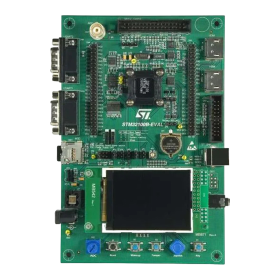
UM0891 Evaluation board overview Evaluation board overview The STM32100B-EVAL microcontroller evaluation board provides a development and demonstration platform for STM32F100xx-based applications. It allows to evaluate the major functions of the STM32F100VB microcontroller. Figure 1 summarizes the main functional blocks of the evaluation board. -
Page 8: Power Control
The ST-LINK in-circuit debugger/programmer is embedded on the board. It supports the STM32F100VB MCU. Display devices 1.7.1 A color LCD module is mounted on the STM32100B-EVAL board. It is interfaced through the embedded SPI peripheral. 1.7.2 Four general-purpose LEDs are available. -
Page 9: Interfaces
DAC. 1.11.5 Storage memories The STM32100B-EVAL evaluation board features an 8 Mbyte SPI Flash memory and an SD Card™ memory connected to the SPI1 peripheral. Doc ID 16982 Rev 1... -
Page 10: Temperature Sensor
The STM32100B-EVAL evaluation board includes an I C temperature sensor connected to the I2C1 peripheral. 1.11.7 STM32100B-EVAL board jumper configuration To run the STM32100B-EVAL demonstration correctly, you must configure the following STM32100B-EVAL board jumpers as follows: ● Audio DAC JP2: fitted ●... -
Page 11: Running The Demonstration
UM0891 Running the demonstration Running the demonstration Menu tree and navigation Figure 2 shows the menu system of the STM32F100VB demonstration. The main menu is shown on the left-hand side. The UP, DOWN, RIGHT and LEFT joystick directions allow the user to navigate between items in the main menu and the submenus. -
Page 12: Demonstration Startup
Running the demonstration UM0891 Demonstration startup The demonstration starts after a board reset. The system checks if an SD memory card is already plugged into the connector CN11. If no card detected, the demonstration does not start and the message shown in Figure 3 is displayed on the LCD screen. -
Page 13: Time And Date Configuration
UM0891 Running the demonstration After some seconds, the following STM32 slide is displayed on the LCD screen: Figure 6. STM32 family Time and date configuration When the board is powered up for the first time and no power supply is detected on V (battery), you are prompted to set the time, year, month and day. -
Page 14: Navigation Procedure
Running the demonstration UM0891 Figure 8. Application main menu APP Main Menu Name 1. The icons shown in Figure 8 are taken from http://commons.wikimedia.org/wiki/Crystal_Clear. Once a submenu has been selected, the name of the application is listed at the top of the display and all the corresponding submenus are listed below as shown in Figure Figure 9. -
Page 15: Clock Sources
UM0891 Running the demonstration Figure 10. Navigating in the demonstration menus Clock sources 2.5.1 Clock control The STM32F100VB’s internal clocks are derived from the HSE clocked by the external 8 MHz crystal. In this demonstration application, the different system clocks are configured as follows: ●... -
Page 16: Clock Failure
Running the demonstration UM0891 Figure 11. Clock tree diagram 2.5.2 Clock failure At any point of the demonstration, if no clock is present on OSC_IN (broken or disconnected crystal), the message shown in Figure 12 is displayed on the LCD screen. Figure 12. -
Page 17: Stm32F100Vb Resources
UM0891 Running the demonstration Figure 13. Standby mode entered STM32F100VB resources 2.6.1 Peripherals All used peripherals are described in Table Table 1. STM32F100VB demonstration peripherals Used peripherals Application I2C1 Temperature sensor Calendar + demo kernel EXTI Menu navigation + joystick + push button + low-power modes GPIO All applications + LEDs NVIC... -
Page 18: Interrupts
Running the demonstration UM0891 2.6.2 Interrupts Table 2 shows all the enabled interrupts. Table 2. STM32F100VB demonstration interrupts Interrupts Priority Used for Preemption: 0 SysTick System timing SubPriority: 0 Preemption: 0 Calendar, date update SubPriority: 0 Preemption(fixed): -2 CSS interrupt Preemption: 2... -
Page 19: External Interrupts
Figure 14. Internal Flash memory organization 2.6.5 External memory organisation The STM32100B-EVAL demonstration is based on an embedded free FAT file system, DosFs . The file system is needed to read all media information from the on-board MicroSD memory card. -
Page 20: Figure 15. Microsd Card Organization
Running the demonstration UM0891 Figure 15. MicroSD card organization At any point of the demonstration, if the SD card is removed, the demonstration stops and the message shown in Figure 16 is displayed on the LCD screen. Figure 16. SDCard removal Err: SDCard Removed Please check SD Card Press JoyStick UP to... -
Page 21: Demonstration Applications
UM0891 Running the demonstration Demonstration applications The following section provides a detailed description of each part of the demonstration. In the demonstration, the core runs at HCLK = 24 MHz. Four LEDs: LD1, LD2, LD3 and LD4 flash throughout the demonstration at a frequency depending on the core clock. 2.7.1 Product presentation This part of the demonstration presents all the STM32F100VB embedded peripherals and... -
Page 22: Figure 19. Last Presentation Slide
UM0891 Figure 19. Last presentation slide Product presentation speech The STM32100B-EVAL features an external audio amplifier used to play speech audio files through the embedded speaker or headphone. The properties of the product presentation speech wave file are the following: ●... -
Page 23: Calendar
To be able to use the battery to back up the RTC, the JP9 jumper must be in the position Battery-VDD on the STM32100B-EVAL board. In any submenu, if the time and date parameters have not yet been configured, the... -
Page 24: Figure 23. Time Adjust Submenu
Running the demonstration UM0891 Select Time Adjust. The message shown in Figure 23 is displayed on the LCD. To modify the first digit of the hour field, use the UP and DOWN push-buttons. Press UP to display the current value plus one. Press DOWN to display the previous digit value. After setting the digit value, press SEL. -
Page 25: Figure 25. Setting The Year
UM0891 Running the demonstration Date submenu This submenu is divided into two items that allow the user to display or set the current date. ● Date Adjust: this item has to be selected after each power-up in order to set the current date. -
Page 26: Figure 27. Setting The Day Of The Month
Running the demonstration UM0891 Figure 27. Setting the day of the month ● Date Show: this item displays the current date. If the time and date have not been previously configured, the message shown in Figure 28 is displayed. You have the choice to set the time/date or, to exit to the upper submenu. -
Page 27: Images Viewer Submenu
UM0891 Running the demonstration Figure 29. Setting the alarm activation time ● Alarm Show: this item displays the current alarm time. The default alarm activation time displayed after powering up is 00:00:00. The message shown in Figure 30 displayed on the LCD when this submenu is selected. Figure 30. -
Page 28: Wave Player Submenu
Running the demonstration UM0891 This application reads all bitmap pictures from the USER directory (see Section 4.1: Programming the media files) and displays only the .BMP files having the following format: ● Bit depth: 16-bit (RGB) ● Size: 240x320 The maximum images number that can be read from the MicroSD card is 25 images selected by alphabetic order. -
Page 29: Figure 34. Wave Player Submenu
UM0891 Running the demonstration the wave signal. The voice sampling period is read from the Wave File Header. An audio amplifier is connected to the DAC interface to play the stored wave files. This application illustrates all STM32 DAC features and modes by dedicated examples and lists the configuration steps for each mode. -
Page 30: Low-Power Modes
Running the demonstration UM0891 Figure 36. Wave Player Playing submenu STM32 DAC audio demo playing wave files PAUSE LEFT BWR DOWN STOP RIGHT FWD Playing USER/xxxxxxxx.WAV The progress bar and the volume bar are displayed at the bottom of the Wave Player Playing submenu. -
Page 31: Figure 38. Stop Mode Menu
UM0891 Running the demonstration Stop mode menu This menu allows you to put the STM32F100VB in Stop mode. The software performs the specific instruction sequence needed to enter Stop mode. Figure 38. Stop mode menu There are two ways to make the STM32F100VB exit Stop mode. ●... -
Page 32: Figure 41. Rtc Alarm Causes The Mcu To Exit The Stop Mode
Running the demonstration UM0891 Note: If an RTC Alarm is generated while the MCU is in Stop mode and the message shown in Figure 40 is displayed (which means that the Key push-button needs to be pressed to exit the Stop mode), the RTC Alarm causes the MCU to exit Stop mode. The message shown in Figure 41 is then displayed. -
Page 33: Figure 44. Rtc Alarm Wakeup
UM0891 Running the demonstration After the programmed time has elapsed, the system exits Stop mode. The system clock is then set to 24 MHz and the application resumes execution. The message shown in Figure 44 is displayed on the LCD screen. Figure 44. -
Page 34: Figure 47. Mcu In Standby Mode
Running the demonstration UM0891 There are two ways to make the STM32F100VB exit Standby mode. ● In the first case, you can use the Wakeup push-button. Once the Standby mode submenu has been selected, the red LEDs continue blinking until you press the “SEL” push-button, and the system enters Standby mode. -
Page 35: Figure 49. Setting The Wakeup Time
UM0891 Running the demonstration Figure 49. Setting the wakeup time HH:MM:SS Once the alarm has been configured, the red LEDs stop blinking and the system enters Standby mode. The message shown in Figure 50 is then displayed on the LCD. Figure 50. -
Page 36: Idd Measure Menu
The STM32F100VB microcontroller features an ADC peripheral. It measures the I current in Run, Sleep and Stop mode by using the I measurement circuit available on the STM32100B-EVAL board. To select the I Measure menu, press SEL from the main menu. The message shown in Figure 52 is then displayed on the LCD screen. -
Page 37: Thermometer
C protocol including the system management bus (SMBus) mode. An STLM75 (or a compatible device) I C temperature sensor is mounted on the STM32100B-EVAL board and used to get instantaneous external temperature (-55°C to +125°C) . When the Thermometer submenu is selected, the message shown in Figure 56 displayed on the LCD. -
Page 38: Figure 56. Thermometer Submenu Selected
Running the demonstration UM0891 Figure 56. Thermometer submenu selected Thermometer Temperature Return Once you select the Temperature submenu, the temperature value is displayed in Celsius and Fahrenheit as shown in Figure Press any key to return to the Thermometer submenu. Figure 57. -
Page 39: Hdmi Cec Submenu
UM0891 Running the demonstration The message shown in Figure 58 is displayed on the LCD when the temperature goes under the over-limit low value (TEMPERATURE_THYS: Hysteresis Temperature). You can configure the TOS and THYS thanks to dedicated #define statements in the code. By default they are set to (see menu.c file): #define TEMPERATURE_THYS 31 #define TEMPERATURE_TOS 32... -
Page 40: Figure 61. Hdmi Cec Configuration Submenu
Running the demonstration UM0891 Once you select the HDMI CEC submenu, if no CEC error is generated, the device is configured as Tuner and the physical and logical addresses are displayed on the LCD as shown in Figure 61. To enter the CEC menu, press the SEL push-button. Figure 61. -
Page 41: Help Submenu
UM0891 Running the demonstration When receiving a new message, the following information can be displayed on the LCD: ● Receive status ● Sender address ● Number of bytes (including the sender address) ● Opcode message ● Data (operands) Figure 64 shows that the device has correctly received the frame from the sender with address: 0x5, number of bytes received: 0x3 (header + opcode + data), message opcode: 0x44 and data: 0x41... -
Page 42: Figure 65. Help Submenu
Running the demonstration UM0891 Figure 65. Help submenu Help Start Return If you press SEL, the image shown in Figure 66 is displayed on the LCD screen. Figure 66. Joystick buttons Press any joystick push-button to display the next help slide as shown in Figure Figure 67. -
Page 43: About Submenu
About submenu is selected, the message shown in Figure 68 is displayed on the LCD screen. Figure 68. About submenu About About Return Pressing SEL displays a message showing the STM32100B-EVAL demonstration version on the LCD screen. Doc ID 16982 Rev 1 43/48... -
Page 44: Stm32100B-Eval Demonstration Package
STM32100B-EVAL demonstration package UM0891 STM32100B-EVAL demonstration package The STM32100B-EVAL demonstration is supplied in one single zip file. The extraction of the zip file generates one folder, STM32100B-EVAL_FW_VX.Y.Z, which contains the subfolders shown in Figure 69 and described below. Figure 69. STM32100B-EVAL demonstration package directory tree... -
Page 45: Project
HiTOP: contains preconfigured projects for the HiTOP toolchain ● inc subfolder: contains the demonstration header files ● src subfolder: contains the demonstration source files Utilities STM32100B-EVAL: contains the LCD, and other STM32100B-EVAL board-related drivers. Doc ID 16982 Rev 1 45/48... -
Page 46: Stm32100B-Eval Demonstration Programming
STM32100B-EVAL demonstration programming Programming the media files The STM32100B-EVAL board comes with an MircoSD card memory preprogrammed with audio and image resources used by the demonstration. However you can load your own image (*.bmp) and audio (*.wav) files in the “USER” directory, providing that these file formats are supported by the demonstration. -
Page 47: Revision History
UM0891 Revision history Revision history Table 4. Document revision history Date Revision Changes 26-Feb-2010 Initial release. Doc ID 16982 Rev 1 47/48... - Page 48 Please Read Carefully: Information in this document is provided solely in connection with ST products. STMicroelectronics NV and its subsidiaries (“ST”) reserve the right to make changes, corrections, modifications or improvements, to this document, and the products and services described herein at any time, without notice.
Need help?
Do you have a question about the STM32100B-EVAL and is the answer not in the manual?
Questions and answers