Table of Contents
Advertisement
Quick Links
We have 45,000 LP502030-PCM-NTC-LD-A02554 - EEMB - Lithium Battery Rectangular 3.7V 250mAh Rechargeable in
stock now. Starting at $0.034. This EEMB part is fully warrantied and traceable.
Looking for a discount?
Check out our current promotions!
This coversheet was created by Verical, a division of Arrow Electronics, Inc. ("Verical"). The attached document was created by the part supplier,
not Verical, and is provided strictly 'as is.' Verical, its subsidiaries, affiliates, employees, and agents make no representations or warranties
regarding the attached document and disclaim any liability for the consequences of relying on the information therein. All referenced brands,
product names, service names, and trademarks are the property of their respective owners.
00000005981LF-000
STM32439I-EVAL2
EOS Power
STMICROELECTRONICS
Buy Now
Buy Now
Give us a call
1-855-837-4225
International: 1-555-555-5555
1-415-281-3866
1-415-281-3866
Arrow Electronics,
Arrow Electronics, Inc
Verical Division
9201 East Dry Creek Road
P.O. Box 740970
Centennial, CO 80112
Los Angeles, CA 90074-0970
Advertisement
Table of Contents

Subscribe to Our Youtube Channel
Related Manuals for STMicroelectronics STM32439I-EVAL


Summary of Contents for STMicroelectronics STM32439I-EVAL
- Page 1 We have 45,000 LP502030-PCM-NTC-LD-A02554 - EEMB - Lithium Battery Rectangular 3.7V 250mAh Rechargeable in stock now. Starting at $0.034. This EEMB part is fully warrantied and traceable. 00000005981LF-000 STM32439I-EVAL2 EOS Power STMICROELECTRONICS Buy Now Buy Now Looking for a discount? Check out our current promotions!
- Page 2 UM1668 User manual STM32439I-EVAL evaluation board for the STM32F439 line Introduction The STM32439I-EVAL evaluation board is a complete demonstration and development ® ® platform for STMicroelectronics ARM Cortex -M4 core-based STM32F439NIH6 microcontrollers. It features three I C, six SPIs with two muxed full-duplex I...
-
Page 3: Table Of Contents
Contents UM1668 Contents Overview ..........6 Features . - Page 4 Schematics ..........43 Appendix A STM32439I-EVAL I/O assignment ......61 Appendix B Mechanical dimensions.
- Page 5 STM32439I-EVAL I/O assignment ........
- Page 6 STM32439I-EVAL evaluation board ........
-
Page 7: Overview
Demonstration software Demonstration software is preloaded in the Flash memory of the board for easy demonstration of the device peripherals in stand-alone mode. For more information and to download the latest version, refer to the STM32439I-EVAL demonstration software on www.st.com. 6/70... -
Page 8: Order Code
UM1668 Overview Order code To order the evaluation board based on STM32F439NIH6 MCU and 5.7" TFT LCD, use the order code STM32439I-EVAL2. Delivery recommendations Some verifications are needed before using the board for the first time to make sure that nothing was damaged during shipment and that no components are unplugged or lost. -
Page 9: Hardware Layout And Configuration
Hardware layout and configuration UM1668 Hardware layout and configuration The STM32439I-EVAL evaluation board is designed around the STM32F439NIH6 (216-pin TFBGA package). The hardware block diagram Figure 2 illustrates the connection between the STM32F439NIH6 and peripherals (SDRAM, SRAM, NOR Flash, camera module, color... -
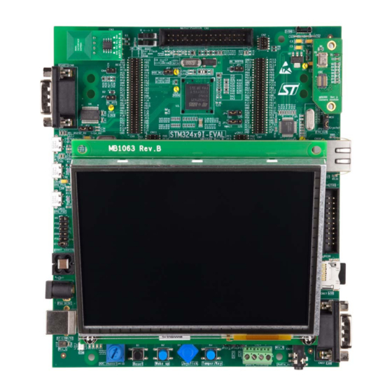
Page 10: Figure 3. Evaluation Board Layout
UM1668 Hardware layout and configuration Figure 3. Evaluation board layout DocID025151 Rev 2 9/70... -
Page 11: Development And Debug Support
Hardware layout and configuration UM1668 Development and debug support Version 2 of the ST-LINK (ST-LINK/V2) is embedded on the board. This tool allows on-board program loading and debugging of the STM32 using a JTAG or SWD interface. Third-party debug tools are also supported by the JTAG/SWD connector, CN16, and ETM Trace connector, CN13. -
Page 12: Power Supply
Hardware layout and configuration Power supply The STM32439I-EVAL evaluation board is designed to be powered by a 5 V DC power supply and is protected by PolyZen from a wrong power plug-in event. It is possible to configure the evaluation board to use any of following six sources for the power supply: •... - Page 13 CN6 & CN7, JP12 is set as shown to the right (daughterboard must not have its own power supply connected) The LED LD10 is lit when the STM32439I-EVAL evaluation board is powered by the 5 V correctly. Note:...
-
Page 14: Clock Source
Jumper JP6 for Ethernet clock refer to Section 2.13. Reset source The reset signal of STM32439I-EVAL evaluation board is low active. Reset sources include: • Reset button B1 • Debugging tools from JTAG/SWD connector CN16 and ETM trace connector CN13 •... -
Page 15: Boot Option
0 < > 1 Note: The RS-232 boot loader mechanism is not supported on the STM32439I-EVAL. Audio An audio codec WM8994ECS/R with 4 DACs and 2 ADCs inside is connected to the SAI interface of the STM32F439NIH6 to support the TDM feature on the SAI port. This feature implements audio recording on digital and analog microphone, and audio playback of different audio streams on headphone and line-out at the same time. -
Page 16: Usb Otg1 Fs
Power switch (U9) is ON and the STM32439I-EVAL is acting as a USB host. • VBUS is powered by another USB host and the STM32439I-EVAL is acting as a USB device. Red LED LD8 will be lit when over-current occurs. -
Page 17: Usb Otg2 Hs & Fs
• Power switch (U6) is ON and STM32439I-EVAL is acting as a USB host. • VBUS is powered by another USB host, and STM32439I-EVAL is acting as a USB device. Red LED LD6 is lit if over-current occurs. RS-232 & IrDA... -
Page 18: Microsd Card
RF-EEPROM An RF-EEPROM daughterboard ANT7-M24LR-A is mounted on CN3 of the STM32439I-EVAL board via the I2C1 bus. The RF-EEPROM can be accessed by the microcontroller via the I2C1 bus or by radio frequency (RF) using a 13.56 MHz reader (for example, CR95HF). -
Page 19: Ethernet
UM1668 2.13 Ethernet The STM32439I-EVAL evaluation board supports 10M/100M Ethernet communication by a PHY DP83848CVV (U5) and integrated RJ45 connector (CN10). Ethernet PHY is connected to the STM32F439NIH6 via the MII interface. A 25 MHz clock can be generated by PHY or provided by MCO from the STM32F439NIH6... -
Page 20: Memories
C24 with the resistor and capacitor requested by end user's application. 2.17 Camera module Connector CN5 (for DCMI signals) on the STM32439I-EVAL evaluation board connects to the camera module daughterboard MB1066. DCMI signals are duplicated with other peripherals (SAI, I2S, NOR Flash, MicroSD Card, Trace, Ethernet). -
Page 21: Display And Input Devices
Hardware layout and configuration UM1668 2.18 Display and input devices A 5.7 inch 640 x 480 TFT color LCD with capacitive touch panel can be connected to the RGB LCD interface of STM32F439NIH6. 4 general purpose color LED's (LD 1,2,3,4) are available as display devices. The 4-direction joystick (B4), Wakeup (B2) and Tamper/key button (B3) are available as input devices. -
Page 22: Motor Control
Figure 4. Orientation setting of 5.7 inch LCD daughterboard 2.19 Motor control The STM32439I-EVAL evaluation board supports both asynchronous and synchronous three-phase brushless motor control via a 34-pin connector, CN1, which provides all required control and feedback signals to and from motor power-driving board. -
Page 23: Figure 5. Pcb Underside Rework For Motor Control
Hardware layout and configuration UM1668 All resistors to be removed on the underside of the board are marked in red, while resistors to be soldered are marked in green in Figure Figure 6 shows all resistors to be removed on the topside of the board marked in red, while resistors to be soldered are marked in green (removal of R102 and R104, and mounting of R16). -
Page 24: Table 14. Motor Control Related Solder Bridges
UM1668 Hardware layout and configuration Table 14. Motor control related solder bridges Solder bridges Description The special motor current sampling operation is enabled when SB1 is closed (PA12 connected to PA8). The I/O pins PA12 and PA8 are disconnected and can be used by a daughterboard when SB1 is not fitted. -
Page 25: Connectors
Connectors UM1668 Connectors Motor control connector CN1 Figure 7. Motor control connector CN1 Table 15. Motor control connector CN1 STM32F439NIH6 CN1 pin STM32F439NIH6 Description Description number pin number Emergency stop PA6 MC_UH MC_UL MC_VH MC_VL MC_WH MC_WL Bus voltage current A current B current C NTC bypass... -
Page 26: Extension Connector Cn2
UM1668 Connectors Extension connector CN2 Figure 8. Extension connector CN2 top view Table 16. Extension connector CN2 Pin number Pin name I2C interface description SPI interface description I2C1_SDA SPI3_CS PC11 SPI3_MISO I2C1_SCL EXT_RESET PC10 EXT_RESET SPI3_SCK PC12 SPI3_MOSI DocID025151 Rev 2 25/70... -
Page 27: Rf-Eeprom Daughterboard Connector Cn3
Connectors UM1668 RF-EEPROM daughterboard connector CN3 Figure 9. RF-EEPROM daughterboard connector CN3 (front view) Table 17. RF-EEPROM daughterboard connector CN3 Pin number Description Pin number Description I2C1_SDA (PB9) +3V3 SPI3_MISO (PC11) Reserved for future use (PC12) I2C1_SCL (PB6) RESET(PC10) Analog input connector CN4 Figure 10. -
Page 28: Camera Module Connector Cn5
UM1668 Connectors Camera module connector CN5 Figure 11. Camera module connector CN5 (top view) Table 19. Camera module connector CN5 Pin number Description Pin number Description +1.8 V +1.8 V D0 (PC6) D1 (PC7) D2 (PC8) D10 (PD6) D3 (PC9) D11 (PD2) D4 (PC11) D5(PD3) -
Page 29: Daughterboard Extension Connector Cn6 And Cn7
Daughterboard extension connector CN6 and CN7 Two 60-pin male headers CN6 and CN7 can connect a daughterboard or standard wrapping board to the STM32439I-EVAL evaluation board. All GPI/Os are available on them and memory connectors (CN11 & CN12). The space between these two connectors is defined as a standard which allows common daughterboards to be developed for several evaluations boards. - Page 30 UM1668 Connectors Table 20. Daughterboard extension connector CN6 (continued) How to disconnect with function block on Pin Description Alternative function STM32439I-EVAL board ULPI_D5/ PB12 Remove R108, R260, Disconnect CN15 USB_FS2_ID ULPI_D6/ PB13 Remove R112, R264, Disconnect CN15 USB_FS2_VBUS LCD_G2 LED2...
-
Page 31: Table 21. Daughterboard Extension Connector Cn7
Connectors UM1668 Table 20. Daughterboard extension connector CN6 (continued) How to disconnect with function block on Pin Description Alternative function STM32439I-EVAL board LCD_R6 LCD_R7 MII_RXD1/ Remove R263, R267 MC_HEATSINK +3V3 ULPI_D1/MC_VL Remove R102, R282 LCD_R1 LCD_R3 LCD_R2 Table 21. Daughterboard extension connector CN7... - Page 32 UM1668 Connectors Table 21. Daughterboard extension connector CN7 (continued) How to disconnect with function block on Pin Description Alternative function STM32439I-EVAL board LCD_G5 CAN1_RX/ USB_FS1_DM/ PA11 Remove R255, R298, Keep JP16 on open MC_PFCpwm RS232_IRDA_TX/ Remove R262, R266 USB_FS1_VBUS JTDO- SWO/...
- Page 33 Connectors UM1668 Table 21. Daughterboard extension connector CN7 (continued) How to disconnect with function block on Pin Description Alternative function STM32439I-EVAL board SDCARD_CK/ PC12 SPI3_MOSI/ Disconnect CN2, CN3, CN5, CN17 PAR_D9 PA15 JTDI Remove R106 LCD_G6 PA14 JTCK-SWCLK Remove R99...
-
Page 34: Rs-232 Connector Cn8
UM1668 Connectors RS-232 connector CN8 Figure 12. RS-232 connector (front view) Table 22. RS-232 connector CN8 with ISP support Pin number Description Pin number Description RS232_RX (PA10) RS232_TX (PA9) USB OTG2 HS Micro-AB connector CN9 Figure 13. USB OTG2 HS Micro-AB connector CN9 (front view) Table 23. -
Page 35: Ethernet Rj45 Connector Cn10
The standard width between the CN11 pin1 and CN12 pin1 is 1914 mils (48.62 mm). For signal assignments refer to Table 25 Table 26 for detail. Table 25. Memory connector CN11 How to disconnect with function block on Pin Description Alternative function STM32439I-EVAL board SDNE0/ Remove SB8 MII_COL PF13 PF12 PE10 PE12... - Page 36 UM1668 Connectors Table 25. Memory connector CN11 (continued) How to disconnect with function block on Pin Description Alternative function STM32439I-EVAL board PE13 PD11 PD12 A15/ PH11 PD13 PD14 SDNWE PF14 PF11 SDNRAS PE11 PF15 PE14 PH10 A14/ PH12 PD10 PD15...
-
Page 37: Table 26. Memory Connector Cn12
Connectors UM1668 Table 26. Memory connector CN12 How to disconnect with function block on Pin Description Alternative function STM32439I-EVAL board A22/ SAI1_SD_A/ Remove R114, R120, R128 TRACED3/ PAR_D7 A20/ Remove R33 TRACED1 A19/ Remove R39 TRACED0 NBL3 NBL2 PG15 SDNCAS... -
Page 38: Etm Trace Debugging Connector Cn13
UM1668 Connectors Table 26. Memory connector CN12 (continued) How to disconnect with function block on Pin Description Alternative function STM32439I-EVAL board PH15 PH14 +3.3V 3.11 ETM trace debugging connector CN13 Figure 15. ETM trace debugging connector CN13 (top view) Table 27. ETM trace debugging connector CN13... -
Page 39: Usb Otg1 Fs Micro-Ab Connector Cn14
Connectors UM1668 Table 27. ETM trace debugging connector CN13 Pin number Description Pin number Description TraceD2/PE5 TraceD3/PE6 3.12 USB OTG1 FS Micro-AB connector CN14 Figure 16. USB OTG1 FS Micro-AB connector CN14 (front view) Table 28. USB OTG1 FS Micro-AB connector CN14 Pin number Description Pin number... -
Page 40: Jtag/Swd Connector Cn16
UM1668 Connectors 3.14 JTAG/SWD connector CN16 Figure 18. JTAG/SWD debugging connector CN16 (top view) Table 30. JTAG/SWD debugging connector CN15 Pin number Description Pin number Description +3.3V +3.3V PA15 PA13 PA14 RTCK RESET# DBGRQ DBGACK 3.15 MicroSD connector CN17 Figure 19. MicroSD connector CN17 (front view) DocID025151 Rev 2 39/70... -
Page 41: Power Connector Cn18
GPIOx are I/O expander (U16) signals. 3.16 Power connector CN18 The STM32439I-EVAL evaluation board can be powered from a DC 5 V power supply via the external power supply jack (CN18) shown in Figure 20. The central pin of CN18 must be positive. -
Page 42: St-Link/V2 Usb Type B Connector Cn21
Pin number Description Pin number Description 1,4,8,9 CANH CANL 3,5,6 3.21 Audio jack CN23 A 3.5 mm stereo audio jack CN23 is available on the STM32439I-EVAL evaluation board to support a headset (headphone & microphone integrated). DocID025151 Rev 2 41/70... -
Page 43: Audio Terminal Cn24
Connectors UM1668 3.22 Audio terminal CN24 Figure 23. Audio terminal CN24 (front view) Table 34. Audio terminal CN24 Pin number Description Pin number Description SPKOUT_L_N SPKOUT_R_N SPKOUT_L_P SPKOUT_R_P 3.23 ST-LINK/V2 programming Tag-connector CN25 The connector CN25 is used only by the embedded ST-LINK/V2 programming during board manufacture with Tag-connector (TC2050-IDC). -
Page 44: Schematics
UM1668 Schematics Schematics Figure 24. STM32439I-EVAL DocID025151 Rev 2 43/70... -
Page 45: Figure 25. Mcu
Schematics UM1668 Figure 25. MCU 44/70 DocID025151 Rev 2... -
Page 46: Figure 26. Power
UM1668 Schematics Figure 26. Power DocID025151 Rev 2 45/70... -
Page 47: Figure 27. Sram, Flash And Sdram
Schematics UM1668 Figure 27. SRAM, Flash and SDRAM 46/70 DocID025151 Rev 2... -
Page 48: Figure 28. Audio
UM1668 Schematics Figure 28. Audio DocID025151 Rev 2 47/70... -
Page 49: Figure 29. Lcd, Camera And Connectors
Schematics UM1668 Figure 29. LCD, camera and connectors 48/70 DocID025151 Rev 2... -
Page 50: Figure 30. Ethernet
UM1668 Schematics Figure 30. Ethernet DocID025151 Rev 2 49/70... -
Page 51: Figure 31. Usb Otg Hs
Schematics UM1668 Figure 31. USB OTG HS 50/70 DocID025151 Rev 2... -
Page 52: Figure 32. Usb Otg Fs
UM1668 Schematics Figure 32. USB OTG FS DocID025151 Rev 2 51/70... -
Page 53: Figure 33. Rs-232 And Irda
Schematics UM1668 Figure 33. RS-232 and IrDA 52/70 DocID025151 Rev 2... -
Page 54: Figure 34. Can, Microsd Card And Io Expander
UM1668 Schematics Figure 34. CAN, MicroSD Card and IO expander DocID025151 Rev 2 53/70... -
Page 55: Figure 35. Peripherals
Schematics UM1668 Figure 35. Peripherals 54/70 DocID025151 Rev 2... -
Page 56: Figure 36. Motor Control
UM1668 Schematics Figure 36. Motor control DocID025151 Rev 2 55/70... -
Page 57: Figure 37. Extension Connector
Schematics UM1668 Figure 37. Extension connector 56/70 DocID025151 Rev 2... -
Page 58: Figure 38. St-Link/V2
UM1668 Schematics Figure 38. ST-LINK/V2 DocID025151 Rev 2 57/70... -
Page 59: Figure 39. Jtag And Trace
Schematics UM1668 Figure 39. JTAG and trace 58/70 DocID025151 Rev 2... -
Page 60: Figure 40. 5.7' Tft Lcd Daughterboard Mb1063
UM1668 Schematics Figure 40. 5.7' TFT LCD daughterboard MB1063 DocID025151 Rev 2 59/70... -
Page 61: Figure 41. Camera Daughterboard Mb1066
Schematics UM1668 Figure 41. Camera daughterboard MB1066 60/70 DocID025151 Rev 2... -
Page 62: Appendix A Stm32439I-Eval I/O Assignment
UM1668 STM32439I-EVAL I/O assignment Appendix A STM32439I-EVAL I/O assignment Table 35. STM32439I-EVAL I/O assignment Motor control Camera Pin number Pin name STM32439I-EVAL standard variant variant A20/ TRACED1 A19/ TRACED0 TRACECLK PG14 MII_TXD1 NBL1 NBL0 MII_TXD3 DISSIPATIVE_BRAKE D6 ULPI_D7 JTRST JTDO-SWO/... - Page 63 STM32439I-EVAL I/O assignment UM1668 Table 35. STM32439I-EVAL I/O assignment (continued) Motor control Camera Pin number Pin name STM32439I-EVAL standard variant variant SDCARD_D3/ PC11 SPI3_MISO SDCARD_D2/ PC10 SPI3_SCK CAN1_TX/ PA12 PFC_SYNC2 USB_FS1_DP VBAT VBAT PI8- ANTI EXPANDER_INT TAMP2 NBL2 LCD_DE LCD_B7...
- Page 64 UM1668 STM32439I-EVAL I/O assignment Table 35. STM32439I-EVAL I/O assignment (continued) Motor control Camera Pin number Pin name STM32439I-EVAL standard variant variant SDCARD_CMD PH15 RS232_IRDA_RX/ PA10 USB_FS1_VBUS/ USB_FS1_ID PC14 OSC32_IN PI12 LCD_HSYNC PDR_ON BOOT0 BOOT0 VDD_3 VDD_11 VDD_10 VDD_15 VCAP2 PH13...
- Page 65 STM32439I-EVAL I/O assignment UM1668 Table 35. STM32439I-EVAL I/O assignment (continued) Motor control Camera Pin number Pin name STM32439I-EVAL standard variant variant LCD_G7 SDCARD_D1 LCD_BL_CTRL PFC_SYNC1 OSC_IN PI13 LCD_VSYNC PI15 LCD_R0 VDD_18 VSS_17 VSS_9 VDD_9 PJ11 LCD_G4 LCD_G5 SDCARD_D0 OSC_OUT PI14...
- Page 66 UM1668 STM32439I-EVAL I/O assignment Table 35. STM32439I-EVAL I/O assignment (continued) Motor control Camera Pin number Pin name STM32439I-EVAL standard variant variant VSS_8 VDD_8 LCD_G0 LCD_G2 LED2 LED1 SAI1_MCLK_B SAI1_SD_B SDCKE0 VDD_4 VSS_4 VSS_6 VSS_7 VSS_1 VSS_14 VDD_14 LCD_R7 PD15 ULPI_D6/...
- Page 67 STM32439I-EVAL I/O assignment UM1668 Table 35. STM32439I-EVAL I/O assignment (continued) Motor control Camera Pin number Pin name STM32439I-EVAL standard variant variant ULPI_D5/ PB12 USB_FS2_ID VSSA ULPI_STP MII_MDC MII_TXD2 CURRENT_B BOOT1 PF12 PF15 LCD_R5 PD12 PD13 LCD_R6 PH12 VREF- MII_RX_CLK ENCODER_B...
- Page 68 UM1668 STM32439I-EVAL I/O assignment Table 35. STM32439I-EVAL I/O assignment (continued) Motor control Camera Pin number Pin name STM32439I-EVAL standard variant variant PH11 VREF+ MII_MDIO INDEX STOP PIXCK ULPI_CK DAC_OUT2 MII_RXD1 HEATSINK PF14 LCD_R3 PF11 SDNRAS PE11 PE14 PB10 ULPI_D3 MII_RXD2...
-
Page 69: Appendix B Mechanical Dimensions
Mechanical dimensions UM1668 Appendix B Mechanical dimensions Figure 42. Mechanical dimensions Table 36. Mechanical dimensions Symbol Size (mm) Symbol Size (mm) Symbol Size (mm) 68.58 114.18 20.1 48.62 24.43 1.27 116.5 16.94 55.37 21.36 46.77 32.64 9.98 172.72 68/70 DocID025151 Rev 2... -
Page 70: Revision History
UM1668 Revision history Revision history Table 37. Document revision history Date Revision Changes 12-Sept-2013 Initial release Updated document title, Table 7: USB OTG2 configuration, Figure 24: 16-Mar-2015 STM32439I-EVAL DocID025151 Rev 2 69/70... - Page 71 IMPORTANT NOTICE – PLEASE READ CAREFULLY STMicroelectronics NV and its subsidiaries (“ST”) reserve the right to make changes, corrections, enhancements, modifications, and improvements to ST products and/or to this document at any time without notice. Purchasers should obtain the latest relevant information on ST products before placing orders.
Need help?
Do you have a question about the STM32439I-EVAL and is the answer not in the manual?
Questions and answers