Table of Contents
Advertisement
Quick Links
UM2304
User manual
Insulated AC switch control evaluation board for home appliances
Introduction
The
STEVAL-GLA001V1
evaluation board is designed to help you develop applications with insulated control of three AC loads
up to 1 kW (230 Vrms) using Triacs and AC switches instead of relays.
To control the STEVAL-GLA001V1, you can use a
NUCLEO-F030R8
development board which allows three AC switch control
modes for load control: continuous or pulse gate current, a timer option, and phase control. You can use also any external
microcontroller.
Once you have installed the relevant firmware (freely available at STSW-GLA001V1) on the NUCLEO-F030R8 development
board, you can start adjusting the main parameters through a common serial interface like HyperTerminal.
The STEVAL-GLA001V1 evaluation board features a wide input voltage range, low standby power losses, IEC61000-4-4
robustness and two low voltage power supplies.
The targeted applications are residential appliances requiring insulation between microcontroller and mains voltage, such as
washing machines and dish washers, micro-wave ovens, cookers, ovens, soya-milk makers, printers, air-conditioners, fridges,
water-heaters and heaters.
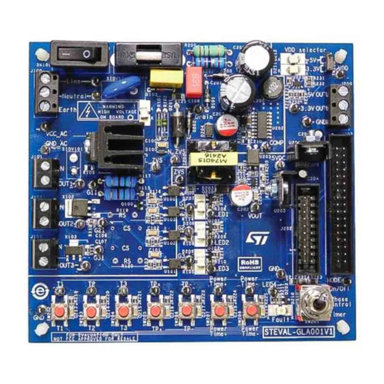
Figure 1.
STEVAL-GLA001V1 evaluation board (top view)
UM2304 - Rev 3 - January 2019
www.st.com
For further information contact your local STMicroelectronics sales office.
Advertisement
Table of Contents

Subscribe to Our Youtube Channel
Related Manuals for STMicroelectronics STEVAL-GLA001V1


Summary of Contents for STMicroelectronics STEVAL-GLA001V1
-
Page 1: Figure 1. Steval-Gla001V1 Evaluation Board (Top View)
Once you have installed the relevant firmware (freely available at STSW-GLA001V1) on the NUCLEO-F030R8 development board, you can start adjusting the main parameters through a common serial interface like HyperTerminal. The STEVAL-GLA001V1 evaluation board features a wide input voltage range, low standby power losses, IEC61000-4-4 robustness and two low voltage power supplies. -
Page 2: Evaluation Board Objectives
On the smart control side, using an STM32 Nucleo board (NUCLEO-F030R8) with the available firmware allows to easily configure a lot of parameters for specific load control. STEVAL-GLA001V1 evaluation board main blocks STEVAL-GLA001V1 evaluation board features the following main components: •... -
Page 3: Targeted Applications
UM2304 Targeted applications Figure 2. STEVAL-GLA001V1 evaluation board synoptic Power supply insulated secondary side 5V/ 3.3V supply for µC and insulated gate control 5VDC AC switches and load connections Mains in put LDO 5 V LDO 3.3 V selector Inpu t switch... -
Page 4: Performance
Performance Performance STEVAL-GLA001V1 evaluation board performance characteristics include: • Stand-by losses < 300 mW (@ 240 V) • IEC 61000-4-4 (STEVAL-GLA001V1 evaluation board with NUCLEO-F030R8 development board): – 2 kV criteria A – 4 kV criteria B AC switch load capability... -
Page 5: Getting Started
This evaluation board must be used in a suitable laboratory by qualified personnel who are familiar with the installation, use and maintenance of power electrical systems. The STEVAL-GLA001V1 evaluation board is designed for demonstration purposes only, and shall not be used either for domestic or industrial installations. -
Page 6: Board Connection
• J200: supplies insulated low voltage 5 V and 3.3 V power (if required), complying with power supply output capability (refer to Section 1.2 STEVAL-GLA001V1 evaluation board main blocks). 1. Caution: Do not connect mains voltage. STEVAL-GLA001V1 evaluation board start-up... -
Page 7: Hardware Function Description
2.5.1 Power supply: primary side The power supply primary side includes the following components: • SW100 switch to turn the STEVAL-GLA001V1 evaluation board on or off • F100 fuse and SIOV100 varistor for board protection • C109 capacitor for noise immunity •... -
Page 8: Power Supply: Secondary Side
UM2304 Hardware function description Figure 7. STEVAL-GLA001V1 evaluation board power supply primary side components SIOV100 F100 High Voltage SW100 C109 Mains voltage D102 test point Auxiliary voltage test point “Line” and “Neutral” test points are available to measure mains voltage. -
Page 9: Push Buttons
Hardware function description Figure 9. STEVAL-GLA001V1 evaluation board VDD selector components For a 3.3 V compatible microcontroller, VDD must be connected to 3.3 V by setting the SW200 jumper to the bottom (D211 LED lights up); this is the default position. -
Page 10: Switch Mode
Hardware function description Figure 11. STEVAL-GLA001V1 evaluation board LED components If the LEDx signal is set to 0 (GND), the chosen LED is OFF; if the LEDx signal is set to 5 V, 3.3 V or VDD, the chosen LED is illuminated. -
Page 11: Gate Control: Primary Side (High Voltage)
AC switch performance. Figure 13. STEVAL-GLA001V1 evaluation board AC switch gate control (primary side) components “VCC_AC”, “GND_AC”, “OUT1”, “G1I”, “OUT2”, “G2I”, “OUT3” and “G3I” tests points are available to measure auxiliary voltage, AC switches output and gate voltage level. -
Page 12: Zvs
« L_ZVS ») ZVS signal (« ZVS » regarding « GND ») Figure 16. STEVAL-GLA001V1 evaluation board ZVS components From the primary side, “Line”, “Neutral”, “N_ZVS” and “L_ZVS” test points are available to measure ZVS voltage level. Caution: These test points are referenced to high voltage. -
Page 13: Evaluation Board Operation With Stm32 Nucleo Board
User board Ribbon cable 2nd way: use user board with user microcontroller to control the STEVAL-GLA001V1 To use the STEVAL-GLA001V1 with the NUCLEO-F030R8 the latter must first be programmed with the firmware you can download from the STSW-GLA001V1 web page (for detailed instructions, refer to the firmware user manual). -
Page 14: Triac Control
UM2304 Triac control Triac control A Triac or AC switch can be controlled through a DC or pulse gate command. If you apply a gate current until the Triac current exceeds I (latching current), the Triac remains ON even if the gate current is removed. The Triac turns OFF when the Triac current reaches zero, if the gate control is released. -
Page 15: Figure 20. On/Off Control In Basic Mode (Dc Command On The Left And Pulse Command On The Right)
UM2304 Operating mode 3.3.2 ON/OFF basic mode Figure 20. ON/OFF control in basic mode (DC command on the left and pulse command on the right) push push push push Triac push Triac push button button tp tp Triac gate Triac gate command command Wait for next zero voltage crossing... -
Page 16: On/Off Timer Mode
UM2304 Operating mode 3.3.3 ON/OFF timer mode Figure 21. ON/OFF control in timer mode (DC command on the left and pulse command on the right) push push Triac push Triac push button button OnTime OnTime tp tp Triac gate Triac gate command command Wait for next zero voltage crossing... -
Page 17: Figure 22. Phase Control (Zoom On The Right)
UM2304 Operating mode 3.3.4 Phase control mode Figure 22. Phase control (zoom on the right) push push Triac push td tp button Triac gate MainsPeriod/2 command MainsPeriod tp = Wait for next zero voltage crossing MainsPeriod MAINS Current in the Triac turns off at next zero current cros sing... -
Page 18: Zvs Function
“Final value” entered in “td_zvs” should be the difference between the “td_zvs” delay and the inductive load delay. For example, “td_zvs” due to the STEVAL-GLA001V1 is 1000 µs, and inductive load delay is 2500 µs: the final value is “td_zvs” – “inductive load delay” = 1000 – 2500 = –1500 µs. -
Page 19: Fault Led
The firmware is able to manage ZVS circuit presence: according to the “zvs_hw” parameter value, some mode operations may or may not be available. With the STEVAL-GLA001V1, the ZVS parameter is activated by default. In case of firmware re-use with user-own design, ZVS function could be deactivated.. -
Page 20: Table 4. Readable Parameters
UM2304 User interface Figure 28. User interface list of commands The commands perform the following functions: • read board state and configuration parameters • set configuration parameters • start and stop AC switches • store configurations • restore configuration to factory settings Table 4. -
Page 21: Table 5. Configurable Parameters
UM2304 User interface Name Description Unit OnTime Timer duration (for timer mode) Step for increasing or decreasing OnTime_step OnTime Margin before next cycle (for phase ZCS margin µs control mode) System State State of the STEVAL board Fault Code Information about board error Table 5. -
Page 22: Evaluation Board Operation Without Stm32 Nucleo Board
Evaluation board operation without STM32 Nucleo board User connector inputs and outputs If you wish to connect the STEVAL-GLA001V1 evaluation board to your own-board embedding another microcontroller, refer to the following figure and table for details regarding the signal type of each pin. -
Page 23: Mode Switch Voltage
UM2304 MODE switch voltage Pin no. Name Description Type from user side Voltage level 3.3 V power supply (to 3.3 V referenced to 3.3VDC Power supply supply user board) LED2 LED n°2 command Output VDD/GND 5 V power supply (to 5VDC Power supply 5 V referenced to GND... -
Page 24: Schematic Diagrams
UM2304 Schematic diagrams Schematic diagrams Figure 30. STEVAL-GLA001V1 - AC input TP100 SW100 SW KEY-SPST/10A F100 N_inp FUSE 10A/250V C108 68nF/275Vac/X2 C109 SIOV100 R121 10nF/275Vac/X2 S14K300/EPC 3.3k/0.5W D103 D101 D102 BZX79C2V4 red LED 1N4007 L_inp TP105 J100 N_inp L_inp conn_3pts Figure 31. -
Page 25: Figure 32. Steval-Gla001V1 - Triac Gate Control
UM2304 Schematic diagrams Figure 32. STEVAL-GLA001V1 - Triac gate control TP114 VCC_AC TP115 U103 R112 R113 TLP187 R114 R117 R115 C103 10nF 150 / 2W 150 / 2W Q100 TP117 SMBTA42 R116 C104 4.7k GND_AC TP110 TP109 U102 R106 R107... -
Page 26: Figure 34. Steval-Gla001V1 - Power Supply
Q200 Q201 Q202 Q203 LED1 LED2 LED3 LED4 2N7002 2N7002 2N7002 2N7002 R215 R218 R216 R217 Figure 36. STEVAL-GLA001V1 - Commands/parameters push buttons R220 R221 R222 R219 TP219 TP220 TP221 TP222 C213 C214 C215 C216 SW202 SW203 SW204 SW205 10nF... -
Page 27: Figure 37. Steval-Gla001V1 - Mode Selector Switch
UM2304 Schematic diagrams Figure 37. STEVAL-GLA001V1 - Mode selector switch TP212 MODE SW201 SW DPDT 3 POS MODE R212 R213 R214 Figure 38. STEVAL-GLA001V1 - Customer board connector J202 LED1 MODE LED3 3.3VDC LED2 5VDC Power/Time+ Power/Time- LED4 CON20A Figure 39. -
Page 28: Bill Of Materials
UM2304 Bill of materials Bill of materials Table 7. STEVAL-GLA001V1 bill of materials Item Q.ty Ref. Part/Value Description Manufacturer Order code C100, C101, C102, C103, 10 nF 50 V min C213, C214, Ceramic ±10% SMD C215, C216, capacitor 1206 C217, C218,... - Page 29 UM2304 Bill of materials Item Q.ty Ref. Part/Value Description Manufacturer Order code 150 n 16 V min Ceramic C211 ±10% SMD capacitor 0805 BAT48Z 350 D100, D205 mA min 40 V Diodes min SOD-123 1N4007 1 A min D101, D200 1000 V min Diodes DO-41...
- Page 30 UM2304 Bill of materials Item Q.ty Ref. Part/Value Description Manufacturer Order code 560 1/2 W min R103, R104 Resistors ±5% SMD 0805 R105, R108, R112, R113, 1 k 1/8 W min Resistors R212, R214, ±5% SMD 0805 R228 374 1/2 W min R106, R107 Resistors ±5% SMD 0805...
- Page 31 UM2304 Bill of materials Item Q.ty Ref. Part/Value Description Manufacturer Order code S14K300 300 Vac diameter 14 SIOV100 mm pitch 7.62 SIOV101 Not connected SW100 Switch 10 A SPST Arcolectric H8800VACL13 3 points header 3 contact SW200 pitch 2.54 mm header Switch 3 SW201...
- Page 32 UM2304 Bill of materials Item Q.ty Ref. Part/Value Description Manufacturer Order code M3 Lenght 6 Screw M3 Screw M3 Lenght 2 Nut M3 M4 Lenght 2 Support stand Board support with lock 10 A / 250 V 5 x Fuse Fuse 20 mm Female...
-
Page 33: Steval-Gla001V1 Silkscreen Top
UM2304 STEVAL-GLA001V1 silkscreen TOP STEVAL-GLA001V1 silkscreen TOP Figure 40. STEVAL-GLA001V1 silkscreen TOP UM2304 - Rev 3 page 33/46... -
Page 34: Test Points
UM2304 Test points Test points Table 8. Test points Voltage reference Name Description Line Mains voltage line Neutral Mains voltage neutral (after input switch and fuse) Drain Viper drain L_ZVS Line on optocoupler for ZVS function N_ZVS Neutral on optocoupler for ZVS function COMP Viper comp pin VCC_AC... -
Page 35: Ac Switch Gate Control Dimensioning
AC switch datasheet. This parameter is temperature dependent, so recalculation is required if a parameter like ambient temperature changes. STEVAL-GLA001V1 evaluation board embeds three AC switches and all gate control circuits have been calculated to ensure turn-on for ambient temperature from 0 to 60 °C. It also takes into account fluctuation on VCC_AC voltage (non-regulated auxiliary voltage referenced to mains voltage) from approximatively 13 V to 21 V. -
Page 36: Figure 42. Acst310-8B Datasheet Extract
UM2304 AC switch gate control dimensioning Figure 42. ACST310-8B datasheet extract At 0 °C ambient temperature, I * 1.4 = 14 mA is required to ensure Triac activation. Gate-cathode resistor (R V GT = R110) current should be considered in the calculation as it is significant. In this case, the required I I G min = + 14 mA = + 14 mA = 19 mA... - Page 37 UM2304 AC switch gate control dimensioning V GT I G min = + 14 mA = + 8 mA = 12.5 mA R111 V R103 + R104 V CC_AC min + V GT max − V CEsat 13 + 1 − 0.3 Considering this current value and the VCC_AC minimum voltage, the gate resistor calculation is: R103 + R104 = = 1096 Ω...
-
Page 38: Steval-Gla001V1 Power Losses
• Tamb = 22 °C • VDD = 5 V (worst case) • MODE switch in On/off position (worst case) Table 9. Typical STEVAL-GLA001V1 standby losses Vmains I(input) P(input) 240 V / 60 Hz 10 mA 288 mW UM2304 - Rev 3... -
Page 39: Iec61000-4-4 Performance
Vmains = 230 Vrms / 50 Hz • Tamb = 22 °C • STM32 Nucleo board connected and supplied by STEVAL-GLA001V1 • 5 kHz - burst duration = 15 ms and repetitive burst period = 300 ms • 100 kHz - burst duration = 0.75 ms and repetitive burst period = 300 ms •... -
Page 40: Ac Switch Performance Improvements
UM2304 AC switch performance improvements AC switch performance improvements You can improve AC switch performance in several ways, such as adding a snubber, a R or a varistor. The following table summarizes the configurations. Table 11. Tips for AC switch performance improvement IEC61000-4-5 or AC switch IEC61000-4-4 or dV/dt... -
Page 41: Revision History
UM2304 Revision history Table 12. Document revision history Date Version Changes 04-Dec-2017 Initial release. 23-Mar-2018 Minor text changes. Minor text and formatting changes. 24-Jan-2019 Updated Section 6 Bill of materials. UM2304 - Rev 3 page 41/46... -
Page 42: Table Of Contents
STEVAL-GLA001V1 evaluation board main blocks ........2... - Page 43 STEVAL-GLA001V1 silkscreen TOP ........
- Page 44 Typical STEVAL-GLA001V1 standby losses ........
- Page 45 STEVAL-GLA001V1 evaluation board VDD selector components ....... . . 9...
- Page 46 IMPORTANT NOTICE – PLEASE READ CAREFULLY STMicroelectronics NV and its subsidiaries (“ST”) reserve the right to make changes, corrections, enhancements, modifications, and improvements to ST products and/or to this document at any time without notice. Purchasers should obtain the latest relevant information on ST products before placing orders. ST products are sold pursuant to ST’s terms and conditions of sale in place at the time of order acknowledgement.
Need help?
Do you have a question about the STEVAL-GLA001V1 and is the answer not in the manual?
Questions and answers