Table of Contents
Advertisement
Quick Links
UM1521
User manual
STM32L152D-EVAL
evaluation board
Introduction
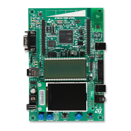
The STM32L152D-EVAL evaluation board is a complete demonstration and development
platform for STMicroelectronic's ARM cortex-M3 core-based STM32L152ZDT6
microcontroller featuring two I2C, three SPI, five USART, 12-bit ADC, 12-bit DAC, LCD
driver, internal 48 KB SRAM and 384 KB Flash, touch sensing, USB FS, LCD controller,
FSMC and JTAG debugging support.
This board can be used as reference design for user application development but it is not
considered as final application. The full range of hardware features on the board helps you
evaluate all peripherals (USB FS, USART, audio DAC, microphone ADC, dot-matrix LCD,
LCD glass, IrDA, LDR, SRAM, NOR Flash, MicroSD Card, temperature sensor and so on)
and develop your own applications. Extension headers make it possible to easily connect a
daughterboard or wrapping board for your specific application.
An ST-LINK/V2 is integrated on the board as embedded in-circuit debugger and
programmer for the STM32 MCU.
Figure 1.
STM32L152D-EVAL evaluation board
March 2012
Doc ID 022868 Rev 1
1/56
www.st.com
www.BDTIC.com/ST
Advertisement
Table of Contents

Related Manuals for STMicroelectronics STM32L152D-EVAL


Summary of Contents for STMicroelectronics STM32L152D-EVAL
-
Page 1: 2/56 Doc Id 022868 Rev
STM32L152D-EVAL evaluation board Introduction The STM32L152D-EVAL evaluation board is a complete demonstration and development platform for STMicroelectronic's ARM cortex-M3 core-based STM32L152ZDT6 microcontroller featuring two I2C, three SPI, five USART, 12-bit ADC, 12-bit DAC, LCD driver, internal 48 KB SRAM and 384 KB Flash, touch sensing, USB FS, LCD controller, FSMC and JTAG debugging support. -
Page 2: Table Of Contents
Contents UM1521 Contents Overview ..........4 Features . - Page 3 Schematics ..........35 Appendix A STM32L152D-EVAL I/O assignment ......49 Appendix B Mechanical dimensions.
-
Page 4: Overview
For more information and to download the latest version available, please refer to the STM32L152D-EVAL demonstration software available on www.st.com. Order code To order the STM32L152ZDT6 evaluation board, use the order code STM32L152D-EVAL. 4/56 Doc ID 022868 Rev 1 www.BDTIC.com/ST... -
Page 5: Delivery Recommendations
UM1521 Overview Delivery recommendations Some verifications are needed before using the board for the first time to make sure that nothing was damaged during shipment and that no components are unplugged or lost. When the board is extracted from its plastic bag, please check that no component remains in the bag. -
Page 6: Hardware Layout And Configuration
TQFP package). The hardware block diagram Figure 2 illustrates the connection between STM32L152D-EVAL and peripherals (LCD glass, Color LCD, Touch slider, USB FS connector, Temperature Sensor, USART, IrDA, Audio, SRAM, Nor Flash, EEPROM,RF EEPROM, MicroSD Card and embedded ST-LINK) and... - Page 7 UM1521 Hardware layout and configuration Figure 3. Hardware block diagram Doc ID 022868 Rev 1 7/56 www.BDTIC.com/ST...
-
Page 8: Development And Debug Support
Hardware layout and configuration UM1521 Development and debug support Version 2 of the ST-LINK called ST-LINK/V2 is embedded on the board. This tool allows program loading and debugging on the STM32L using a JTAG or SWD interface. Third-party debug tools are also supported by JTAG connector CN16 and Trace connector CN11. A specific driver must be installed on your PC for communication with embedded ST- LINK/V2. -
Page 9: Power Supply
Hardware layout and configuration Power supply The STM32L152D-EVAL evaluation board is designed to be powered by a 5 V DC power supply and to be protected by PolyZen from a wrong power plug-in event. It is possible to configure the evaluation board to use any of following four sources for the power supply. - Page 10 Hardware layout and configuration UM1521 Table 2. Power supply jumper settings (continued) Jumper Description Setting VDD is connected to fixed +3.3 V DC power when JP5 is set as shown to the right: (Default setting) VDD is connected to adjustable DC power from 1.65 V to 3.6 V when JP5 is set as shown to the right: VDD power is directly connected to MCU VDD when JP10 is set as shown to the right (Default setting):...
-
Page 11: Clock Source
PC15 is connected to extension connector CN5 when SB7 is closed. In such case R84 must be removed to avoid disturbance due to the 32 KHz quartz Reset source The reset signal of the STM32L152D-EVAL evaluation board is low active and the reset sources include: ●... -
Page 12: Boot Option
Boot related switch Switch Switch Boot from configuration STM32L152D-EVAL boots from user Flash when SW1 is set as 0 <----> 1 shown to the right. SW2 is don't care in this configuration. (Default setting) 0 <----> 1 STM32L152D-EVAL boots from embedded SRAM when SW1 and SW2 are set as shown to the right. -
Page 13: Lcd Glass Module
Hardware layout and configuration LCD glass module An LCD glass module daughterboard (MB979) is mounted on the STM32L152D-EVAL evaluation board. It can be connected to the LCD driver of the STM32L152ZDT6 or work as a set of jumpers by mounting it on two possible positions; position "IO" or position "LCD": ●... - Page 14 Hardware layout and configuration UM1521 Table 8. LCD glass related jumpers Jumper Description Setting PA1 is connected to microphone ( MIC_INP signal) when JP8 is set as shown to the right: (Default setting) PA1 is connected to LCD glass as SEG0 when JP8 is set as shown to the right: PA2 is connected to microphone (MIC_INN signal)when JP6 is set as shown to the right: (Default setting) PA2 is connected to LCD glass as SEG1 when JP6 is set as shown to the right:...
- Page 15 UM1521 Hardware layout and configuration Table 11. LCD glass segments mapping table pins 25-36 COM1 7J COM2 7C COM3 7B COM4 7I COM5 19a COM6 19b COM7 S µA COM8 nA Table 12. LCD glass segments mapping table pins 37-48 COM1 3N COM2 3M COM3 3H...
- Page 16 Hardware layout and configuration UM1521 Figure 6. LCD segment names 16/56 Doc ID 022868 Rev 1 www.BDTIC.com/ST...
-
Page 17: Audio
UM1521 Hardware layout and configuration Audio The STM32L152D-EVAL evaluation board supports stereo audio play by using an audio DAC CS43L22 connected to both I2S2 port and one channel of DAC in the microcontroller STM32L152ZDT6. ● OpAmp3 of the STM32L152ZDT6 acts as a low pass filter of audio output for this DAC. - Page 18 Hardware layout and configuration UM1521 Figure 7. R39 resistor placement Note: If Bootloader_RESET signal is not used, remove R39 to avoid disturbance due to CTS signal from pin8 of CN1, which could cause MCU reset with some software. Table 14. RS-232 &...
-
Page 19: Touch Sensing Slider
Hardware layout and configuration 2.10 Touch sensing slider The STM32L152D-EVAL evaluation board supports a touch sensing slider based on either RC charging or charge transfer technology. The charge transfer technology is enabled by default assembly. PB6 and PB7 manage an active shield reducing sensitivity to other signals. The active shield is placed on an internal layer immediately under the slider (layer 2) to cover components related to the slider and the slider itself. -
Page 20: Serial Eeprom
Hardware layout and configuration UM1521 2.12 Serial EEPROM A 4 Kbit (M95040-R) serial EEPROM is connected to SPI1 of the STM32L152ZDT6. Serial Flash chip select is managed by I/O pin PB0. The EEPROM will work properly when VDD > 1.8 V. The LCD glass module has to be mounted on IO position for SPI EEPROM usage. -
Page 21: Analog Input
Comparator non-inverting input PB5; connected to potentiometer (RV3) used as analog voltage input for comparison with internal voltage reference (for instance Band gap) in order to test analog Wakeup feature of the MCU. Figure 8. STM32L152D-EVAL comparator features Doc ID 022868 Rev 1 21/56 www.BDTIC.com/ST... -
Page 22: Temperature Sensor
Hardware layout and configuration UM1521 Table 18. Comparator, LDR and potentiometer related jumpers Jumper Description Setting PB4 is connected to LDR_OUT when JP2 is set as shown to the right: PB4 is connected to TRST when JP2 is set as shown to the right: (Default setting). -
Page 23: Display And Input Devices
UM1521 Hardware layout and configuration 2.19 Display and input devices The display devices are 4 general purpose color LED's (LD 1,2,3,4) and a 240x320 TFT color LCD connected to bank3 of the STM32L152ZDT6 FSMC interface port. The LCD glass module must be mounted on IO position for color LCD usage. Refer to Section 2.6: LCD glass module for detail. -
Page 24: Idd Measurement
The built-in I measurement circuit implemented allows the consumption measurement of the STM32L152ZDT6 while the MCU is in Run or Low power saving modes. For I measurement the circuit below is implemented on the STM32L152D-EVAL. Figure 9. STM32L152D-EVAL I measurement circuit 2.20.1... -
Page 25: Ibias Current Measurement Procedure
UM1521 Hardware layout and configuration Figure 10. STM32L152D-EVAL I Low power modes measurement timing diagram Wake-up measurement period Wake-up Clear CNT event event MCU mode Low power IDD_CNT_EN (PC13) Q12 = LOW_POWER_EN (T1 pin 3) Q13 = IDD_WAKEUP (PA0) Q13n = disconnect filter... -
Page 26: Connectors
RS-232_RX (PB11) RS-232_TX (PB10) Bootloader_RESET Power connector CN2 The STM32L152D-EVAL evaluation board can be powered from a DC 5 V power supply via the external power supply jack (CN2) shown in Figure 12. The central pin of CN2 must be positive. -
Page 27: Daughterboard Extension Connector Cn5 And Cn10
Daughterboard extension connector CN5 and CN10 Two 42-pin male headers CN5 and CN10 can connect the daughterboard (or standard wrapping board) to the STM32L152D-EVAL evaluation board. All GPIOs are available on them and the LCD glass connectors (CN6, CN7). The space between these two connectors and positions of POWER, GND and RESET pins are defined as a standard which allows common daughterboards to be developed for several evaluation boards. - Page 28 Connectors UM1521 Table 22. Daughterboard extension connector CN5 (continued) How to disconnect with function block on Pin Description Alternative function STM32L152D-EVAL board FSMC_A4 FSMC_A2 FSMC_A0 FSMC_A20 / TRACED1 Remove R147 PF10 POTENTIOMETER JP13 pin5,6 open IDD_WAKEUP / Remove R118 KEY_TAMPER2 /WKUP1...
- Page 29 UM1521 Connectors Table 23. Daughterboard extension connector CN10 (continued) How to disconnect with function block on Pin Description Alternative function STM32L152D-EVAL board FSMC_D3 OSC_IN Remove X1 from socket and close SB2 PA14 JTCK/SWCLK FSMC_A22 PA12 USB_DP Remove R136 PA11 USB_DM...
-
Page 30: Lcd Glass Daughterboard Connectors Cn6 And Cn7
Connectors UM1521 LCD glass daughterboard connectors CN6 and CN7 Two 48-pin male headers CN6 and CN7 connect the LCD glass daughterboard (MB979). GPIOs which act as LCD glass signals and are not on CN5 and CN10 are available on these two connectors. -
Page 31: St-Link/V2 Programming Connector Cn9
UM1521 Connectors ST-LINK/V2 programming connector CN9 Connector CN9 is used only for embedded ST-LINK/V2 programming during board manufacture. It is not populated by default and is not for end-user use. ST-LINK/V2 USB type B connector CN14 The USB connector CN14 is used to connect the embedded ST-LINK/V2 to a PC for debugging the board. -
Page 32: Trace Debugging Connector Cn11
TDO/PB3 TDI/PA15 RESET# TraceCLK/PE2 TraceD0/PE3 or SWO/PB3 TraceD1/PE4 or nTRST/PB4 TraceD2/PE5 TraceD3/PE6 3.10 Audio jack CN13 A 3.5 mm stereo audio jack CN13 connected to audio DAC is available on the STM32L152D-EVAL board. 32/56 Doc ID 022868 Rev 1 www.BDTIC.com/ST... -
Page 33: Microsd Connector Cn3
UM1521 Connectors 3.11 MicroSD connector CN3 Figure 16. MicroSD connector CN3 (viewed from above PCB) Table 28. MicroSD connector CN3 Description Description SDIO_D2(PC10) Vss/GND SDIO_D3(PC11) SDIO_D0(PC8) SDIO_CMD(PD2) SDIO_D1(PC9) SDIO_CLK(PC12) MicroSDcard_detect (PC7) 3.12 Analog input-output 2-pin connector CN8 Figure 17. Analog input-output connector CN8 (viewed from top) Table 29. -
Page 34: User Usb Type B Connector Cn15
Connectors UM1521 3.13 User USB type B connector CN15 Figure 18. USB type B connector CN15 (viewed from front) Table 30. USB type B connector CN15 Description Description VBUS (power) Shield 3.14 RF EEPROM daughterboard connector CN12 Figure 19. RF EEPROM daughterboard connector CN12 (viewed from front) Table 31. -
Page 35: Schematics
UM1521 Schematics Schematics Figure 20. STM32L152D-EVAL Doc ID 022868 Rev 1 35/56 www.BDTIC.com/ST... - Page 36 Schematics UM1521 Figure 21. Audio 36/56 Doc ID 022868 Rev 1 www.BDTIC.com/ST...
- Page 37 UM1521 Schematics Figure 22. Extension connector Doc ID 022868 Rev 1 37/56 www.BDTIC.com/ST...
- Page 38 Schematics UM1521 Figure 23. I measurement 38/56 Doc ID 022868 Rev 1 www.BDTIC.com/ST...
- Page 39 UM1521 Schematics Figure 24. JTAG and Trace Doc ID 022868 Rev 1 39/56 www.BDTIC.com/ST...
- Page 40 Schematics UM1521 Figure 25. RS-232 and LCD 40/56 Doc ID 022868 Rev 1 www.BDTIC.com/ST...
- Page 41 UM1521 Schematics Figure 26. MCU Doc ID 022868 Rev 1 41/56 www.BDTIC.com/ST...
- Page 42 Schematics UM1521 Figure 27. MicroSD Card 42/56 Doc ID 022868 Rev 1 www.BDTIC.com/ST...
- Page 43 UM1521 Schematics Figure 28. Peripherals Doc ID 022868 Rev 1 43/56 www.BDTIC.com/ST...
- Page 44 Schematics UM1521 Figure 29. Power 44/56 Doc ID 022868 Rev 1 www.BDTIC.com/ST...
- Page 45 UM1521 Schematics Figure 30. SRAM Flash Doc ID 022868 Rev 1 45/56 www.BDTIC.com/ST...
- Page 46 Schematics UM1521 Figure 31. ST_LINK 46/56 Doc ID 022868 Rev 1 www.BDTIC.com/ST...
- Page 47 UM1521 Schematics Figure 32. EEPROM and temperature sensor Doc ID 022868 Rev 1 47/56 www.BDTIC.com/ST...
- Page 48 Schematics UM1521 Figure 33. Touch slider 48/56 Doc ID 022868 Rev 1 www.BDTIC.com/ST...
-
Page 49: Appendix A Stm32L152D-Eval I/O Assignment
UM1521 STM32L152D-EVAL I/O assignment Appendix A STM32L152D-EVAL I/O assignment Table 32. STM32L152D-EVAL I/O assignment Pin No. Pin name STM32L152D-EVAL I/O assignment SEG 38 / A23 / TRACECK SEG 39 / A19 / TRACED0 A20 / TRACED1 A21 / TRACED2 TAMPER3/TRACED3 / WKUP3/U5V_DET... - Page 50 STM32L152D-EVAL I/O assignment UM1521 Table 32. STM32L152D-EVAL I/O assignment (continued) Pin No. Pin name STM32L152D-EVAL I/O assignment VDDA VDDA PA0WKUP IDD_WAKEUP / KEY_TAMPER2/WKUP1 SEG0 / Micro_OA1_INP SEG1 / Micro_OA1_INN SEG2 / Micro_OA1_OUT VSS_4 VDD_4 CON_ADC4 -DAC1 / Audio_DAC_OUT E2P_SCK SEG3 / ADJ_G_OA2_INP...
- Page 51 UM1521 STM32L152D-EVAL I/O assignment Table 32. STM32L152D-EVAL I/O assignment (continued) Pin No. Pin name STM32L152D-EVAL I/O assignment PE15 D12 / E2P_ MOSI PB10 SEG10 PB11 SEG11 VSS_1 VDD_1 PB12 SEG12 / I2S2_WS PB13 SEG13 / I2S2_CK PB14 SEG14 PB15 SEG15 / I2S2_SD...
- Page 52 STM32L152D-EVAL I/O assignment UM1521 Table 32. STM32L152D-EVAL I/O assignment (continued) Pin No. Pin name STM32L152D-EVAL I/O assignment PA11 USB_DM PA12 USB_DP PA13 JTMSSWDAT VSS_2 VDD_2 PA14 JTCKSWCLK PA15 SEG17 / JTDI PC10 COM4 / SEG28/ SEG40 / uSD_D2 PC11 COM5 / SEG29 /SEG41 / uSD_D3...
- Page 53 UM1521 STM32L152D-EVAL I/O assignment Table 32. STM32L152D-EVAL I/O assignment (continued) Pin No. Pin name STM32L152D-EVAL I/O assignment BOOT0 BOOT0 SEG16 / AUDIO_RF_Temp_SCL COM3 / AUDIO_RF_Temp_SDA SEG36 / BLN0 SEG37 / BLN1 VSS_3 VDD_3 Doc ID 022868 Rev 1 53/56 www.BDTIC.com/ST...
-
Page 54: Appendix B Mechanical Dimensions
Mechanical dimensions UM1521 Appendix B Mechanical dimensions Figure 34. Mechanical dimension > > Table 33. Mechanical dimensions Symbol Size (mm) Symbol Size (mm) Symbol Size (mm) 68.58 72.363 84.455 2.54 115.247 2.54 24.13 2.54 5.715 26.67 17.78 5.715 24.792 17.145 114.3 20.32 172.72... -
Page 55: Revision History
UM1521 Revision history Revision history Table 34. Document revision history Date Revision Changes 30-Mar-2012 Initial release. Doc ID 022868 Rev 1 55/56 www.BDTIC.com/ST... - Page 56 Please Read Carefully: Information in this document is provided solely in connection with ST products. STMicroelectronics NV and its subsidiaries (“ST”) reserve the right to make changes, corrections, modifications or improvements, to this document, and the products and services described herein at any time, without notice.
Need help?
Do you have a question about the STM32L152D-EVAL and is the answer not in the manual?
Questions and answers