Compaq AlphaServer DS20E Reference Manual
Hide thumbs
Also See for AlphaServer DS20E:
- Technical manual (16 pages) ,
- Reference manual (280 pages) ,
- Reference manual (300 pages)
Table of Contents
Advertisement
Quick Links
Advertisement
Table of Contents
Troubleshooting

Related Manuals for Compaq AlphaServer DS20E


Summary of Contents for Compaq AlphaServer DS20E
- Page 1 All manuals and user guides at all-guides.com AlphaServer DS20E AlphaStation DS20E Reference Guide Order Number: ER-K8F6W-UA. D01 This manual is for managers and operators of Compaq AlphaServer DS20E / AlphaStation DS20E systems. Compaq Computer Corporation...
- Page 2 The Open Group in the U.S. and other countries. All other product names mentioned herein may be trademarks of their respective companies. Compaq shall not be liable for technical or editorial errors or omissions contained herein. The information in this document is subject to change without notice.
-
Page 3: Table Of Contents
All manuals and user guides at all-guides.com Contents Preface ........................xi Chapter 1 System Overview System Enclosures ................1-2 System Parts (Front/Side View)............1-4 System Parts (Rear View) ..............1-6 Operator Control Panel................. 1-8 System Board ..................1-10 Server Feature Module ............... 1-12 PCI Slots ..................... - Page 4 All manuals and user guides at all-guides.com Installing the System Chassis............. 3-16 Installing the Interlock System ............3-18 3.10 Installing the Cable Management Arm ..........3-20 3.11 Dressing the Cables ................3-22 3.12 Attaching the Front Bezel..............3-24 Chapter 4 Booting and Installing an Operating System Setting Boot Options ................
- Page 5 All manuals and user guides at all-guides.com 5.12 Installing a Tape Drive ............... 5-35 5.13 External SCSI Expansion ..............5-37 5.14 AlphaBIOS Configuration Utilities............. 5-38 5.15 Updating Firmware ................5-41 5.15.1 Sources of Firmware Updates............5-42 5.15.2 Updating Firmware from the CD-ROM........5-43 Chapter 6 Remote Management Console RMC Overview ..................
- Page 6 All manuals and user guides at all-guides.com 7.18 Reading a File ..................7-38 7.19 Configuring a PCI NVRAM Module............ 7-40 7.20 Creating a Power-Up Script..............7-41 7.21 Loading AlphaBIOS ................7-43 7.22 Setting Console Security ..............7-44 7.22.1 Overview of Secure Mode.............. 7-44 7.22.2 Setting the Console Password............
- Page 7 All manuals and user guides at all-guides.com Chapter 9 Specifications Physical Specifications................9-2 Environmental Specifications ............... 9-4 Electrical Specifications ................ 9-5 Acoustical Data ..................9-7 Power Cord Requirements ..............9-8 9.5.1 General Requirements ..............9-8 9.5.2 Country-Specific Requirements ............9-9 Appendix A Regulatory and Safety Notices Class A and Class B Ratings..............A-1...
- Page 8 All manuals and user guides at all-guides.com Examples 4–1 Booting Tru64 UNIX from a Local SCSI Disk ........4-13 4–2 RIS Boot ....................4-16 4–3 Text-Based Installation Display ............4-18 4–4 Linux Boot Output ................4-21 4–5 Booting OpenVMS from the Local CD-ROM Drive......4-24 4–6 InfoServer Boot ...................
- Page 9 All manuals and user guides at all-guides.com Figures 1–1 DS20E System Variants ............... 1-2 1–2 System Parts ..................1-4 1–3 Ports and Connectors ................1-6 1–4 Control and Status Indicators............... 1-8 1–5 System Board ..................1-10 1–6 Server Feature Module ............... 1-12 1–7 PCI Slots (Rack Orientation) ..............
- Page 10 All manuals and user guides at all-guides.com 5–3 Removing Top Cover ................5-5 5–4 Memory Slot Locations................5-6 5–5 Installing DIMMs.................. 5-8 5–6 Removing DIMMs ................. 5-9 5–7 PCI Slots (Rack Orientation) .............. 5-11 5–8 Installing a PCI Option............... 5-12 5–9 Multichannel SCSI Installation ............
- Page 11 All manuals and user guides at all-guides.com 8–3 Troubleshooting Console-Reported Failures......... 8-5 8–4 Troubleshooting Boot Problems ............8-6 8–5 Operating System Reported Failures ........... 8-9 8–6 Troubleshooting Memory Problems ............ 8-10 9–1 Physical Specifications................9-2 9–2 Environmental Specifications ............... 9-4 9–3 Electrical Specifications ................
- Page 12 All manuals and user guides at all-guides.com...
-
Page 13: Preface
All manuals and user guides at all-guides.com Preface Intended Audience This manual is for managers and operators of Compaq AlphaServer DS20E / AlphaStation DS20E systems. WARNING: To prevent injury, access to internal components is limited to persons who have appropriate technical training and experience. - Page 14 All manuals and user guides at all-guides.com Chapter 4, Booting and Installing an Operating System, explains the SRM boot environment variables and gives examples of booting Tru64 UNIX, OpenVMS, and Linux. Chapter 5, Configuring and Installing Components, shows how to configure and install components such as memory DIMMs and PCI options.
- Page 15 All manuals and user guides at all-guides.com Information on the Internet Visit the following Compaq DS20E Web site for support resources for this system. http://www.compaq.com/alphaserver/ds_series.html Information and files for performing firmware updates is available at: ftp://ftp.digital.com/pub/Digital/Alpha/firmware/readme.html...
- Page 16 All manuals and user guides at all-guides.com...
-
Page 17: Chapter 1 System Overview
All manuals and user guides at all-guides.com Chapter 1 System Overview This chapter provides an overview of the AlphaServer/AlphaStation DS20E system, including: • System enclosures • System parts (front/side view) • System parts (rear view) • Operator control panel • System board •... -
Page 18: System Enclosures
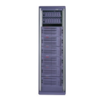
All manuals and user guides at all-guides.com System Enclosures The DS20E family consists of a standalone pedestal and a rackmount system. Figure 1–1 DS20E System Variants Rackmount Pedestal CAT0039 DS20E Reference Guide... - Page 19 All manuals and user guides at all-guides.com Enclosure The system is housed in an enclosure containing the system board, other logic modules, and two power supplies (maximum of three) with internal fans. The enclosure has bays for internal mass-storage devices, including a combination IDE CD-ROM/floppy disk drive, one available half-height removable bay, and either four 1.6-inch or six 1-inch hot-swap drive bays.
-
Page 20: System Parts (Front/Side View)
All manuals and user guides at all-guides.com System Parts (Front/Side View) Figure 1–2 identifies the main components of the system in a pedestal version. Components visible from the front and with the side panel removed are shown. Figure 1–2 System Parts CAT0151b DS20E Reference Guide... - Page 21 All manuals and user guides at all-guides.com Front Components Removable side cover Symbios SCSI adapter board System board CPU modules Server feature module Operator control panel (OCP) Removable media drive bay Combination CD-ROM/floppy drive Hard disk drives Door Power supplies Storage subsystem System Overview 1-5...
-
Page 22: System Parts (Rear View)
All manuals and user guides at all-guides.com System Parts (Rear View) Figure 1–3 shows the system ports and connectors on the rear of the chassis. Figure 1–3 Ports and Connectors CAT0019A DS20E Reference Guide... - Page 23 All manuals and user guides at all-guides.com Rear Components SCSI breakouts One shared 64-bit PCI/ 16-bit ISA slot Five 64-bit PCI slots AC power inlet Ethernet port Mouse port Keyboard port Universal serial bus (USB) (not supported) Serial port (COM1) Serial port (COM2) Parallel port System fan 0...
-
Page 24: Operator Control Panel
All manuals and user guides at all-guides.com Operator Control Panel The operator control panel provides system controls and status indicators. The controls are the Power, Halt, and Reset buttons. The panel has a green power LED, a yellow halt LED, and four diagnostic LEDs. - Page 25 All manuals and user guides at all-guides.com Power button. This button is a latching switch. Pressing the Power button on powers on the system. Pressing the button to standby turns off all DC voltages except Aux 5 volts. The 5 volt standby powers the remote management console (RMC).
-
Page 26: System Board
All manuals and user guides at all-guides.com System Board The system board contains slots for CPUs, memory DIMMs, and I/O options. Figure 1–5 System Board CAT0030 CPU slots (CPU0 is right slot) I/O slots Floppy Memory slots SCSI DS20E Reference Guide 1-10... - Page 27 All manuals and user guides at all-guides.com All memory and I/O components are located on a single system board that contains a memory subsystem, PCI bus, ISA bus, integrated SCSI fast/wide/Ultra I/O controllers, and option slots for PCI-based and ISA-based option modules.
-
Page 28: Server Feature Module
All manuals and user guides at all-guides.com Server Feature Module A separate server feature module (SFM) affixed to the system chassis monitors environmental conditions in the system. The SFM supports the two system fans and three power supplies and monitors the state of the CPU fans on the system board. - Page 29 All manuals and user guides at all-guides.com N+1 Fan Configuration The SFM supports and monitors the two system fans. For optimal cooling, both fans are always running. If one of the fans fails or is hot-swapped for servicing, the system continues to function with the other fan running at full speed. The fan thermostat is set to drive the fans at their minimum speed in environments below 26ºC to keep noise levels low.
-
Page 30: Pci Slots
All manuals and user guides at all-guides.com PCI Slots The system board has six, 64-bit PCI slots, one of which is a combination PCI/ISA slot. The callouts in Figure 1–7 show the PCI slot locations on the system board. Slot 1 supports a half-length card only. - Page 31 All manuals and user guides at all-guides.com The system uses a Cypress South Bridge chip (CY82C698), which is a highly integrated peripheral solution for PCI-based motherboards. It provides a bridge between the PCI bus, ISA bus, and the IDE peripherals. See Chapter 5 for information on installing PCI options.
-
Page 32: Power Supplies
All manuals and user guides at all-guides.com Power Supplies The system comes with two 375-watt power supplies that are connected in parallel. A third power supply can be added for redundancy. Power supply 0 (PS0) is the leftmost supply in a pedestal system and the topmost supply in a rackmount system. - Page 33 All manuals and user guides at all-guides.com A power backplane integrates the supplies for power distribution, monitoring, and control. The power supplies can be accessed and removed through the front of the enclosure. See Chapter 5 for instructions on adding or replacing a power supply.
-
Page 34: Removable Media Storage
All manuals and user guides at all-guides.com Removable Media Storage The removable media area contains the removable media bay, which accommodates one 5.25-inch, half-height tape device and a combination CD-ROM/FDD drive. Figure 1–9 Removable Media Storage CAT0050 Removable media bay CD-ROM drive FDD drive DS20E Reference Guide... -
Page 35: Hard Disk Drive Storage
All manuals and user guides at all-guides.com 1.10 Hard Disk Drive Storage The system comes with either a four-slot storage subsystem that holds 1.6-inch drives or a six-slot storage subsystem that holds 1.0-inch drives. Figure 1–10 shows the storage subsystems. Figure 1–10 Four-Slot and Six-Slot Storage Subsystems DVA00047b The storage system backplane contains on-board multimode terminators that... -
Page 36: Two-Way Combination Module
The combination module features 2D/3D video (with 4 MB VRAM), along with 10/100 MB Fast Ethernet. The module provides connections for the VGA (Video Permedia 2) and the Ethernet (NIC functions). You can order the module from Compaq. DS20E Reference Guide 1-20... -
Page 37: Console Terminal
All manuals and user guides at all-guides.com 1.12 Console Terminal The console terminal can be a serial (character cell) terminal connected to the COM1 port or a VGA monitor connected to a VGA adapter on PCI slot 1. When a VGA monitor is connected, a keyboard and mouse must also be connected. - Page 38 All manuals and user guides at all-guides.com...
-
Page 39: Chapter 2 Installing The Pedestal System
All manuals and user guides at all-guides.com Chapter 2 Installing the Pedestal System This chapter describes how to set up the pedestal system. It also gives instructions for converting a rackmount system to a pedestal system. The following topics are covered: •... -
Page 40: System Dimensions And Service Area
All manuals and user guides at all-guides.com System Dimensions and Service Area Figure 2–1 shows the system dimensions and the clearance needed to access the pedestal system for servicing. Figure 2–1 System Dimensions 44.8 cm (17.6 in) 74.7 cm (29.4 in) 22.1 cm (8.7 in) PK3212... -
Page 41: Power Requirements
All manuals and user guides at all-guides.com Power Requirements The system automatically detects the voltage source when it powers up, and adjusts the power supply input to accept that voltage. Figure 2–2 shows maximum current ratings for a fully loaded system (without monitor or terminal). -
Page 42: Shipment Box
All manuals and user guides at all-guides.com Shipment Box The pedestal system is shipped in a single box. The system chassis is completely assembled, with all modules installed. Instructions for unpacking are in the accessories tray . An installation document and this reference guide are also in the tray, along with other accessories. -
Page 43: Pedestal Setup
All manuals and user guides at all-guides.com Pedestal Setup Connect the cabling as shown in Figure 2–4. Figure 2–4 Cabling the System ENET CAT0017c AC power connector Mouse Keyboard Monitor Printer Modem with 10/100Base-T network cable connection , if option ordered Installing the Pedestal System 2-5... -
Page 44: System Access
All manuals and user guides at all-guides.com System Access The system has a key lock that is located on the front door to prevent unauthorized access. The removable media devices and the system control panel are accessible through an upper front door that opens by sliding down the lock latch as shown in Figure 2–5. -
Page 45: Installing A Pedestal Kit
All manuals and user guides at all-guides.com Installing a Pedestal Kit This section is for customers who ordered a pedestal kit. The pedestal kit is used to convert a rackmount system to a pedestal. CAUTION: The system is very heavy. Two people are needed to lift and maneuver it. -
Page 46: Pedestal Kit Contents
All manuals and user guides at all-guides.com Figure 2–6 Pedestal Kit Contents PKO980 DS20E Reference Guide... -
Page 47: Pedestal Kit Contents
All manuals and user guides at all-guides.com Table 2–1 Pedestal Kit Contents Hardware Part Number Quantity Upper panel 74-60248-01 Lower panel 74-60248-02 Slide feet 74-51716-01 2 (may already be installed on Side dress panel 74-60250-01 Side access cover 74-60247-02 (painted) Front door assembly 70-40254-01 Screws, M3x6mm... -
Page 48: Installing The Lower Panel
All manuals and user guides at all-guides.com Figure 2–7 Installing the Lower Panel PK3215 2-10 DS20E Reference Guide... - Page 49 All manuals and user guides at all-guides.com Conversion Procedure 1. Remove the top cover from the rack system by loosening the captive screw and sliding the cover to the rear. Set aside the cover; it will not be reused. 2. Rotate the system chassis so that the operator control panel (OCP) is at the lower right.
-
Page 50: Installing The Upper Panel
All manuals and user guides at all-guides.com 5. Place the upper panel with the painted surface up and the large tabs to the left on the top of the unit. Slide the panel to the right. Insert a thumbscrew into the tab on the panel and insert it in the box and tighten. See Figure 2– Figure 2–8 Installing the Upper Panel PK3203 2-12... -
Page 51: Installing The Side Dress Panel
All manuals and user guides at all-guides.com 6. Place the right side dress panel on the right side of the unit and engage the tabs in the slots. Push the panel toward the front of the unit. Insert one M3x6mm screw in the hole on the rear of the panel and tighten. See Figure 2–9. -
Page 52: Installing The Side Access Cover
All manuals and user guides at all-guides.com 7. Install the side access cover by inserting the cover tabs (4 top, 4 bottom) into the slots in the chassis. Slide the cover forward and secure it with the captive screw . See Figure 2–10. Figure 2–10 Installing the Side Access Cover PK3205 2-14... -
Page 53: Installing The Door
All manuals and user guides at all-guides.com 8. Hold the door so that the hinge is to the right as you face the front of the unit. Rotate the door until it is at a 90-degree angle with the right edge of the unit. - Page 54 All manuals and user guides at all-guides.com...
-
Page 55: Chapter 3 Installing The Rackmount System
All manuals and user guides at all-guides.com Chapter 3 Installing the Rackmount System This chapter provides installation procedures for setting up your rack- mountable server. The following topics are covered: • Rackmount documentation • Power requirements • Shipment box • Marking the installation area •... -
Page 56: Rackmount Documentation
All manuals and user guides at all-guides.com Rackmount Documentation The DS20E system can be installed into either the H9A10 or H9A15 M-Series cabinet. In addition to reading this chapter, consult the M-series documentation listed below, if needed. Use the DS20E installation template for marking the installation area. -
Page 57: Power Requirements
All manuals and user guides at all-guides.com Power Requirements Figure 3–1 shows maximum current ratings for a fully loaded system (without monitor or terminal). It also shows where to plug in the AC power connector. Power supply ratings and power cord requirements are given in Chapter 9. -
Page 58: Shipment Box
All manuals and user guides at all-guides.com Shipment Box The system is shipped in a single box. Mounting hardware and instructions for unpacking are in the accessories tray Figure 3–2 Rackmount System Shipment Box CAT0011a DS20E Reference Guide... -
Page 59: Marking The Installation Area
All manuals and user guides at all-guides.com Marking the Installation Area The installation of the rackmount system requires 8.75 inches (5U) of vertical height in the rack. Use the rackmount template to mark the installation area. Figure 3–3 Rackmount Installation Area 0.500 inch 0.625 inch 0.625 inch... -
Page 60: Rack Accessories
All manuals and user guides at all-guides.com Rack Accessories The mounting hardware is shown in Figure 3–4 and identified in Table 3–1. Figure 3–4 Mounting Hardware PK0967 DS20E Reference Guide... -
Page 61: Mounting Hardware Description
All manuals and user guides at all-guides.com Table 3–1 Mounting Hardware Description Reference Number Mounting Hardware Vertical nut bar 10-32 x .375-inch hex head screw Bracket slide, right Chassis slide Nut plate, horizontal, slide M4 x 10 mm, Bossard screw Bracket slide, left Bar nut M3 x 6 mm flat head screw... -
Page 62: Preparing The System Chassis
All manuals and user guides at all-guides.com Preparing the System Chassis To prepare the system for installation, attach the mounting brackets to the chassis and attach the slide brackets to the slides. Figure 3–5 Attaching Mounting Brackets to Chassis CAT0152 CAUTION: The slides are lightly greased. - Page 63 All manuals and user guides at all-guides.com 1. Attach the front mounting brackets along each edge, using three M3 x 6 flat head Phillips screws per bracket. Tighten to 7.6 in-lbs. 2. Pull the narrow segment of the slide out and detach it completely by pressing the green release button and continuing to pull.
-
Page 64: Attaching Slide Brackets To Slides
All manuals and user guides at all-guides.com Figure 3–6 Attaching Slide Brackets to Slides CAT0160A 3-10 DS20E Reference Guide... - Page 65 All manuals and user guides at all-guides.com The sliding segment of the slide has an access hole that provides access to three mounting holes in the stationary segment. You use two of the mounting holes. Front Insert a cap screw through the access hole and the first (forward-most) mounting hole in the slide and through the hole...
-
Page 66: Preparing The Rack
All manuals and user guides at all-guides.com Preparing the Rack Prepare the rack by attaching the slide brackets to the rack rails. Then stabilize the rack. Figure 3–7 Attaching Slide Brackets to Rack Rails Back Front CAT0161B 3-12 DS20E Reference Guide... - Page 67 All manuals and user guides at all-guides.com Front 1. Starting at the top marked hole put two hex screws through the rack rail and the slide bracket . Fasten with a 2-hole nut bar 2. Fit the posts of a 2-post nut bar into the holes in the cabinet rail and slide bracket and fasten with nuts...
-
Page 68: Stabilizing The Rack
All manuals and user guides at all-guides.com Figure 3–8 Stabilizing the Rack PK0213 3-14 DS20E Reference Guide... - Page 69 All manuals and user guides at all-guides.com The system is intended for installation in one of the following racks, which are equipped with a stabilizer bar: • H9A10 M-Series Medium Rack • H9A15 M-Series Tall Rack Pull out the stabilizer bar and extend the leveler foot to the floor before installing the system.
-
Page 70: Installing The System Chassis
All manuals and user guides at all-guides.com Installing the System Chassis WARNING: The system is very heavy. Do not attempt to lift it manually. Use a material lift or other mechanical device. Before installing the system, make sure that all other hardware in the rack is pushed in and attached. -
Page 71: Installing Shipping Screws
All manuals and user guides at all-guides.com 1. Extend the fixed portion of the chassis slide until you hear a click. Ensure that the inner ball bearing slide on the chassis slide is pulled to the front of the rail. 2. -
Page 72: Installing The Interlock System
All manuals and user guides at all-guides.com Installing the Interlock System The M-series racks have an interlock system that ensures stability by allowing only one system at a time to be pulled out of the rack. The stabilizer bracket and actuator latch only work in a rack equipped with the interlock system. - Page 73 All manuals and user guides at all-guides.com 1. At the back of the rack, release the vertical bar of the interlock system. 2. Insert the stabilizer bracket and the actuator latch into the vertical bar so that the actuator latch is below the stabilizer bracket. 3.
-
Page 74: Installing The Cable Management Arm
All manuals and user guides at all-guides.com 3.10 Installing the Cable Management Arm Attach the cable management arm to the rear rails of the rack. Be sure that you have attached all cables to the rear of the unit before installing the cable management arm. - Page 75 All manuals and user guides at all-guides.com 1. Clip U-nuts over the holes in the vertical rail corresponding to the holes in the cable management bracket. 2. Attach the cable management bracket to the rack with two 10-32 x .5-inch screws 3.
-
Page 76: Dressing The Cables
All manuals and user guides at all-guides.com 3.11 Dressing the Cables Dress the cables through the cable clamps on the cable retractor assembly at the rear of the system. Figure 3–13 Dressing the Cables PK1223 3-22 DS20E Reference Guide... - Page 77 All manuals and user guides at all-guides.com 1. Dress the cables through the cable clamps or tie wrap them to the cable retractor assembly. 2. Attach all cables to the member of the cable management arm that is attached to the system. CAUTION: Failure to attach the cables to the attached member of the management arm may cause cables to become disconnected.
-
Page 78: Attaching The Front Bezel
All manuals and user guides at all-guides.com 3.12 Attaching the Front Bezel To complete the installation, align the front bezel with the front of the system and snap it into place. Figure 3–14 Attaching the Front Bezel CAT0157 3-24 DS20E Reference Guide... -
Page 79: Chapter 4 Booting And Installing An Operating System
All manuals and user guides at all-guides.com Chapter 4 Booting and Installing an Operating System This chapter gives instructions for booting the Tru64 UNIX, OpenVMS, and Linux operating systems and for starting an operating system installation. It also describes how to switch from one operating system to another. Refer to your operating system documentation for complete instructions on booting or starting an installation. -
Page 80: Setting Boot Options
All manuals and user guides at all-guides.com Setting Boot Options You can set a default boot device, boot flags, and network boot protocols for Tru64 UNIX or OpenVMS using the SRM set command with environment variables. Once these environment variables are set, the boot command defaults to the stored values. -
Page 81: Auto_Action
All manuals and user guides at all-guides.com 4.1.1 auto_action The auto_action environment variable specifies the action the console takes any time the system powers up, fails, or resets. The value of auto_action takes effect only after you reset the system by pressing the Reset button or by issuing the init command. - Page 82 All manuals and user guides at all-guides.com Examples In the following example, the operator sets the auto_action environment variable to restart. The device specified with the bootdef_dev environment variable is dka0. When Tru64 UNIX is shut down and rebooted, the system will reboot from dka0.
-
Page 83: Bootdef_Dev
All manuals and user guides at all-guides.com 4.1.2 bootdef_dev The bootdef_dev environment variable specifies one or more devices from which to boot the operating system. When more than one device is specified, the system searches in the order listed and boots from the first device with operating system software. -
Page 84: Boot_File
All manuals and user guides at all-guides.com 4.1.3 boot_file The boot_file environment variable specifies the default file name to be used for booting when no file name is specified by the boot command. The factory default value is null. The syntax is: set boot_file filename Example In this example, the system is set to boot from dka0. - Page 85 All manuals and user guides at all-guides.com 4.1.4 boot_osflags The boot_osflags environment variable sets the default boot flags and, for OpenVMS, a root number. Boot flags contain information used by the operating system to determine some aspects of a system bootstrap. Under normal circumstances, you can use the default boot flag settings.
-
Page 86: Boot_Osflags
The command to boot Linux into single-user mode is similar to the following example, where “/” root is in partition 2 of DKA0, and the kernel is in /boot/compaq.gz. P00>>> boot –file 2/boot/compaq.gz –flags “root=/dev/sda2 rw s”... -
Page 87: Openvms Boot Flag Settings
All manuals and user guides at all-guides.com OpenVMS Systems OpenVMS systems require an ordered pair as the flags_value argument: root_number and boot_flags. root_number Directory number of the system disk on which OpenVMS files are located. For example: root_number Root Directory 0 (default) [SYS0.SYSEXE] [SYS1.SYSEXE]... - Page 88 All manuals and user guides at all-guides.com Examples In the following OpenVMS example, root_number is set to 2 and boot_flags is set to 1. With this setting, the system will boot from root directory SYS2.SYSEXE to the SYSBOOT prompt when you enter the boot command. P00>>>...
-
Page 89: Ei*0_Inet_Init Or Ew*0_Inet_Init
All manuals and user guides at all-guides.com 4.1.5 ei*0_inet_init or ew*0_inet_init The ei*0_inet_init or ew*0_inet_init environment variable determines whether the interface’s internal Internet database is initialized from nvram or from a network server (through the bootp protocol). Legal values are nvram and bootp. The default value is bootp. -
Page 90: Ei*0_Protocols Or Ew*0_Protocols
When both are listed, the system attempts to use the mop bootp,mop protocol first, regardless of which is listed first. If not successful, it then attempts the bootp protocol. Example P00>>>show device dka0.0.0.7.1 DKA0 COMPAQ BD018122C9 B016 dka100.1.0.7.1 DKA100 RZ2CA-LA N1H0 dka200.2.0.7.1 DKA200... -
Page 91: Booting Tru64 Unix
1464 buffers containing 11.43 megabytes of memory Master cpu at slot 0. Firmware revision: 5.5-9 PALcode: UNIX version 1.54-51 COMPAQ AlphaStation DS20E 666 MHz Starting secondary cpu 1 Checking local filesystems /sbin/ufs_fsck -p /dev/rrz0a: 1412 files, 65349 used, 1512300 free (356 frags, 188993 blocks, 0.0) - Page 92 Can’t get a local IP address. Extensible SNMP master agent started Base O/S sub-agent started Server System sub-agent started Server Management sub-agent started Compaq Management sub-agent started Insight Manager Agent started Environmental Monitoring Daemon started. Internet services provided. Cron service started SuperLAT.
- Page 93 All manuals and user guides at all-guides.com Perform the following tasks to boot a Tru64 UNIX system: 1. Power up the system. The system stops at the SRM console prompt, P00>>>. 2. Set boot environment variables, if desired. See Section 4.1. 3.
-
Page 94: Booting Tru64 Unix Over The Network
Remote Installation Services (RIS) server. See the Tru64 UNIX document entitled Sharing Software on a Local Area Network for registration information. Example 4–2 RIS Boot P00>>> show device dka0.0.0.7.1 DKA0 COMPAQ BD018122C9 B016 dka200.2.0.7.1 DKA200 COMPAQ BD018122C9 B016 dqa0.0.0.105.0... - Page 95 All manuals and user guides at all-guides.com Systems running Tru64 UNIX support network adapters, designated ew*0 or ei*0. The asterisk stands for the adapter ID (a, b, c, and so on). 1. Power up the system. The system stops at the SRM console prompt, P00>>>.
-
Page 96: Starting A Tru64 Unix Installation
All manuals and user guides at all-guides.com Starting a Tru64 UNIX Installation Tru64 UNIX is installed from the CD-ROM drive connected to the system. The display that you see after you boot the CD depends on whether your system console is a VGA monitor or a serial terminal. Example 4–3 Text-Based Installation Display P00>>>... - Page 97 All manuals and user guides at all-guides.com There are two types of installations: The Default Installation installs a mandatory set of software subsets on a predetermined file system layout. The Custom Installation installs a mandatory set of software subsets plus optional software subsets that you select.
-
Page 98: Booting Linux
V5.6-3 Nov 30 1999 08:36:11 P00>> 2. Enter the show device command to determine the unit number of the drive for your boot device, in this case dka0.0.0.17.0. P00>>>sh dev dka0.0.0.17.0 DKA0 COMPAQ BD018122C9 B016 dka200.2.0.7.1 DKA200 COMPAQ BD018122C9 B016 dqa0.0.0.105.0... - Page 99 All manuals and user guides at all-guides.com 3. After installing Linux, set boot environment variables to configure boot parameters for Red Hat 6.2, SuSE 6.4, or TurboLinux 6.0. This example shows settings for booting from the system hard drive (DKA0). P00>>>set bootdef_dev dka0 P00>>>set boot_file P00>>>set boot_osflags 0...
- Page 100 All manuals and user guides at all-guides.com SMP starting up secondaries. atd startup succeeded recv_secondary_console_msg: on 0 message is ’P01>>>START P01>>>’ Calibrating delay loop... 991.95 BogoMIPS Total of 2 processors activated (1988.10 BogoMIPS). Alpha PCI BIOS32 revision 0.04 Probing PCI hardware SMC37c669 Super I/O Controller found @ 0x3f0 Linux NET4.0 for Linux 2.2 Based upon Swansea University Computer Society NET3.039...
- Page 101 All manuals and user guides at all-guides.com scsi0 : QLogic ISP1020 SCSI on PCI bus 00 device 88 irq 47 I/O base 0xb800 scsi : 1 host. Vendor: COMPAQ Model: BB00921B91 Rev: 3B05 Type: Direct-Access ANSI SCSI revision: 02 Detected scsi disk sda at scsi0, channel 0, id 0, lun 0 scsi : detected 1 SCSI disk total.
-
Page 102: Booting Openvms
OpenVMS can be booted from a CD-ROM on a local drive (the CD-ROM drive connected to the system) or from a CD-ROM drive on the InfoServer. Example 4–5 Booting OpenVMS from the Local CD-ROM Drive P00>>> show device dka0.0.0.7.1 DKA0 COMPAQ BD018122C9 B016 dka200.2.0.7.1 DKA200 COMPAQ BD018122C9 B016 dqa0.0.0.105.0... - Page 103 All manuals and user guides at all-guides.com Example 4–5 shows a boot from a CD-ROM on a local drive. The example is abbreviated. For complete instructions on booting OpenVMS, see the OpenVMS installation document. 1. Power up the system. The system stops at the SRM console prompt, P00>>>.
-
Page 104: Booting Openvms From The Infoserver
You can boot OpenVMS from a LAN device on the InfoServer. The devices are designated EW*0 or EI*0. The asterisk stands for the adapter ID (a, b, c, and so on). Example 4–6 InfoServer Boot P00>>> show device dka0.0.0.7.1 DKA0 COMPAQ BD018122C9 B016 dka200.2.0.7.1 DKA200 COMPAQ BD018122C9 B016 dqa0.0.0.105.0 DQA0 CD-224E 9.5B... - Page 105 All manuals and user guides at all-guides.com Network Initial System Load Function Version 1.2 FUNCTION FUNCTION Display Menu Help Choose Service Select Options Stop Enter a function ID value: Enter a function ID Value: OPTION OPTION Find Services Enter known Service Name Enter an Option ID value: 2 Enter a Known Service Name: ALPHA_V72-1_SSB OpenVMS (TM) Alpha Operating System, Version V7.2-1...
-
Page 106: Starting An Openvms Installation
All manuals and user guides at all-guides.com Starting an OpenVMS Installation After you boot the operating system CD-ROM, an installation menu is displayed on the screen. Choose item 1 (Install or upgrade OpenVMS Alpha). Refer to the OpenVMS installation document for information on creating the system disk. -
Page 107: Chapter 5 Configuring And Installing Components
All manuals and user guides at all-guides.com Chapter 5 Configuring and Installing Components This chapter shows how to configure and install user-replaceable components, including DIMMs, PCI or ISA options, power supplies, disk drives, and tape drives. It also covers configuring CPUs, installing a six-slot storage subsystem, AlphaBIOS configuration utilities, and updating firmware. -
Page 108: Preparing To Install Components
All manuals and user guides at all-guides.com Preparing to Install Components To prepare your system for installation or replacement of components, assemble the required equipment, perform shutdown procedures, and attach an antistatic wrist strap. Who should install components? Refer to the following table to determine who should install or replace components. -
Page 109: Removing The Side Cover (Pedestal)
All manuals and user guides at all-guides.com Removing the Side Cover (Pedestal) Figure 5–1 Removing the Side Cover CAT0034A 1. Open the front door. 2. Loosen the thumbscrew that secures the side cover to the chassis. 3. Slide the cover rearward and remove it. Configuring and Installing Components 5-3... -
Page 110: Attaching The Antistatic Wrist Strap
All manuals and user guides at all-guides.com 4. Attach an antistatic wrist strap as shown in Figure 5–2. Figure 5–2 Attaching the Antistatic Wrist Strap CAT0028 DS20E Reference Guide... -
Page 111: Removing The Top Cover (Rackmount)
All manuals and user guides at all-guides.com Removing the Top Cover (Rackmount) Figure 5–3 Removing Top Cover CAT0033a To remove the top cover: 1. Remove the bezel. 2. Loosen the thumbscrew that secures the cover to the chassis. 3. Slide the cover rearward and remove it. 4. -
Page 112: Memory Configuration
All manuals and user guides at all-guides.com Memory Configuration The system supports a total of 16 DIMMs, divided into four banks of four slots each. DIMMs within a bank must be of the same size and speed. The system supports a maximum of 4 GB of memory. Figure 5–4 Memory Slot Locations PKO982 REF #... - Page 113 All manuals and user guides at all-guides.com The following table lists supported memory sizes and the maximum memory for each bank. BANK 0 BANK 1 BANK 2 BANK 3 TOTAL 32MB x 4 32MB x 4 32MB x 4 32MB x 4 512MB 64MB x 4 64MB x 4...
-
Page 114: Installing And Removing Dimms
All manuals and user guides at all-guides.com 5.4.1 Installing and Removing DIMMs Before installing DIMMs, shut down the operating system, turn off power to the system, and unplug the power cord. Remove the side cover (pedestal) or top cover (rackmount) and attach an antistatic wrist strap. -
Page 115: Removing Dimms
All manuals and user guides at all-guides.com Figure 5–6 Removing DIMMs CAT0125 1. Release the latching clips on the memory connector on the system board. 2. Pull out the DIMM Configuring and Installing Components 5-9... -
Page 116: Cpu Configuration
Alpha processor. This section describes the configuration guidelines for a processor upgrade. To upgrade to a dual Alpha processor configuration, you must purchase and install one of the following upgrade kits from Compaq. The upgrade kit contains installation instructions. KN310-BB, -BC, or -BD... -
Page 117: Installing A Pci Or Isa Option
All manuals and user guides at all-guides.com Installing a PCI or ISA Option PCI slot 1 is the rightmost slot in a rackmounted system or the topmost slot in a pedestal system. Slot 1 supports a half-length card only. Slots 2 through 6 support full-length cards. -
Page 118: Installing A Pci Option
All manuals and user guides at all-guides.com 5.6.1 Installing a PCI Option Before installing PCI options, shut down the operating system, turn off power to the system, and unplug the power cord. Remove the side cover (pedestal) or top cover (rackmount) and attach an antistatic wrist strap. - Page 119 All manuals and user guides at all-guides.com To Install a PCI Option 1. Remove the screw securing the slot cover to the chassis and then remove the slot cover from the system and store it for future use. 2. Carefully install the option module into the appropriate connector on the system board and press it firmly into place.
-
Page 120: Installing A Multichannel Scsi Option
All manuals and user guides at all-guides.com 5.6.2 Installing a Multichannel SCSI Option Installing a multichannel SCSI option requires removing a knockout for the PCI cable. Figure 5–9 Multichannel SCSI Installation CAT0035a 5-14 DS20E Reference Guide... - Page 121 All manuals and user guides at all-guides.com 1. Remove the side cover (pedestal) or top cover (rackmount). 2. Remove the screw securing the slot cover to the chassis and then remove the slot cover from the system and store it for future use. 3.
-
Page 122: Installing A Redundant Power Supply
All manuals and user guides at all-guides.com Installing a Redundant Power Supply The system comes with two power supplies. You can add a third supply for redundancy without shutting down the system. In a three-supply configuration, you can replace a supply without shutting down the system. - Page 123 All manuals and user guides at all-guides.com To add a third power supply 1. Loosen the thumbscrews securing the power supply grid and remove and set aside the grid. 2. Loosen the thumbscrew on the power supply blank and remove the blank from the system.
-
Page 124: Network Configuration
All manuals and user guides at all-guides.com Network Configuration An Ethernet option can be installed in any open PCI slot. Figure 5–11 Network Connection ENET 10/100 CAT0014a 5-18 DS20E Reference Guide... - Page 125 All manuals and user guides at all-guides.com The DS20E system supports various Ethernet network options. Generally, the system is configured with 10/100 Enet. Supported options are also offered to connect to Fiber Distributed Data Interface (FDDI) and token ring networks. A new network device is initially set to Attachment User Interface (AUI) mode.
-
Page 126: Disk Drive Configuration
All manuals and user guides at all-guides.com Disk Drive Configuration Table 5–1 and Table 5–2 show the slot numbering for the 4-slot and 6- slot backplanes, respectively. The corresponding illustrations show the backplane drive connectors. The SCSI ID for disk drives is preset on the backplane. -
Page 127: Six-Slot Scsi Id Orientation
All manuals and user guides at all-guides.com Table 5–2 Six-Slot SCSI ID Orientation Backplane Connector No. Slot Number SCSI ID SC0119 Configuring and Installing Components 5-21... -
Page 128: Installing Disk Drives
All manuals and user guides at all-guides.com 5.10 Installing Disk Drives The storage subsystem backplane is designed to support hot swap, the installation or removal of drives while the backplane is powered and operating. Hot swap allows for removal of non-operating drives and does not affect the power for the drives that are in operation. - Page 129 All manuals and user guides at all-guides.com Installing Drives 1. Insert the drive carrier into the cage with the front handle fully open. With the carrier resting on top of the rail guides of the cage, slide the carrier in until it stops. 2.
-
Page 130: Drive Status Leds
All manuals and user guides at all-guides.com 5.10.1 Drive Status LEDs Three status LEDs display activity, power, and fault. Figure 5–13 shows the LEDs and their positions on the carrier, and Table 5–3 explains the status of each. Figure 5–13 Disk Drive LEDs SC0116 5-24 DS20E Reference Guide... -
Page 131: Drive Status
All manuals and user guides at all-guides.com Table 5–3 Drive Status Status Green indicates activity. Green indicates drive state. Amber indicates drive state fault. Configuring and Installing Components 5-25... -
Page 132: Configuring The Storage Subsystem
All manuals and user guides at all-guides.com 5.11 Configuring the Storage Subsystem The storage subsystem may be expanded by using an expansion box. Section 5.11.1 shows how to connect a four-slot subsystem, and Section 5.11.2 shows how to install a six-slot subsystem. 5.11.1 Connecting a Four-Slot Subsystem Figure 5–14 Subsystem Backplane Connections Backplane... - Page 133 All manuals and user guides at all-guides.com 1. Connect the power source cable to J1 on the subsystem and the other end to the power source. 2. Connect one end of the SCSI cable to one of the SCSI connectors on the SCSI controller.
-
Page 134: Installing A Six-Slot Subsystem
All manuals and user guides at all-guides.com 5.11.2 Installing a Six-Slot Subsystem 1. Install a SCSI controller in the PCI backplane, if needed: a. Remove the screw securing the slot cover to the chassis and then remove the blank cover from the system and store it for future use. b. - Page 135 All manuals and user guides at all-guides.com 2. If adding a cage to a system that does not have a drive cage installed: • Remove and discard the bracket from the disk drive cage. Save the two screws. • Unscrew the four screws securing the drive cage filler plate and save them.
- Page 136 All manuals and user guides at all-guides.com 3. If replacing a cage: • Remove and discard the bracket from the new disk drive cage. Save the two screws. • Open the power supply door by loosening the two captive fasteners to gain access to the drive cage.
- Page 137 All manuals and user guides at all-guides.com 4. Connect one end of the 10-pin cable (17-03971-11) to J3 on the environmental card included in the 6-slot kit. PK2286b Configuring and Installing Components 5-31...
- Page 138 All manuals and user guides at all-guides.com 5. Align the mounting holes on the environmental card as shown and snap the environmental card onto the four pop inserts on the side wall of the chassis, behind the removable media cage. 6.
- Page 139 All manuals and user guides at all-guides.com 7. Connect the power source cable to J13 on the drive cage. 8. Connect the other end of the 10-pin cable to J12 on the drive cage. 9. Connect one end of the 68-pin cable (17-04867-01) to the SCSI connector on the SCSI controller.
- Page 140 All manuals and user guides at all-guides.com 11. Slide the cage in the rest of the way and attach it with the four screws saved from the drive cage removal or filler plate removal. 12. Close the power supply door and tighten the captive fasteners. 13.
-
Page 141: Installing A Tape Drive
All manuals and user guides at all-guides.com 5.12 Installing a Tape Drive The spare removable media bay is located just above the combination drive in a pedestal system and to the left in a rack system. Figure 5–15 Tape Drive Installation CAT0055 1. - Page 142 All manuals and user guides at all-guides.com 3. Plug in one end of the 68-pin SCSI cable to SCSI B on the system board (3X-BC56C-2F). CAT0030a 4. Plug in the other end of the SCSI cable to the SCSI connection on the rear of the drive.
-
Page 143: External Scsi Expansion
All manuals and user guides at all-guides.com 5.13 External SCSI Expansion External SCSI devices, such as tabletop or rackmounted storage devices, can be connected to the system using PCI-based SCSI adapters. SCSI Expansion Rules Observe the following rules to determine if a particular device can be used: •... -
Page 144: Alphabios Configuration Utilities
All manuals and user guides at all-guides.com 5.14 AlphaBIOS Configuration Utilities Certain options, such as RAID disks, are configured from AlphaBIOS, a graphical interface that supports some Alpha utility programs. See your RAID documentation for complete instructions on configuring RAID disks. Figure 5–16 AlphaBIOS Boot Screen AlphaBIOS Version 5.68 Please select the operating system to start:... -
Page 145: Alphabios Setup Menu
All manuals and user guides at all-guides.com 3. From AlphaBIOS Setup, select Utilities, and from the drop-down menu, select Run Maintenance Program... and press Enter. Figure 5–17 AlphaBIOS Setup Menu AlphaBIOS Setup F1=Help Display System Configuration... Upgrade AlphaBIOS Hard Disk Setup... CMOS Setup... -
Page 146: Run Maintenance Program Dialog Box
All manuals and user guides at all-guides.com 4. In the Run Maintenance Program dialog box, type the name of the program to be run in the Program Name: field. The program must be an executable. NOTE: If the utility you want to run is on a diskette, you can type the utility’s name into the Program Name: field and press Enter to execute the program. -
Page 147: Updating Firmware
All manuals and user guides at all-guides.com 5.15 Updating Firmware Typically, you update system firmware whenever the operating system is updated. You might also need to update firmware if you add I/O device controllers and adapters or if enhancements are made to the firmware. -
Page 148: Sources Of Firmware Updates
You can also obtain Alpha firmware updates from the Internet. Quarterly Update Service The Alpha Systems Firmware Update Kit CD-ROM is available by subscription from Compaq. Alpha Firmware Internet Access You can also obtain Alpha firmware update files from the Internet: http://ftp.digital.com/pub/DEC/Alpha/firmware/ If you do not have a Web browser, you can access files using anonymous ftp: ftp://ftp.digital.com/pub/DEC/... -
Page 149: Updating Firmware From The Cd-Rom
All manuals and user guides at all-guides.com 5.15.2 Updating Firmware from the CD-ROM Use the following procedure to update the firmware from the quarterly CD-ROM. See the Alpha Firmware Web site listed in the Preface for other methods of updating the firmware and to obtain files if you are not updating from the CD. - Page 150 All manuals and user guides at all-guides.com...
-
Page 151: Chapter 6 Remote Management Console
All manuals and user guides at all-guides.com Chapter 6 Remote Management Console This chapter describes how to manage the system using the Remote Management Console (RMC). The RMC circuitry is powered from 5-volt standby. The power is provided to the RMC circuitry as long as the DS20E is plugged into live AC power. -
Page 152: Rmc Overview
All manuals and user guides at all-guides.com RMC Overview The remote management console (RMC) is used to monitor and control the system. A command interface lets you reset, halt, and power the system on or off, regardless of the state of the operating system or hardware. -
Page 153: Connecting To Rmc
All manuals and user guides at all-guides.com Connecting to RMC Use the default escape sequence to invoke the RMC mode. You can invoke RMC from the SRM console, the operating system, or an application. The RMC quit command reconnects the terminal to the system console port. -
Page 154: Modem Setup
All manuals and user guides at all-guides.com Modem Setup To set up the RMC to monitor a system remotely, connect the modem to the COM1 port at the back of the system, configure the modem port for dial-in, and dial in. Figure 6–1 RMC Connections ENET CAT0017A... -
Page 155: Dial-In Procedure
All manuals and user guides at all-guides.com Dial-In Procedure To dial in on COM1, dial the modem, and type the escape sequence to bring up the RMC. Use the hangup command to terminate the session. A sample dial-in dialog would look similar to the following: [Dial up] CONNECT 9600 RMC V2.0... - Page 156 All manuals and user guides at all-guides.com 3. Type the following RMC escape sequence (not echoed). The RCM> prompt is then displayed: ^]^]RCM RCM> The escape sequence is equivalent to typing a Ctrl/right bracket combination twice, followed by “rcm.” 4. To terminate the modem connection, enter the RMC hangup command. RCM>...
-
Page 157: Halt Assertion
All manuals and user guides at all-guides.com Halt Assertion A halt assertion allows you to disable automatic boots of the operating system so that you can perform tasks from the SRM console. Under certain conditions, you might want to force a “halt assertio Halt n.”... -
Page 158: Rmc Commands
All manuals and user guides at all-guides.com RMC Commands The RMC commands given in Table 6–1 are used to control and monitor a system remotely. Table 6–1 RMC Command Summary Command Function halt Halts the system. haltin Halts the system. The halt signal remains asserted until you enter haltout or power cycle the system. - Page 159 All manuals and user guides at all-guides.com Command Conventions • RMC commands are not case sensitive. • A command must be entered in full. • You can delete an incorrect command with the Backspace key before you press Enter. • If you type a valid RMC command, followed by extra characters, and press Enter, the RMC accepts the correct command and ignores the extra characters.
- Page 160 All manuals and user guides at all-guides.com halt The halt command halts the managed system. The RMC firmware exits command mode and reconnects the user’s terminal to the system COM1 serial port. RCM>halt Focus returned to COM port haltin The haltin command halts a managed system and causes the halt to remain asserted.
- Page 161 All manuals and user guides at all-guides.com poweron The poweron command requests the RMC to power on the system. The poweron command is equivalent to pressing the Power button on the control panel to the On position. The system Power button must be in the On position. When the poweron command is issued, the RMC exits command mode and reconnects the user’s terminal to the system console port.
- Page 162 All manuals and user guides at all-guides.com setesc The setesc command resets the default escape sequence for invoking RMC. The escape sequence can be any character string. A typical sequence consists of 2 or more characters, to a maximum of 15 characters. The escape sequence is stored in the module’s on-board NVRAM.
-
Page 163: Status Command Fields
All manuals and user guides at all-guides.com status The status command displays the current system temperature, escape sequence, power status, and whether a halt has been asserted. The following is an example of the display. Table 6–2 explains the status command fields. RCM>status Firmware Rev: V2.0 Escape Sequence: ^]^]RCM... -
Page 164: Rmc Switch Pack
All manuals and user guides at all-guides.com RMC Switch Pack The RMC operating mode is controlled by a switch pack on the server feature module, illustrated in Chapter 1. Use the switches to enable or disable certain RMC functions, if necessary. The switches are numbered on the SFM, as shown in Figure 6–2. -
Page 165: Rmc Switch Pack Functions
All manuals and user guides at all-guides.com Table 6–3 RMC Switch Pack Functions Switch Function (RMC) PIC Enable Enables/disables the RMC. When this switch is in its enabled position (closed), the RMC communicates with the device connected to the COM1 port. This switch redirects the system COM1 port’s transmit and receive serial lines to the SFM. -
Page 166: Changing A Switch Setting
All manuals and user guides at all-guides.com 6.7.1 Changing a Switch Setting WARNING: To prevent injury, access to internal components is limited to persons who have appropriate technical training and experience. Such persons are expected to understand the hazards of working within this equipment and take measures to minimize danger to themselves or others. -
Page 167: Resetting The Rmc To Factory Defaults
All manuals and user guides at all-guides.com 6.7.2 Resetting the RMC to Factory Defaults You can reset the RMC to factory settings, if necessary. You would need to do this if you forgot the escape sequence for the RMC. WARNING: To prevent injury, access to internal components is limited to persons who have appropriate technical training and experience. -
Page 168: Troubleshooting
All manuals and user guides at all-guides.com Troubleshooting Error! Reference source not found. gives a list of possible causes and suggested solutions for symptoms you might see. Table 6–4 Troubleshooting RMC Symptom Possible Cause Suggested Solution The local console Cables not correctly Check external cable terminal is not installed. -
Page 169: Chapter 7 Using The Srm Console
All manuals and user guides at all-guides.com Chapter 7 Using the SRM Console This chapter explains how to use SRM commands and environment variables. The following topics are covered: • • SRM console overview Configuring the ISA Bus • • Command summary Testing the system •... -
Page 170: Srm Console Overview
All manuals and user guides at all-guides.com SRM Console Overview The SRM console is the command line interface that supports the Compaq Tru64 UNIX and OpenVMS operating systems. The SRM console is used to bootstrap the operating system, configure and test the system hardware, examine system options for errors, and set or change environment variables. - Page 171 All manuals and user guides at all-guides.com Environment Variables SRM has environment variables, a number of which are predefined and correspond to locations in NVRAM. You can view the entire list of environment variables and their values with the show command (there are quite a few of them, so you will probably want to pipe its output to more).
-
Page 172: Invoking The Srm Console
All manuals and user guides at all-guides.com 7.1.1 Invoking the SRM Console You can invoke the SRM console at power-up or restart or after a system failure. Once you invoke SRM, you enter commands at the console prompt. Invoking SRM from Tru64 UNIX, Linux, or OpenVMS The SRM console is invoked automatically at power-up or after a reset or failure. -
Page 173: Command Summary
All manuals and user guides at all-guides.com Command Summary Table 7–1 summarizes alphabetically the most frequently used SRM console commands; Table 7–2 gives the command notation formats; and Table 7–3 shows special characters used on the command line. Table 7–1 Summary of SRM Console Commands Command Function Loads and starts the AlphaBIOS console. - Page 174 All manuals and user guides at all-guides.com Table 7–1 Summary of SRM Console Commands (Continued) Command Function Runs the Loadable Firmware Update utility. Turns off secure mode, enabling access to all SRM console login commands during the current session. Displays a file one screen at a time. more [filename] Initializes and displays the status of the PCI NVRAM.
-
Page 175: Notation Formats For Srm Console Commands
All manuals and user guides at all-guides.com Table 7–2 Notation Formats for SRM Console Commands Attribute Conditions Length Up to 255 characters, not including the terminating carriage return or any characters deleted as the command is entered. To enter a command longer than 80 characters, use the backslash character for line continuation (see Table 7–3). -
Page 176: Special Characters For Srm Console
All manuals and user guides at all-guides.com Table 7–3 Special Characters for SRM Console Character Function Return or Terminates a command line. No action is taken on a Enter command until it is terminated. If no characters are entered and this key is pressed, the console just redisplays the prompt. - Page 177 All manuals and user guides at all-guides.com Table 7–3 Special Characters for SRM Console (Continued) Character Function Ctrl/Q Resumes output to the console terminal that was suspended by Ctrl/S. Ctrl/R Redisplays the current line. Deleted characters are omitted. This command is useful for hardcopy terminals. Ctrl/S Suspends output to the console terminal until Ctrl/Q is entered.
-
Page 178: Getting Help
All manuals and user guides at all-guides.com Getting Help The help (or man) command displays basic information about a command. Example 7–1 Help (or Man) P00>>> help set NAME FUNCTION Set or modify the value of an environment variable. SYNOPSIS set <envar>... - Page 179 All manuals and user guides at all-guides.com The help (or man) command displays basic information about the use of console commands when the system is in console mode. The syntax is: help (or man) [command . . . ] command . . . Command or topic for which help is requested.
-
Page 180: Displaying The Configuration
Use the show config command to display a list of devices found on the system interconnect and I/O buses. This is the configuration at the most recent initialization. Example 7–2 Show Config P00>>>show config | more COMPAQ AlphaStation DS20E 666 MHz SRM Console: V5.7-8 PALcode: OpenVMS PALcode V1.79-60, Tru64 UNIX PALcode V1.72-59... - Page 181 All manuals and user guides at all-guides.com Firmware. Version numbers of the SRM console and PALcode (the code that implements behavior defined by the Alpha architecture). Processors. Processors present, processor version and clock speed, and amount of backup cache. Core logic. Version numbers of the chips on the system board. Memory.
- Page 182 Slot 07: ELSA GLoria Synergy Bus 00 Slot 09: DE500-AA Network Controller ewa0.0.0.9.0 00-00-F8-1B-9C-47 PCI Hose 01 Bus 00 Slot 07: NCR 53C895 pka0.7.0.7.1 SCSI Bus ID 7 dka0.0.0.7.1 COMPAQ BD018122C9 dka100.1.0.7.1 RZ2CA-LA dka200.2.0.7.1 COMPAQ BD018122C9 dka300.3.0.7.1 COMPAQ BD00962373 dka400.4.0.7.1 COMPAQ BD01862376 Slot Device...
- Page 183 All manuals and user guides at all-guides.com PCI bus information. The “Slot” column lists the logical slots seen by the system. NOTE: The naming of devices (for example, dqa.0.0.105.0) follows the conventions described in the show device command. See Section 7.5.
-
Page 184: Displaying The Bootable Devices
The show device command displays the devices and controllers in the system, including the bootable devices. In Table 7–4, the device name dka0.0.0.7.1 is used as an example. Example 7–3 Show Device P00>>>show device dka0.0.0.7.1 DKA0 COMPAQ BD018122C9 B016 dka100.1.0.7.1 DKA100 RZ2CA-LA N1H0 dka200.2.0.7.1... -
Page 185: Pci Address Assignments
All manuals and user guides at all-guides.com Table 7–5 PCI Address Assignments Slot PCI 0 PCI 1 ISA bridge (on board) ISA device Adaptec SCSI (on board) PCI device PCI device PCI device PCI device PCI device PCI device Using the SRM Console 7-17... -
Page 186: Displaying The Memory Configuration
All manuals and user guides at all-guides.com Displaying the Memory Configuration Use the show memory command to display information about each memory bank: slot number, size in megabytes, and the starting address. The display also shows the total amount of good memory. It does not indicate the number of DIMMs or their size. -
Page 187: Displaying The Power Status
All manuals and user guides at all-guides.com Displaying the Power Status Use the show power command to display information about status of the power supplies, system fans, CPU fans, and temperature. Chapter 8 for troubleshooting with the show power command. Example 7–5 Show Power P00>>>show power Status... -
Page 188: Displaying The Srm Console Version
All manuals and user guides at all-guides.com Displaying the SRM Console Version Use the show version command to display the version of the SRM console that is installed. Example 7–6 Show Version P00>>>show version version V5.6-3 Nov 30 1999 08:36:11 P00>>>... -
Page 189: Displaying The Cpu Status
All manuals and user guides at all-guides.com Displaying the CPU Status Use the show cpu command to display the status of each CPU. CPU slot 0 is the right slot in a rack system and the top slot in a pedestal system. Example 7–7 Show Cpu P00>>>show cpu Primary CPU:... -
Page 190: Displaying The Palcode Version
All manuals and user guides at all-guides.com 7.10 Displaying the PALcode Version Use the show pal command to display the version of Tru64 UNIX or OpenVMS PALcode. The PALcode is the Alpha Privileged Architecture Library code, written to support Alpha processors. It implements architecturally defined processor behavior. -
Page 191: Booting An Operating System
All manuals and user guides at all-guides.com 7.11 Booting an Operating System The boot command boots the Tru64 UNIX, Linux, or OpenVMS operating system. You can specify a boot device, operating system- specific boot information (boot flags), and an Ethernet protocol for network boots. - Page 192 All manuals and user guides at all-guides.com boot [-file filename] [-flags [value]] [-halt] [-protocols enet_protocol] [boot_dev] -file Specifies the name of a file to load into the system. Use the set filename boot_file command to set a default boot file. See Chapter 4. NOTE: For booting from Ethernet, the filename is limited by the MOP V3 load protocol to 15 characters.
-
Page 193: Configuring The Isa Bus
All manuals and user guides at all-guides.com 7.12 Configuring the ISA Bus Use the isacfg command to display or modify the ISA bus configuration data. Example 7–10 Isacfg P00>>>isacfg -s 0 ============================================================= handle: MOUSE etyp: 2 slot: 0 dev: 0 enadev: 1 totdev: 6 iobase0: 60... - Page 194 All manuals and user guides at all-guides.com dev: 2 enadev: 1 totdev: 6 iobase0: 3f8 iobase1: 8000000000000000 iobase2: 8000000000000000 iobase3: 8000000000000000 iobase4: 8000000000000000 iobase5: 8000000000000000 membase0: 8000000000000000 memlen0: 8000000000000000 membase1: 8000000000000000 memlen1: 8000000000000000 membase2: 8000000000000000 memlen2: 8000000000000000 rombase: 8000000000000000 romlen: 8000000000000000 dma0: 80000000 irq0: 4...
- Page 195 All manuals and user guides at all-guides.com dev: 5 enadev: 1 totdev: 6 iobase0: 3f0 iobase1: 8000000000000000 iobase2: 8000000000000000 iobase3: 8000000000000000 iobase4: 8000000000000000 iobase5: 8000000000000000 membase0: 8000000000000000 memlen0: 8000000000000000 membase1: 8000000000000000 memlen1: 8000000000000000 membase2: 8000000000000000 memlen2: 8000000000000000 rombase: 8000000000000000 romlen: 8000000000000000 dma0: 2 irq0: 6...
-
Page 196: Testing The System
All manuals and user guides at all-guides.com 7.13 Testing the System Use the test command to run firmware diagnostics for components of the system. Use Ctrl/C to abort testing. Example 7–11 Test P00>>>test Default zone extended at the expense of memzone. Use INIT before booting Testing Ethernet device(s) Testing Memory... - Page 197 All manuals and user guides at all-guides.com The test command tests the entire system, a subsystem, or a specified device. If no device or subsystem is specified, the entire system is tested. To run a complete diagnostic test using the test command, the system configuration must include a diskette in the floppy disk drive and loopback connectors on COM2 and the parallel port.
-
Page 198: Starting And Stopping Cpus
All manuals and user guides at all-guides.com 7.14 Starting and Stopping CPUs Use the halt and continue commands to stop and continue a program on the specified CPU. Example 7–12 Halt and Continue P00>>> halt 1 halted CPU 1 halt code = 1 operator initiated halt PC = ffffffff8007cc68 P00>>>... - Page 199 All manuals and user guides at all-guides.com The syntax is: continue [&pn] [address] Specifies the processor. n is 0 or 1. &pn address The starting address of the program. NOTE: Some console commands, for example, boot, can alter the machine state so that program mode cannot be successfully resumed (unless you include -halt in the boot command).
-
Page 200: Updating Firmware
All manuals and user guides at all-guides.com 7.15 Updating Firmware Use the lfu command to update firmware. Example 7–13 shows a typical update from floppy. You may need two floppies, depending on whether you want to update option firmware. For more information on updating firmware, see Chapter 5 of this manual and the Alpha Systems Firmware Web site. - Page 201 All manuals and user guides at all-guides.com Procedure for Updating from Floppy 1. Copy the firmware files, as described on the Alpha Systems Firmware Web site. 2. Insert disk1 into the floppy drive on the system and enter the lfu command from SRM.
- Page 202 All manuals and user guides at all-guides.com Example 7–13 Updating Firmware from Floppy (Continued) UPD> list Device Current Revision Filename Update Revision fsb_fw 5.70 nt_fw 5.70 5.5-82 srm_fw 5.6-3 ccmab_fw cipca_fw A420 dfxaa_fw 3.10 kzpsa_fw UPD>u srm Confirm update on: [Y/(N)]y WARNING: updates may take several minutes to complete for each device.
- Page 203 All manuals and user guides at all-guides.com 7. At the UPD> prompt, enter the list command to view the firmware revisions. Then enter the update command as appropriate to each device. 8. When done, enter the list command to see that the images successfully copied and are listed with the correct revision.
-
Page 204: Forcing A System Crash Dump
All manuals and user guides at all-guides.com 7.16 Forcing a System Crash Dump For fatal errors the operating system will save the contents of memory to a crash dump file. Crash dump files can be used to determine why the system crashed. Use the crash command to force a crash dump. Example 7–14 Crash P00>>>... -
Page 205: Initializing The System
Testing the Network System Temperature is 32 degrees C initializing GCT/FRU at 1ec000 COMPAQ AlphaStation DS20E 666 MHz Console v5.5-9, Aug 31 1999 11:52:26 The init command resets the system. Issuing this command is equivalent to pressing the Reset button. The syntax is:... -
Page 206: Reading A File
SCSI bus on pka0.7.0.7.1 port pka0.7.0.7.1 initialized, scripts are at 1d2500 port dqa.0.0.105.0 initialized port dqb.0.1.205.0 initialized device dqa0.0.0.105.0 (CD-224E) found on dqa0.0.0.105.0 device dka100.1.0.7.1 (COMPAQ BD018122C9) found on pka0.1.0.7.1 device dka200.2.0.7.1 (COMPAQ BD018122C9) found on pka0.2.0.7.1 environment variable aa_value_bcc created... - Page 207 All manuals and user guides at all-guides.com The more command is similar to the UNIX more command. It is useful for displaying output that scrolls too quickly to be viewed. For example, when you power up the system, the system startup messages scroll, and the messages are logged to an event log.
-
Page 208: Configuring A Pci Nvram Module
All manuals and user guides at all-guides.com 7.19 Configuring a PCI NVRAM Module The prcache command is used to support Tru64 UNIX systems equipped with a Prestoserve PCI NVRAM module. Example 7–17 Prcache P00>>> prcache -f PCI NVRAM Disk Cache: passed Size: PCI Memory Address: 40000000 System ID: 12000000... -
Page 209: Creating A Power-Up Script
All manuals and user guides at all-guides.com 7.20 Creating a Power-Up Script The system comes with a special nonvolatile file named “nvram” that is stored in EEROM. Nvram is a user-created power-up script (set of commands) that is always invoked during the power-up sequence. Use the SRM edit command to create or alter the nvram script. - Page 210 All manuals and user guides at all-guides.com Editing the Nvram Script You can create an nvram script to include any commands you want the system to execute at power-up. You create and edit the nvram script using the SRM edit command. With edit, lines may be added, overwritten, or deleted.
-
Page 211: Loading Alphabios
All manuals and user guides at all-guides.com 7.21 Loading AlphaBIOS The alphabios command loads and starts the AlphaBIOS console. AlphaBIOS-based utilities, such as the RAID configuration utility (RCU), are run from AlphaBIOS. RAID devices are configured from the AlphaBIOS Utilities menu. For information on running the RCU, see the documentation that comes with the RAID subsystem. -
Page 212: Setting Console Security
All manuals and user guides at all-guides.com 7.22 Setting Console Security The SRM console firmware has console security features intended to prevent unauthorized personnel from modifying system parameters or otherwise tampering with the system from the console. The security features include a secure mode and commands to set console security. -
Page 213: Setting The Console Password
All manuals and user guides at all-guides.com 7.22.2 Setting the Console Password Set the console password with the set password command. A password is required for operating the system in secure mode. Example 7–21 Set Password P00>>> set password Please enter the password: Please enter the password again: P00>>>... - Page 214 All manuals and user guides at all-guides.com Setting a password. If a password has not been set and the set password command is issued, the console prompts for a password and verification. The password and verification are not echoed. Changing a password. If a password has been set and the set password command is issued, the console prompts for the new password and verifica- tion, then prompts for the old password.
-
Page 215: Setting The Console To Secure Mode
All manuals and user guides at all-guides.com 7.22.3 Setting the Console to Secure Mode To set the console to secure mode, first set the password. Then enter the set secure command. The system immediately enters secure mode. Example 7–22 Set Secure P00>>>... -
Page 216: Turning Off Security During A Console Session
All manuals and user guides at all-guides.com 7.22.4 Turning Off Security During a Console Session The login command turns off the security features, enabling access to all SRM console commands during the current console session. The system automatically returns to secure mode as soon as the boot or continue command is entered or when the system is reset. - Page 217 All manuals and user guides at all-guides.com When you enter the login command, you are prompted for the current system password. If a password has not been set, a message is displayed indicating that there is no password in NVRAM. If a password has been set, this prompt is displayed: Please enter the password: If the password entered matches the password in NVRAM, when the prompt is...
- Page 218 All manuals and user guides at all-guides.com From the RMC 1. From the SRM console, enter the login command: P00>>> login 2. At the Enter Password: prompt, type the RMC escape sequence. 3. At the RCM>>> prompt, enter the halt command and then the quit command: RCM>>>...
-
Page 219: Returning To User Mode
All manuals and user guides at all-guides.com 7.22.5 Returning to User Mode The clear password command clears the password environment variable, setting it to zero. Once the password is cleared, you are returned to user mode. Example 7–24 Clear Password P00>>>... -
Page 220: Setting And Viewing Environment Variables
All manuals and user guides at all-guides.com 7.23 Setting and Viewing Environment Variables Use the set envar and show envar commands to set and view environment variables. Example 7–25 Set envar and Show envar P00>>> set bootdef_dev dkb0 P00>>> show bootdef_dev Bootdef_dev dkb0 Environment variables pass configuration information between the console and the operating system. -
Page 221: Console
All manuals and user guides at all-guides.com set envar The set command sets or modifies the value of an environment variable. It can also be used to create a new environment variable if the name used is unique. Environment variables pass configuration information between the console and the operating system. -
Page 222: Environment Variable Summary
All manuals and user guides at all-guides.com Table 7–6 summarizes the most commonly used SRM environment variables. These environment variables are described in the following pages. NOTE: The environment variables for setting boot options are described in Chapter 4, Booting and Installing an Operating System. Table 7–6 Environment Variable Summary Environment Variable... - Page 223 All manuals and user guides at all-guides.com Table 7–6 Environment Variable Summary (Continued) Environment Variable Function kbd_hardware_ Specifies the default console keyboard type. type Specifies the console keyboard layout. language os_type Specifies the operating system and sets the appropriate console interface. password Sets a console password.
- Page 224 All manuals and user guides at all-guides.com 7.23.1 com*_baud The default baud rate for the system is 9600. The com*_baud commands set the baud rate for COM1 and COM2. com1_baud The com1_baud environment variable sets the baud rate for the internal COM1 serial interface.
- Page 225 All manuals and user guides at all-guides.com 7.23.2 console The console terminal can be either a VGA monitor or a serial terminal. The console environment variable specifies which type of console is used. The syntax is: set console output_device The options for output_device are: The console terminal is a VGA monitor or a device graphics (default) connected to the VGA port.
- Page 226 All manuals and user guides at all-guides.com 7.23.3 cpu_enabled The cpu_enabled environment variable sets a bit mask that enables or disables specific CPUs in a multiprocessor system. Disabling a CPU may be necessary if a number of errors are reported on a specific CPU.
- Page 227 All manuals and user guides at all-guides.com The syntax is: set cpu_enabled hex_digit The hex_digit values are shown in the table. Binary Equivalent Hex_Digit Value CPU enable 3210 (bit) Enabled CPUs 0000 No CPUs (CPU 0 still comes up) 0001 CPU 0 0010 CPU 1...
- Page 228 All manuals and user guides at all-guides.com 7.23.4 ei*0_mode or ew*0_mode The ei*0_mode or ew*0_mode environment variable sets an Ethernet controller to run an AUI, ThinWire, or twisted-pair Ethernet network. For the fast setting, the device defaults to fast. To list the network devices on your system, enter the show device command. The Ethernet controllers start with the letters “ei”...
- Page 229 All manuals and user guides at all-guides.com 7.23.5 kbd_hardware_type The kbd_hardware_type environment variable sets the keyboard hardware type as either PCXAL or LK411 and enables the system to interpret the terminal keyboard layout correctly. The syntax is: set kbd_hardware_type keyboard_type The options for keyboard_type are: Selects the 102-type keyboard layout.
- Page 230 All manuals and user guides at all-guides.com 7.23.6 language The language environment variable specifies the keyboard layout, which depends on the language. The setting of the language environment variable must match the language of the keyboard variant. The factory keyboard setting is 36 English (American). The value of language takes effect only after you reset the system by pressing the Reset button or issuing the init command.
- Page 231 All manuals and user guides at all-guides.com 7.23.7 os_type The os_type environment variable specifies the default operating system. This variable is set at the factory to the setting for the operating system you purchased. Use this command to change the factory default setting.
- Page 232 All manuals and user guides at all-guides.com 7.23.8 pci_parity The pci_parity environment variable disables or enables parity checking on the PCI bus. Some PCI devices do not implement PCI parity checking, and some have a parity-generating scheme in which the parity is sometimes incorrect or is not fully compliant with the PCI specification.
- Page 233 All manuals and user guides at all-guides.com 7.23.9 pk*0_fast The pk*0_fast environment variable enables fast SCSI to perform in either standard or fast mode. If the system has at least one fast SCSI device, set the default controller speed to fast SCSI (1). Devices on a controller that connects to both standard and fast SCSI devices will perform at the appropriate rate for the device.
- Page 234 All manuals and user guides at all-guides.com 7.23.10 pk*0_host_id The pk*0_host_id environment variable sets the controller host bus node ID to a value between 0 and 7. Each SCSI bus in the system requires a controller. Buses can support up to eight devices;...
- Page 235 All manuals and user guides at all-guides.com 7.23.11 pk*0_soft_term The pk*0_soft_term environment variable enables or disables SCSI terminators for optional SCSI controllers. This environment variable applies to systems that use the QLogic SCSI controller, though it does not affect the onboard controller. The QLogic ISP1020 SCSI controller implements the 16-bit wide SCSI bus.
- Page 236 All manuals and user guides at all-guides.com Examples In this example, both terminators are disabled. P00>>> set pkb0_soft_term off P00>>> init P00>>> show pkb0_soft_term pkb0_soft_term In this example, the terminator for the high 8 bits is enabled. P00>>> set pkb0_soft_term high P00>>>...
-
Page 237: Tt_Allow_Login
All manuals and user guides at all-guides.com 7.23.12 tt_allow_login The tt_allow_login environment variable enables or disables login to the SRM console firmware on alternative console ports. “Login” refers to pressing the Return or Enter key to activate the console device. If the console environment variable is set to serial, the primary console device is the terminal connected through the COM1 port. - Page 238 All manuals and user guides at all-guides.com...
-
Page 239: Chapter 8 Troubleshooting
All manuals and user guides at all-guides.com Chapter 8 Troubleshooting This chapter describes procedures for basic troubleshooting. The following topics are covered: • Error beep codes • Diagnostic LEDs on OCP • Power problems • Console-reported failures • Boot problems •... -
Page 240: Error Beep Codes
All manuals and user guides at all-guides.com Error Beep Codes Audible beep codes announce specific errors that might encountered while the system is powering up. For example, if the firmware in flash ROM is unavailable, you would hear a 1-2-3 beep code (one beep, a pause, a burst of two beeps, a pause, and another burst of three beeps). -
Page 241: Diagnostic Leds On Ocp
All manuals and user guides at all-guides.com Diagnostic LEDs on OCP Diagnostic LEDs on the operator control panel light up during power- up, indicating the internal process of the system and console. LEDs shut off on successful completion of power-up self-tests. In a rackmount system, LED 1 is at the top. -
Page 242: Power Problems
All manuals and user guides at all-guides.com Power Problems Table 8–2 Troubleshooting Power Problems If the power indicator is: Check: • Front-panel power switch • Power at the wall receptacle • AC cord • Power cable connectors • Side cover (pedestal) or top cover (rack). Interlocking sensor switch shuts off power if the cover is removed. -
Page 243: Console-Reported Failures
All manuals and user guides at all-guides.com Console-Reported Failures Table 8–3 Troubleshooting Console-Reported Failures Symptom Action Power-up tests do not Use error beep codes or console serial terminal to complete. determine what error occurred. Check the power-up screen for error messages. Console program reports an Interpret the error beep codes at power-up and error. -
Page 244: Boot Problems
All manuals and user guides at all-guides.com Boot Problems Table 8–4 Troubleshooting Boot Problems Problem/Possible Cause Action Operating system (OS) Install the operating system and license key. software is not installed on the hard disk drive. Target boot device is not listed Check the cables. - Page 245 All manuals and user guides at all-guides.com Table 8–4 Troubleshooting Boot Problems (Continued) Problem/Possible Cause Action System does not boot. Verify that no unsupported adapters are installed. Environment variables are Use the SRM show and set commands to check incorrectly set. This could and set the values assigned to boot-related happen if the main logic variables such as auto_action, bootdef_dev, and...
-
Page 246: Thermal Problems And Environmental Status
Replace the bad supply. You do not have to shut redundant configuration) down the system as long as two supplies are operating. Bad system fan Fan must be replaced. Contact Compaq Services. Bad CPU fan CPU must be replaced. Replace it or contact Compaq Services for assistance. Bad temperature The problem could be a bad fan or an obstruction to the airflow. -
Page 247: Operating System Reported Failures
All manuals and user guides at all-guides.com Operating System Reported Failures Table 8–5 Operating System Reported Failures Symptom Action System is hung or has If possible, halt the system with the Halt button crashed. or the RMC halt command. Then enter the SRM crash command and examine the crash dump file. -
Page 248: Memory Problems
All manuals and user guides at all-guides.com Memory Problems Table 8–6 Troubleshooting Memory Problems Symptom Action DIMMs ignored by system, or Ensure that each memory bank has identical DIMMs installed. system unstable. System hangs or crashes. Try another pair of DIMMs. DIMMs failing memory power- up self-test. -
Page 249: Pci Bus Problems
All manuals and user guides at all-guides.com PCI Bus Problems PCI bus problems at startup are usually indicated by the inability of the system to detect the PCI device. The following steps can be used to diagnose the likely cause of PCI bus problems. 1. -
Page 250: Scsi Problems
All manuals and user guides at all-guides.com 8.10 SCSI Problems SCSI problems are generally manifested as data corruption, boot problems, or poor performance. Check SCSI bus termination. • Cable is properly seated at system board or option connector. • Bus must be terminated at last device on cable or at physical cable end. •... -
Page 251: Fail-Safe Booter Utility
All manuals and user guides at all-guides.com 8.11 Fail-Safe Booter Utility The fail-safe booter (FSB) provides an emergency recovery mechanism if the firmware image contained in flash memory becomes corrupted. You can run the FSB and boot another image from a diskette that is capable of reprogramming the flash ROM. -
Page 252: Fsb Switch "On" Setting (Rackmount Orientation)
All manuals and user guides at all-guides.com Starting the FSB manually 1. Power the system off, unplug the power supplies, and remove the cover. 2. Remove modules as necessary to gain access to the SW2 switch pack on the system board. See Figure 8–2. 3. -
Page 253: Preparing Diskettes
All manuals and user guides at all-guides.com 8.11.2 Preparing Diskettes The required firmware for your system is preloaded onto the flash ROM. Copies of the firmware files are included on your distribution CD. You can also download the latest firmware files from the Alpha systems firmware Web site: ftp://ftp.digital.com/pub/Digital/Alpha/firmware/readme.html The utilities that are used to reload or update the firmware expect to find the files on a diskette, so you need to prepare a diskette for each utility with the... -
Page 254: Updating Firmware
All manuals and user guides at all-guides.com 8.11.3 Updating Firmware Be sure to read the information on starting the FSB and preparing diskettes before continuing with this section. Example 8–1 Running LFU P00>>>lfu Checking dka400.4.0.7.1 for the option firmware files. . . Checking dva0 for the option firmware files. - Page 255 All manuals and user guides at all-guides.com Perform the following steps to update the console firmware. Refer to Example 8–1. 1. Insert the firmware diskette named DP264SRM.ROM that you created into the floppy drive. 2. At the SRM console prompt, issue the lfu command. This command invokes the Loadable Firmware Update (LFU) utility.
- Page 256 All manuals and user guides at all-guides.com...
-
Page 257: Chapter 9 Specifications
All manuals and user guides at all-guides.com Chapter 9 Specifications This chapter contains the following system specifications and requirements: • Physical specifications • Environmental specifications • Electrical specifications • Acoustical data • Power cord requirements Specifications 9-1... -
Page 258: Physical Specifications
All manuals and user guides at all-guides.com Physical Specifications Table 9–1 Physical Specifications Pedestal 18.5 x 8.85 x 27.5 in. / 47.0 x 22.5 x 69.9 cm Dimensions (HxWxD) 24 x 26.25 x 40 in. / 61.0 x 66.0 x 101.6 cm Shipping Dimensions Weight 80 lb / 36 kg... - Page 259 All manuals and user guides at all-guides.com Table 9–1 Physical Specifications (Continued) Rackmount 8.75 x 17.5 x 26 in. / 22.2 x 44.5 x 66.0 cm (5U) Dimensions (HxWxD 24 x 26.25 x 40 in. / 61.0 x 66.0 x 101.6 cm Shipping Dimensions Weight Nominal 80 lb /36 kg...
-
Page 260: Environmental Specifications
All manuals and user guides at all-guides.com Environmental Specifications Table 9–2 Environmental Specifications Temperature 50 ° to 95 ° F / 10 ° to 35 ° C Operating (Pedestal, Rackmount) –40 ° to –151 ° F / –40 to –66 ° C Storage (60 days) 20 °... -
Page 261: Electrical Specifications
All manuals and user guides at all-guides.com Electrical Specifications Table 9–3 Electrical Specifications 200-240 Nominal Voltage (Vac) Voltage Range (Vac) 90–100 110–128 180–250 temporary condition Single Single Single Power Source Phase 50/60 50/60 50/60 Nominal Frequency (Hz) 49–51/59–61 49–51/59–61 49–51/59–61 Frequency Range (Hz) RMS Current (maximum steady state) Pedestal and Rackmount... - Page 262 All manuals and user guides at all-guides.com Table 9–3 Electrical Specifications (Continued) Product Safety UL: Listed to UL1950 (3rd edition) Approvals CSA: Certified to CAN/CSA-C22.2 No. 950-M95 TUV: EN 60950/A11: 1997 VDE 0805 GS marked CB Test Certificate: EN60950/A4:1997 AS/NZ 3260:1993 Australian/New Zealand Standard Reviewed to EN 60950/A4: 1997 European Norm IEC 950 (2...
-
Page 263: Acoustical Data
Acoustics — Declared Values per ISO 9296 and ISO 7779 , dBA (bystander positions) Product Idle Operate Idle Operate AlphaServer DS20E with 0 or 1 x HDD with 6 x HDD Current values for specific configurations are available from Compaq representatives. 1 B = 10 dBA. Specifications 9-7... -
Page 264: Power Cord Requirements
Power cord sets for use in other countries must meet the requirements of the country where you use the system. For more information on power cord set requirements, contact your Authorized Compaq Dealer. 9.5.1 General Requirements The requirements listed below are applicable to all countries. -
Page 265: Country-Specific Requirements
All manuals and user guides at all-guides.com 9.5.2 Country-Specific Requirements Table 9–5 Power Cord Requirements by Country Country Accredited Agency Applicable Note Numbers Australia EANSW Austria Belgium CEBC Canada Denmark DEMKO Finland SETI France Germany Italy Japan Norway NEMKO Sweden SEMKO Switzerland United Kingdom... - Page 266 All manuals and user guides at all-guides.com...
-
Page 267: Class A And Class B Ratings
All manuals and user guides at all-guides.com Appendix A Regulatory and Safety Notices This appendix contains regulatory compliance notices for this computer system. A.1 Class A and Class B Ratings Part 15 of the Federal Communications Commission (FCC) Rules and Regulations has established Radio Frequency (RF) emission limits to provide an interference-free radio frequency spectrum. -
Page 268: Class A Device Notices
15 of the FCC rules. Modifications The FCC requires the user to be notified that any changes or modifications made to this device that are not expressly approved by Compaq Computer Corporation may void the user's authority to operate the equipment. Cables... - Page 269 All manuals and user guides at all-guides.com Japanese Notice Canadian Notice This Class A digital apparatus meets all requirements of the Canadian Interference-Causing Equipment Regulations. Avis Canadien Cet appareil numérique de la classe A respecte toutes les exigences du Règlement sur le matériel brouilleur du Canada. European Union Notice Products with the CE Marking comply with both the EMC Directive (89/336/EEC) and the Low Voltage Directive (73/23/EEC) issued by the...
-
Page 270: Class B Device Notices
Consult the dealer or an experienced radio/TV technician for help. Modifications The FCC requires the user to be notified that any changes or modifications made to this device that are not expressly approved by Compaq Computer Corporation may void the user’s authority to operate the device. Cables... - Page 271 The device must accept any interference received, including interference that may cause undesired operation. For questions regarding this FCC declaration contact: Compaq Computer Corporation P.O. Box 661 Marlboro, Massachusetts 01752 To identify the device, refer to the part, series or model number found on the product.
-
Page 272: Other Safety Notices
A.2 Other Safety Notices A.2.1 Laser Devices The CD-ROM drive contains a laser device. All Compaq systems equipped with a laser device comply with safety standards, including International Electrotechnical Commission (IEC) 825. With specific regard to the laser, the equipment complies with laser product performance standards set by government agencies as a Class 1 laser product. -
Page 273: Battery Replacement
Your computer is provided with a battery powered Real-Time Clock circuit. There is a danger of explosion and risk of personal injury if the battery is incorrectly replaced or mistreated. Replacement is to be done by a Compaq Authorized Service Provider using the Compaq spare designated for this product. - Page 274 All manuals and user guides at all-guides.com...
-
Page 275: Index
All manuals and user guides at all-guides.com Index bootp protocol, 4-12 Bus node ID, SCSI, 7-66 ? command (RMC), 6-10 Cabinets, M-Series, 3-2 Accessories, rackmount, 3-6 Cable connections, pedestal system, 2-5 Acoustics, 9-7 Cable management arm, 3-20 alphabios command, 7-43 Cables, dressing, 3-22 AlphaBIOS utilities, 5-38 CD-ROM/FDD drive, 1-18... -
Page 276: Installing Dimms
All manuals and user guides at all-guides.com CPU upgrade kits, 5-10 Fast SCSI, 7-65 CPU, enabling, 7-58 FCC notice cpu_enabled environment variable, 7-58 Class A, A-2 crash command, 7-36 Class B, A-4 Firmware updates from floppy, 7-32 Firmware, updating, 5-41, 8-16 Device naming, 7-16 Front bezel, 3-24 Diagnostic LEDs, 1-9, 8-3... - Page 277 All manuals and user guides at all-guides.com isacfg command, 7-25 ISL boot program, 4-27 OpenVMS booting, 4-24 booting from InfoServer, 4-26 booting from local CD-ROM, 4-24 kbd_hardware_type environment installing, 4-28 variable, 7-61 Operating system, specifying, 7-63 Keyboard Operator control panel, 1-8 language variants, 7-62 indicators, 1-8 Keyboard type, setting, 7-61...
-
Page 278: Mounting Hardware
All manuals and user guides at all-guides.com poweron command (RMC), 6-11 resetting to factory defaults, 6-17 Power-up script, 7-41 switch pack, 6-14 prcache command, 7-40 troubleshooting, 6-18 Processor module, 1-11 Processor upgrades, guidelines, 5-10 Processor, enabling, 7-58 SCSI controller IDs, 7-66 SCSI devices, speed of, 7-65 SCSI expansion, 5-37 QLogic controller, 7-67... -
Page 279: System Parts
All manuals and user guides at all-guides.com setting environment variables, 7-52 Top cover, removing, 5-5 special characters, 7-8 Troubleshooting SRM console commands, listed, 7-5 boot problems, 8-6 SRM console password failures reported by console, 8-5 clearing, 7-51 failures reported by operating SRM console prompt, 7-2 system, 8-9 status command (RMC), 6-13... - Page 280 All manuals and user guides at all-guides.com...
Need help?
Do you have a question about the AlphaServer DS20E and is the answer not in the manual?
Questions and answers